
Abstract
This paper proposes a novel localization method for a power-tower-inspection flying robot based on fusion of vision, IMU and GPS. First, the research background is introduced in relation to a visual localization algorithm derived from 3D-model-based tracking and a coordinate transformation model for related coordinate frames. Then, a multi-sensor fusion-based localization method is presented, in which two collaborative Kalman filters are designed to fuse IMU/GPS and visual information. Finally, experimental results are presented to show the robustness and precision of the proposed method.
Introduction
Traditional artificial power-tower inspection suffers from both inefficiency and safety problems in harsh geographical environments. Despite the fact that the use of helicopters may now reduce inspection risks, pilot safety still cannot be guaranteed. Thus, autonomous flying robot inspection, with the advantage of both greater accuracy and safety, has become a major trend in power-tower inspection [1, 2].
A critical issue in autonomous-flying-robot inspection is pose estimation. Commercial GPS-based localization only provides accuracy at between 2 and 10 m, which not only constitutes a great threat to safety, but also means it is difficult to maintain interacted spatial relationship between tower and flying robot. Visual localization turns out to be an effective alternative. However, camera shaking, edge ambiguity and background complexity may degrade robustness and flexibility of visual pose estimation.
In order to promote the effectiveness of localization, this paper proposes a new method that can improve both precision and robustness. Section 2 gives a quick review of recent related research. Section 3 presents a short description of a 3D-model-based tracking system and a related coordinate transformation model involving IMU, GPS and corresponding frames. Section 4 explains a new localization approach based on multi-sensor fusion. Experimental results are demonstrated in Section 5, followed by our conclusions in the last section.
Related Research
Vision-based localization derives from multiple geometry. Hartley [3] presented classic ways of recovering camera pose using a set of correspondent features extracted from several image sequences; this is known as structure from motion. PTAM (Parallel Tracking and Mapping) is an excellent implementation of the algorithm by Klein [4]. Nützi [5] applied this method on a real flying robot, using an IMU sensor to acquire absolute scale estimation. Shen [6] built a system based on a fisheye camera and another ordinary camera, along with IMU information to yield state estimates. The author proposed a vision-based estimation approach that combines the advantages of monocular vision and stereo vision in a complex environment. However, simplicity and repeatability of background texture makes it hard to extract and match features. In 1990, Harris [7] proposed a 3D wireframe model-based tracking algorithm, which is theoretically suitable for power-tower inspection as it best fits the rigid structure of a tower. Lepetit [8] surveyed all model-based tracking methods and offered some advice for future work. Tater, Addrew [9] innovatively combined robust control law and model-based tracking developing a more generalized toolbox for real-time vision servo application. However, edge ambiguity and motion blur, which often occur during tower inspection due to instability of the flying robot, may directly lead to a tracking failure.
For these two problems, researchers have developed many solutions. For example, the visual algorithm by Choi [10], which involves a particle filter, and the multiple-edge hypothesis verification by Teulière [11]. These authors share the idea of constructing a hypothesis-searching space for all the possible edge combinations to calculate the best pose to handle edge mismatches. Kempter [12] created a system that integrates PTAM and a model-based tracking system, and which automatically switches between two systems according to tracking situation and condition. However, the most suitable solution for power-tower inspection is multi-sensor fusion. With the help of Kalman filters, one can fuse the sensor data from GPS and IMU to correct visual pose and gain optimal pose estimation. Klein [13] used a gyroscope to acquire angular velocity to provide an initial pose for the next frame tracking. Klein also proposed a parametric-blur edge detector with angular rate and camera exposure time as parameters. However, only camera rotations were considered and translation was still estimated from Kalman filters. You [14] chose a flat and distinguished landmark for tracking, which does not work for power tower inspection.
For power-tower inspection, tracking failure and wrong pose estimation may happen because of variation of viewpoint and camera shaking. Translation and rotation may happen at the same time. Hence, more sensors should be deployed, rather than only using a simple visual sensor. However, GPS/IMU-based localization cannot reach high precision. Therefore, we propose a new localization approach that fuses IMU/GPS and vision information, and which has the following advantages: (1) System error can be reduced and error accumulation due to edge ambiguity can be avoided by providing an initial pose guess for 3D-model-based tracking in the current frame. (2) The random error can be reduced by using a framework of two collaborative Kalman filters. This framework has the ability to automatically switch between IMU/GPS-aided localization and IMU/GPS/vision combined localization in accordance with the tracking condition. It is also capable of maintaining localization function and visual tracking recovery, whilst and after the visual tracking is unavailable, respectively.
Backgrounds
3D Model-based Visual Localization
An existing model-based tracking [9] method is brought into our method to perform pose estimation for the flying robot. On the one hand, a model of the power tower can be obtained off-line, for example a CAD model or LIDAR scan. The rigid structure of the power tower also fits model-based tracking. On the other hand, model-based visual localization is more accurate than pure GPS localization. The measurement unit is metres, which can be easily employed for inspection path planning.
The algorithm works as follows: Consider a point belonging to a 3D object with coordinate P w in object frame and coordinate P i in the projected image frame. Knowing the camera's intrinsic parameter ξ, pose r can be calculated as in Eq. (1).

Through tracking the tower in the image, a relative pose between the camera and the tower E = H Tower→Camera , can be acquired, which satisfies Eq. (2).
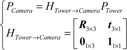
P Tower stands for a point coordinate in the tower frame; P Camera indicates the same point in the camera frame. HTower→Camera extrinsic matrix, describing transformations between the above two frames. R is a rotation matrix, and t is a translation matrix. Here, we can get the coordinate of the camera centre in the tower frame in formula (3).

This coordinate will be treated as one component of system state variables in subsequent computations.
The approach proposed in this paper requires fusing of the data from IMU, GPS and visual pose estimation. Thus, a coordinate transformation is necessary. According to the chain rule of transformation, the overall transformation is divided into five successive frames: (1) world frame; (2) power-tower frame; (3) inertial frame; (4) robot body frame; (5) camera frame.
The transformation matrix between power-tower frame and world frame, which can be pre-calibrated manually as HTower→World when tracking starts, stays constant as in Eq.(4):

P World and P Tower present the same point in the world frame and power-tower frame, respectively.
During the inspection, the flying robot is always changing its pose relative to the tower. The transformations between camera frame and power-tower frame are therefore dynamic, and can be described as in Eq. (5):

where

In formula (6), tTower→Inertial and RInertial→Body have to be calculated in real time, while the other variables can be pre-calibrated.

where γ is roll, β is pitch, α is yaw. R x (−γ),R y (−β),R z (−α) are basic rotation matrices about the x, y and z axes, respectively.
HTower→Camera is obtained as in Eq. (2). Using Eq. (6), RInertial→Body can be easily obtained. Euler angles from visual localization algorithm are finally estimated as in Eq. (8):
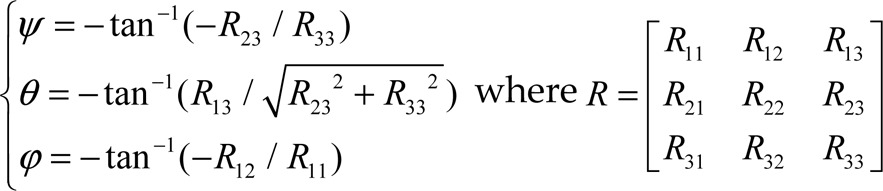
where ψ is roll, θ is pitch, and ϕ is yaw. These three variables partially constitute the flying robot's system state. There may exist different solutions to Eq. (8) when it comes to the implementation of arctangent. In general, raw output of roll pitch and yaw stay with

Purely model-based tracking for pose estimation is executed for successive frames, which also means that the pose estimated in the current frame depends on the one in the last frame. However, due to the complexity of the tower model, when inspecting the tower from a different view, separated edges project closely together in the image. When the tracking algorithm searches the edges, multiple matching points will be found, as shown in Figure 1. If that happens only for few frames, the error stays within an acceptable range. If no pose correction is carried out, however, error will be accumulated, resulting in tracking failure.

Edge ambiguity
In order to solve the problem, fusion of GPS and IMU based on Kalman filters is used to correct the pose for visual tracking.
The Kalman filter method is designed as follows. Say the system state variable X k , as shown in formula (10):

where (x k ,y k ,z k ) T indicates the coordinates of a flying robot in relation to the power-tower frame, (v x,k ,v y,k , v z,k ) T is flying speed, and (ψ x,k ,ψ y,k , z,k ,ω x,k ,ω y,k ,ω z,k ) T is the Euler angles and angular rate of the flying robot.
For a high sampling frequency, it is reasonable to consider that during interval time ΔT, the flying robot is moving at a constant speed. Predictions and updates are given in Eq. (11):

where F k is state transformation model, P k is state covariance matrix, Q k is process noise covariance matrix, R k is measurement covariance matrix, H k is mapping matrix of measurement, and z k = (x k , y k , z k , ψ x,k , ψ y,k , ψ z,k ) T is observation matrix. In the following section, the pose of the flying robot is noted as x k = (x k ,y k ,z k ,ψ x,k ,ψ y,k ,ψ z,k ). T
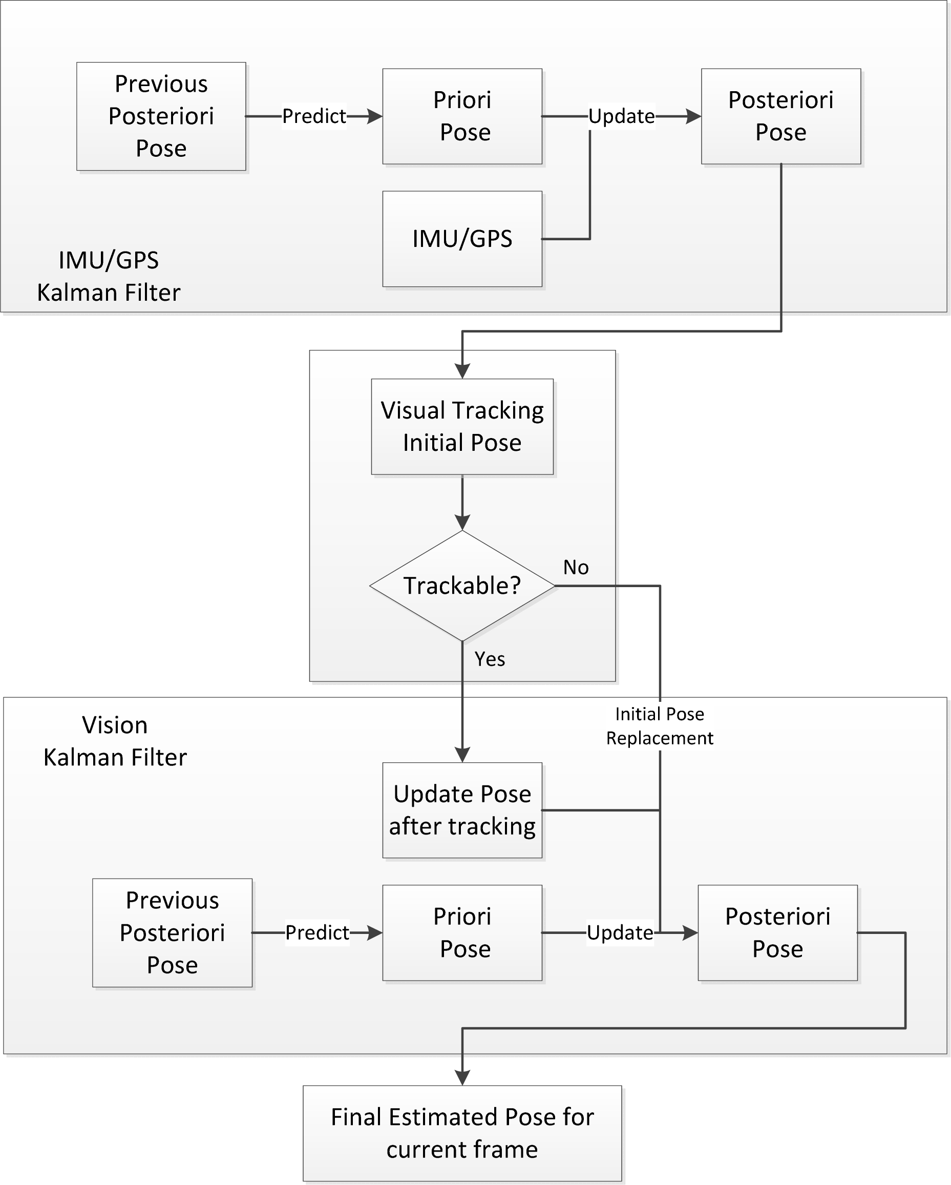
The whole procedure of the proposed method is depicted in Figure 2. The details are as follows:
Recursively estimate a posteriori pose
Gather data from IMU and GPS as observations, marked as z t .
Update pose with observations in (2) and get a posteriori pose
Set pose in (3) as an initial pose for visual tracking. Kalman filter for IMU/GPS ends here.
Track the model one more time to get a pose for the current frame. If it is untrackable, the pose from (4) is directly used as the new pose.
The pose from (5) is regarded as the observation for the vision Kalman filter. After one time update, final pose for current frame is estimated.
Two collaborative Kalman filters are used: (1) Kalman filters can reduce the side effect of random noise; (2) pose correction from IMU/GPS helps to avoid error accumulation for visual tracking; (3) visual-tracking-based pose estimation has higher precision than pure IMU/GPS.
Model-based tracking cannot recover itself once it fails. Thus, when facing with a motion blur, which makes it hard to identify enough feature points, the whole system has to be switched into IMU/GPS-aided localization. As long as the error stays within a specific range, visual tracking can automatically recover when the images become clear. It is worth noting that IMU/GPS-aided localization will increase error to some degree. But when visual tracking is available, error will be narrowed again.
Fusion-based method
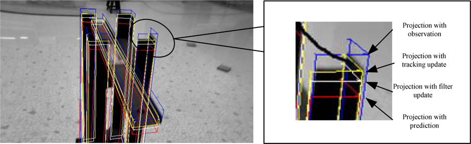
Figure 3 depicts one frame of the tracking procedure. In the IMU/GPS Kalman filter, we get a re-projected edge using predicted pose. Projection with observations means projected edge using purely IMU/GPS data. Through one filter update, a filter-updated pose is calculated. Then, one more tracking is performed to get the visual tracking pose, indicated as a projection with the tracking update. The final edge is located closer to the real-image edge, indicating a higher precision.
Snapshot for stable visual tracking
In order to prove the accuracy and robustness of the proposed method, a comparison between visual localization and fusion-based localization is made.
The whole experiment is carried out as in Figure 2. The experimental device is shown in Figure 4. A flying robot equipped with IMU and a camera with a 640*360 resolution at 30 FPS is used. The tracking target is a mini power-tower model. The operating system is Ubuntu Tinux 12.04. The programs run on a computer with Intel Core i5 2.5GHz and 4G RAM. An IGPS (Indoor Global Positioning System) is employed, simulating a real GPS.
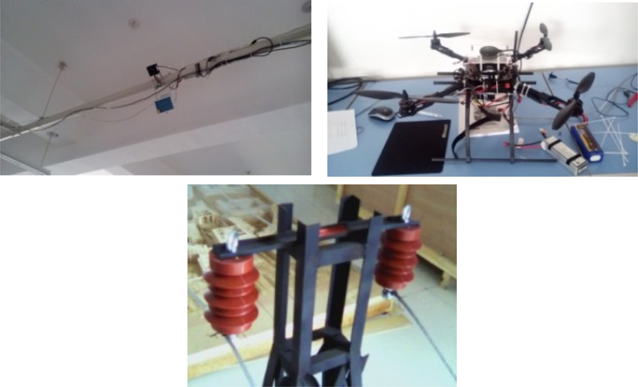
Indoor GPS, quadcopter and mini tower model
As mentioned before, purely visual tracking may fail due to motion blur or edge ambiguity. In order to prove the effectiveness of the proposed method, the experiment focuses on these two specific occasions.
It is key to measure tracking quality so as to determine whether or not switch to IMU/GPS-aided tracking. For 3D-model-based visual-tracking pose estimation, corresponding points sampled along the edges for two successive frames are used to calculate the pose. Therefore, enough feature points must be used for pose estimation. Because of motion blur or camera shaking this number may fall rapidly, which disables visual tracking. Here, points available for pose estimation are defined as Trackable Points (TP), and those not available are defined as UnTrackable Points (UTP). In order to ensure visual-tracking accuracy, a threshold needs to be configured.

When Eq. (12) is satisfied, tracking is considered to be good; otherwise, the system will switch to IMU/GPS-aided localization. In the experiment, the threshold is set to 0.7, which performs well under this circumstance.
Purely model-based tracking suffers from error accumulation out of edge ambiguity, as shown in Figure 5, in which the white frame shows the visual localization result, showing that the error has accumulated hugely, deviating from the real tower target. The red frame stands for fusion-based localization, in which visual pose is corrected by IMU/GPS to avoid error accumulation, demonstrating higher accuracy and robustness.

Error accumulation comparison
As described above, for evaluation of tracking quality, measurement of TP is involved. The amount of TP is somewhat proportional to tracking quality and localization accuracy. Figure 6 depicts the process from stable tracking to error accumulation due to edge ambiguity. TP of fusion-based localization is apparently higher than that of pure visual localization.
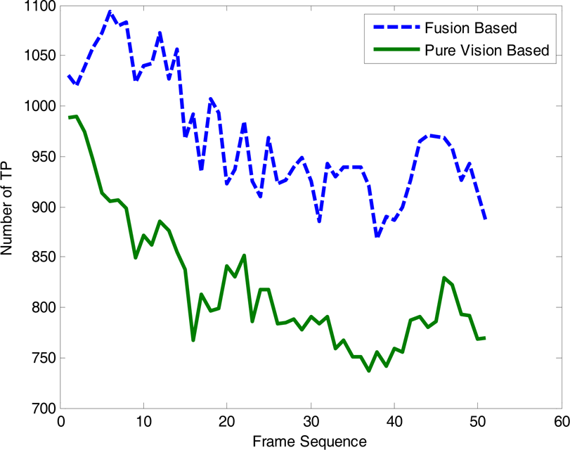
TP comparison
Flying robots may inevitably suffer from sudden camera shaking. The experimental result for camera shaking is shown in Figure 7: the white frame stands for pure visual localization and the red frame for fusion-based localization. As shown, vertical shaking causes edge blurring, and pose difference between two frames is too big, making it unable to find point matches. During shaking TP is shown in Figure 8. TP for fusion-based localization stays high, whereas for pure visual localization, it drops enormously. The proposed method therefore has better performance.
Figure 9 indicates the tracking recovery result after tracking failure due to severe motion blur. The red frame shows the recovery consequence as aided by IMU/GPS; pure visual localization, marked with the white frame, is clearly unable to recover the right pose.

Camera-shaking comparison

TP number comprason

Tracking recovery
In this paper, we propose a new multi-fusion-based localization method for a power-tower-inspection flying robot, in which two collaborative Kalman filters are designed to fuse IMU/GPS and visual information for higher accuracy and robustness. The experimental results show the advantage of being immune to camera shaking and edge ambiguity, meeting the requirements for power-tower inspection.
It needs to be stressed that when the error of IMU/GPS stays within a particular range, the proposed method has relatively high accuracy and stability. However, if the system error for IMU/GPS gets too large, not following a Gaussian distribution, or fluctuates randomly with great magnitude, the initial pose provided by IMU/GPS will not be acceptable, which means visual tracking cannot depend on IMU/GPS anymore. Also, switching to IMU/GPS-aided localization will lose localization precision.
Our future work will have two aims. One is to use an accelerometer in the IMU to partially replace GPS for greater reliability. The other is to fuse the particle filters. With the help of sensors like the IMU, the search space for particle filters will be able to be constrained for better performance.
Footnotes
7.
This work is supported by the Programme for New-Century Excellent Talents in University (Grant No. NCET-11-0634), the National Natural Science Foundation of China (Grant No. 61105083) and the Fundamental Research Funds for the Central Universities (Programme No. 12ZX16).