
Abstract
This paper presents a novel docking system design and the distributed self-assembly control strategy for a Distributed Swarm Flying Robot (DSFR). The DSFR is a swarm robot comprising many identical robot modules that are able to move on the ground, dock with each other and fly coordinately once self-assembled into a robotic structure. A generalized adjacency matrix method is proposed to describe the configurations of robotic structures. Based on the docking system and the adjacency matrix, experiments are performed to demonstrate and verify the self-assembly control strategy.
1. Introduction
Biological imitation is an effective way to design novel robotic systems. Inspired by collective behaviours of social insects or animals, researchers have been studying distributed swarm robots in these years. A basic function of such robots is self-assembly, which is significant for the mimicking of different biological activities [1] and brings about many new compelling advantages.
Self-assembly provides an effective pattern for cooperation among a group of homogeneous robots. By docking with each other and getting physically connected, swarm robots can adjust themselves to unpredictably-varying environments and applications with suitable robotic structures. Thus, swarm robots have more functions than conventional robot platforms and are more flexible when it comes to tasks in unstructured environments such as rescue in collapsed buildings, military spying and planet exploration, etc. [2].
Thus far, most docking systems have been designed for the docking and self-assembly of specific swarm robot platforms and there is a lack of a universally effective solution. Meanwhile, almost all of those platforms are mobile ones [3–8], which have no ability to fly in the air or swim under water. So, there is a wide space to explore in the field of swarm robotics, from docking to self-assembly and from swarm mobile robots to swarm UAVs (Unmanned Aerial Vehicles [9]) or swarm underwater vehicles.
This paper presents the design details of the docking system of a new Distributed Swarm Flying Robot (DSFR) which consists of many identical robotic modules. The modules are able to move on the ground, dock with each other, self-assemble into a robotic structure and then fly coordinately in the air. A distributed self-assembly control strategy is also proposed for the DSFR and its feasibility has been demonstrated by theoretical analysis and experiments. After the modules' self-assembly into a suitable robotic structure on the ground, the whole structure can then take off vertically and fly in the air in a coordinated fashion under distributed control. This paper primarily focuses on addressing the docking system design and the self-assembly control. Work concerning structure-insensitive distributed flying control and multi-robot collaboration will be dealt with in forthcoming papers. The contributions of the present work are highlighted as follows:
Cam-LED-based navigating and positioning solution provides potential docking information and high efficiency during self-assembly; Docking mechanism designed for swarm flying robot is able to withstand burst forces generated among connected robotic modules in the process of flying; Generalized adjacency matrix first put forth in this paper provides an efficient method to describe clearly and directly the adjacent relationships among the modules in a robotic structure; Distributed control strategy based on the robot states and the generalized adjacency matrix guarantees the smoothness and robustness during self-assembly.
The content of this paper is organized as below. Section 2 surveys and analyses the typical swarm robot systems considered as representatives of state-of-art designs. Section 3 gives a depiction of the overall design of the Distributed Swarm Flying Robot (DSFR). In Section 4, the docking system is introduced specifically. Problems with self-assembly control are addressed in Section 5. Then, experiment results are provided in Section 6 to validate the design and the control strategy. Finally, Section 7 summarizes the present work, arriving at the conclusions and pointing to the direction of some future work.
2. Related Work
2.1 Review of Docking Systems
In order to realize a stable physical connection with satisfactory docking performance between robot modules, a series of critical challenges have to be properly met. Of them, guiding, positioning and connecting mechanisms are at the core of innovation.
Firstly, robot modules have to sense their environment and locate themselves with respect to the targets based on their limited perception so that they can navigate to the most favourable position for docking and self-assembly [10–11]. Scholars from different universities and institutes have put forth many perception solutions which are classified and compared in Table 1.
Perception solutions
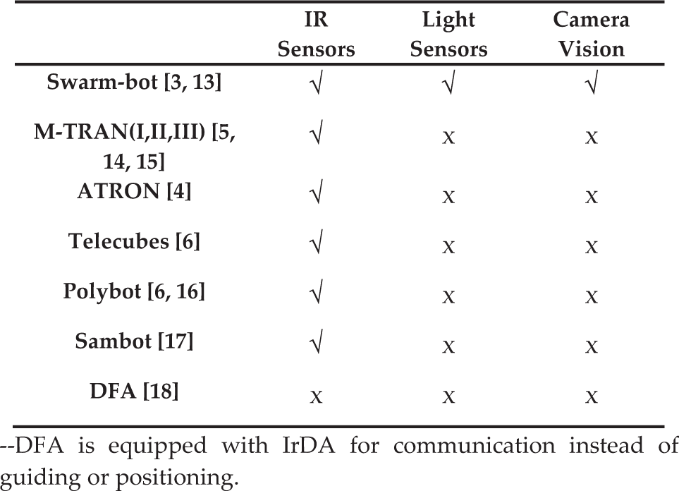
—DFA is equipped with IrDA for communication instead of guiding or positioning.
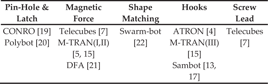
Secondly, the docking mechanisms have to provide a stable connection between robot modules and withstand the burst forces generated by the manoeuvring or locomotion of the robotic structure after self-assembly [12]. The docking mechanisms used by existing swarm robots can be classified into five types as listed in Table 2.
Docking mechanisms
2.2 Self-assembly Control Strategy
Although many so-called self-reconfigurable multi-robot systems exist, most of them have to be pre-attached into a specific structure by human intervention before self-reconfiguration [5, 6, 14]. Few have the ability to self-assemble from discrete individuals into desired patterns without human intervention [3, 17]. The self-assembly control strategies used by these swarm robot systems are addressed as below.
Swarm-bot [3, 23, 24]: during autonomous self-assembly, a group of s-bots locate, approach and connect with the target object or s-bot. The process of self-assembly is governed by the local attraction (red colour ring) and repulsion (blue colour ring) among s-bots. The main part of its control module for self-assembly is a reactive neural network which maps sensory inputs to motor commands.
Sambot[17]: the docking and self-assembly are behaviour-based and aided by limited sensory inputs and local communications. In the process, the active docking sambot (Active_SA) searches for, navigates to and docks with a passive docking sambot (Target_SA). Robots autonomously switch from one behaviour to another during self-assembly. After an Active_SA successfully docks with a target robot, it becomes a passive docking robot.
M-TRAN [25]: strictly speaking, M-TRAN is a self-reconfigurable robot rather than a self-assembly one. For M-TRAN, self-assembly means docking between two different robotic structures instead of that among discrete individual robot modules. The strategy requires an onboard camera installed on a pre-attached periodic structure, some optical transmitters mounted on M-TRAN modules and a docking port configuration to absorb alignment errors. The docking process is divided into two phases. In phase I the system repeats a cycle of image acquisition, relative position estimation and one-step locomotion towards the docking area. In phase II positioning and docking are completed by the closing motion of the docking port.
DFA [18]: because the DFA modules do not have relevant sensors for positioning, the self-assembly is a random process, which cannot be guided or navigated. Only when two modules get near enough stochastically will they be pulled together by permanent magnets. So, self-assembly of DFA is an unpredictable process to a certain degree and people do not know the final structure before self-assembly completes.
3. Overall Design of a Distributed Swarm Flying Robot
DSFR combines together the features of multi-robot cooperation and self-assembly into a swarm flying robot system, which can not only move on the ground, but also fly in the air. The challenges come from many aspects such as mechanical design, sensor configuration, inter-module communication, signal processing, power consumption, etc.
Basically speaking, DSFR should have the following key features concerning mobility, docking and flying:
DSFR modules should have agile mobility on the ground. DSFR modules should have sufficient, but minimum sensibility. Robot modules should be able to connect and disconnect with one another. Once self-assembled, the whole robotic structure should have the ability to take off and fly in the air.
As shown in Fig.1, the shape of a DSFR module resembles a hexagon of EPP material. On its chassis, three omni-wheels driven by DC motors are installed to allow the robot module agile mobility on the 2D plane. The robot module can move to the docking position flexibly and quickly. Each module has six lateral surfaces for connection, including one active connection surface with docking hooks and five passive connection surfaces with docking grooves. Three RGB LEDs and two infrared proximity transceivers are allocated on each connection surface. Every active connection surface still has an additional CMOS camera. To obtain better thrust force, a two-blade propeller is mounted on the brushless DC motor which is housed in a duct. For more specific attributes of DSFR, please refer to Table 3.
Basic attributes of a DSFR module


A graphic 3D model for a DSFR module: 1 – Omni-wheel; 2 – Active Connection Surface; 3 – Passive Connection Surface; 4 – CMOS Camera; 5 – Propeller; 6 – EPP Profile
The electrical design of a DSFR robot module is given in Fig. 2. The infrared transceivers, LEDs, motors and omni-wheels are divided into three groups which are controlled by three MEGA8 driver boards, respectively. The brushless DC motor is driven by a custom ESC (electrical speed controller) with a MEGA8 single-chip processor. All the four MEGA8 processors communicate with the main STM32 processor through the I2C bus. Multi-robot communication has two options. Before self-assembly, robot modules can communicate with each other through a zig-bee wireless network. Once physically connected, they can communicate through the CAN bus. An IMU is incorporated into the system, providing attitude and heading reference data to the robot module through an UART port while flying. A MEAG128 PPM Encoder is linked into the STM32 main processor through an ICP channel, which encodes the RC signal. So, the robot can be operated manually through a joystick RC controller if needed.

Schematic diagram of the electrical system
4. Docking System Design
A docking system is designed based on the camera-LED combination vision feedback and hook-grove match connection mechanism. The details of the design are given in the following two subsections.
4.1 Guiding and positioning sensor configuration
As shown in Fig. 3, the DSFR module has 30 sensors (i.e., 18 LED sensors and 12 infrared ones) to provide sufficient information on guiding and positioning.

Sensor configuration for guiding and positioning
Two LEDs with an interval of 40mm are fixed on the upper-side of each connection surface and all the six connection surfaces have 12 LEDs. In addition, the other six LEDs are fixed on the inner cylindrical surface of the module and each one is 30mm behind the corresponding two connection surface LEDs and high enough to have a suitable sensing range. A CMOS camera is installed on the active connection surface, oriented to the outside of the module to acquire a whole image of the surroundings. In the front view, the three LEDs form a regular triangle whose edge length is 40mm and the camera is at the centre of the triangle. In addition, two infrared proximity sensors with an interval of 140mm are equipped on each connection surface, which helps to calculate the relative position when two DSFR modules get so near that the LEDs are out of sight of the camera. They would also be helpful for obstacle avoidance.
4.2 Docking and connecting mechanism
A mechanical hook-groove match is designed to connect adjacent DSFR modules. As shown in Fig. 4, two docking hooks are equipped on the active connection surface. A worm gear is adopted to drive the hooks because it can transmit larger force than most other mechanisms. The two hooks are installed symmetrically with respect to the worm gear. So, when the driving motor rotates in different directions the hooks can also open or close symmetrically. On the other hand, there are two docking grooves on every connection surface which can match with docking hooks complementarily once two modules are connected.

Docking and connecting mechanism: driving principle with worm gear (left), optimized shape of docking hook (right)
Optimization design has been done for the shape of the docking hook. In order to avoid slight sliding between two connected modules, a locking groove is designed at the root of the hook. Moreover, as is shown in Fig. 4, force generated at the contact area goes through the hook axis. Therefore, no additional torque is generated on the hook.
In order to enhance the docking performance and lower down the accuracy requirement for alignment, the docking mechanism should absorb alignment errors as much as possible. Figure 5(a) shows the perfect alignment of docking. However, in most cases, there may be angle errors and/or displacement errors as shown in Fig. 5(b), (c) and (d).

Error tolerance: a. perfect alignment case; b. angular error tolerance; c. horizontal error tolerance; d. vertical error tolerance
5. Self-assembly Control
Before the self-assembly starts, a robot module is randomly chosen as the seed, which acts as the first module of the robotic structure and will not move until the whole self-assembly process finishes. Then, all the other modules begin wandering to find the structure. Once a wandering module finds the structure, it switches into the navigation process to locate and align itself to the target connection surface. When the module gets near enough and aligned to the passive host module, it actively docks with the structure. If it succeeds, the active robot module becomes part of the structure, if it fails, it goes back to wandering again. The robot modules repeat the states of wandering, navigating and docking until they are assembled into the target robotic structure. When all modules are in the connected state, the self-assembly process ends.
DSFR is a swarm robot system including a large number of robot modules. Certainly, the number may change according to different applications or tasks. To reduce the multi-robot communication consumption and enhance system scalability, a decentralized and homogenous control strategy is applied to all DSFR modules.
5.1 Guiding and positioning strategy
5.1.1 Guiding
Colours of LEDs are used to provide guiding signals. In the process of self-assembly, all the modules show their states with the LED-colour settings. The undocked modules set their top LEDs blue, while the docked ones set their top LEDs red. The undocked modules with blue bottom LEDs are in the wandering state and those with green bottom LEDs are in the navigating state. The docked robots use their bottom LEDs to show where the target connecting surface is relatively located. Most importantly, when all the LEDs on a target connecting surface are set red, it gives a signal of “dock here” to the undocked modules. With the guiding information provided by the LEDs, the robot modules are able to find the target connecting surface efficiently. For the details of the LED settings, please refer to Fig. 6.

Guiding Information (from left to right): move right, move left, dock here, wandering and navigating. The first three are used to guide undocked robot modules and the last two are used to show the states of robot modules
5.1.2 Positioning
Before docking begins, the active docking module has to align its active connection surface to the target connection surface with high accuracy. The alignment is achieved through the principle of camera-LED combination vision feedback. Figure 7 gives a top view of the schematic diagram of this principle.

Positioning and aligning principle
As shown in Fig.7, α is a structural parameter determined by LED positions.

f is the distance from the camera lens to the CMOS sensor panel which is also a structural parameter determined by the camera module. 


According to these equations, once the ratio of 
where

5.2 Self-assembly strategy
The self-assembly strategy is based on the robot states mentioned above in Section 5 and the configuration description matrix given in this section. During the process of self-assembly, all the robot modules are state machines, as shown in Fig. 8. There are only four states: wandering, navigating, docking and docked. The configuration description matrix is a special kind of two-dimensional matrix whose elements are a series of ordered real numbers indicating the surface numbers of two connected modules. We call it a generalized adjacency matrix, because it can express the adjacency relationships between the modules of a robotic structure clearly and directly. Figure 9 gives an example describing a robotic structure composed of three modules. The generalized adjacency matrix is a kind of symmetric matrix whose main diagonal elements are all real number couples such as (0, 0). Thus, only the upper or lower triangular elements need to be considered before the whole structure is established. In the process of self-assembly, the differences between the current structure and the target one can be identified conveniently by comparing the current and target adjacency matrices.

The state transition diagram
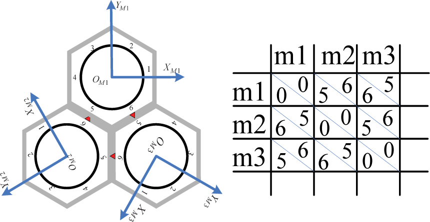
An example robotic structure described by generalized adjacency matrix
The algorithms of the self-assembly strategy are described in pseudo-code language as below for the robots in different states, respectively.
Refer to the appendix of the details of Wander(), Navigate() and Dock().
6. Experiment Result Demonstration and Validation
Self-assembly experiments of three DSFR robot modules have been carried out to demonstrate and testify the docking system and self-assembly control algorithms.
6.1 Experiment
The experiment is carried out on an indoor plain floor with no boundary. At the beginning, only the seed robot is started and it does not move during the self-assembly process. Then, the other two robot modules are put onto the floor at random positions and they begin to wander one after another. Finally, the robot modules accomplish self-assembly autonomously.
6.2 Results
The self-assembly experiment has been repeated many times. Figure10 (a) outlines a simple self-assembly process along time, during which all the robot modules quickly find their target connecting surfaces without spending much time in navigating. However, that is not the common case. Figure 10 (b) shows a more typical self-assembly process, during which the robot modules consume more time in wandering and navigating before they finally dock with the targets. Fortunately, the typical self-assembly process only takes about one more minute, which is also satisfactory.

Self-assembly experiments
6.3 Analysis
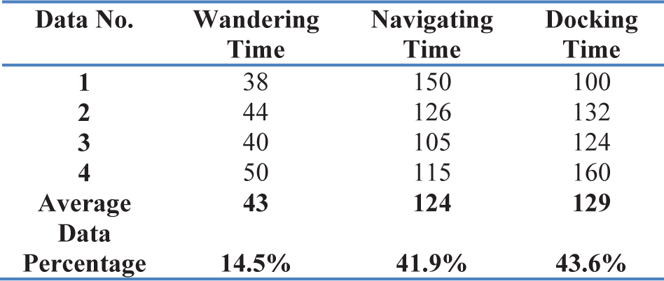
Based on a large amount of experimental data during self-assembly, it is found that wandering takes up 14.5%, navigating 41.9% and docking 43.6% of the whole time consumption.
Time consumption analysis of self-assembly
7. Conclusions and Future Work
A novel Distributed Swarm Flying Robot (DSFR) system is developed and the design of its docking system, as well as the self-assembly control, is proposed. The following contributions make the present work unique.
The cam-LED-based solution for navigating and positioning provides potential docking information and yields high self-assembly efficiency.
The docking mechanism designed for the swarm flying robots is able to withstand the burst force generated between connected robot modules during flying.
The generalized adjacency matrix provides an efficient method for the description of robotic configuration after self-assembly. It is first put forth in this paper and it can show the adjacency relationships between robot modules clearly and directly.
The distributed control strategy and the generalized adjacency matrix can guarantee the smoothness and robustness of the self-assembly process.
The DSFR is a system having the features of swarm robots, self-assembly robots and flying vehicles. This makes it a complicated system rich in behaviours, cooperation patterns and dynamics, and leaves much room for further study. Much future research can be done to further improve the design of DSFR. For example, an agile manipulator may be used to make the docking mechanism better, so that the robot module can have additional ability to grasp and transport other objects. In addition, flying test may be carried out to yield the necessary data for the improvement of the distributed flight control.
Footnotes
8. Acknowledgements
This work was supported by the National High Technology Research and Development Program of China (“863” Program) (2012AA041402), National Natural Science Foundation of China (grant no. 61175079 and no. 51105012), Fundamental Research Funds for the Central Universities (grant no. YWF-11-02-215).