
Abstract
This paper introduces a novel robot designed to exhibit two distinct modes of mobility: rotational aerial flight and terrestrial locomotion. This versatile robot comprises a sturdy external frame, two motors, and a single wing embodying its fuselage. The robust frame not only facilitates mobility but also makes the robot collision-tolerant in both modes, enhancing its resilience in challenging environments. The robot is capable of vertical takeoff and landing in mono-wing flight mode, with the unique ability to fly in both clockwise and counterclockwise directions, setting it apart from traditional mono-wings. While relying on just two actuators, the robot seamlessly transitions to ground locomotion mode, utilizing its frame to facilitate rolling motion on the ground. The unique design ensures that the robot avoids any unrecoverable states, making it exceptionally robust and reliable in diverse operational scenarios. The robot demonstrates the capability to perform controlled ascents and descents on inclined surfaces with gradients of up to 15°. The integration of ground rolling mode significantly enhances operational efficiency. The paper provides a comprehensive overview of the robot’s design, dynamic model and functionality, along with experimental results for waypoint tracking in both aerial flight and terrestrial locomotion, its turning ability on various surfaces, the bi-directional transition, power consumption, and an example application outdoors. The combination of minimal actuators enabling different modes of mobility and robustness against unrecoverable states highlights the distinct capabilities and reliability of this platform.
Keywords
1. Introduction
The field of robotics has witnessed remarkable advancements in recent years, particularly in the domain of aerial robots (Kumar and Michael, 2012). Aerial robots have proven invaluable for autonomous inspection and surveillance tasks, offering the ability to navigate over obstacles and inaccessible terrains while providing a comprehensive bird’s-eye view of the environment (Floreano and Wood, 2015). However, the high energy consumption of these aerial vehicles results in limited flight time and mission range, posing significant challenges and hindering their widespread application in certain scenarios (Tennekes, 2009; Bauersfeld and Scaramuzza, 2022).
The need for efficient power utilization in multi-copters, and their limited endurance and range, has motivated the exploration of hybrid design of aerial vehicles. For flight endurance, hybrid aerial vehicles with the ability to perch (Graule et al., 2016; Nguyen et al., 2019) or lean (Hsiao and Chirarattananon, 2019) on nearby surfaces have shown significant potential for surveillance with lower power consumption. Self-rotating aerial vehicles (Driessens and Pounds, 2015; Chen et al., 2023; Bernardes et al., 2023; Win et al., 2022; Bai et al., 2022) have shown superior hovering efficiency compared to conventional multi-rotor platforms. Moreover, these platforms tend to utilize a smaller number of actuators, thereby increasing the overall efficiency of the platform (Bai et al., 2022; Win et al., 2021). A single-wing variant of this platform, known as a mono-wing, has been utilized for short-range urban surveillance (Jameson et al., 2012) and LiDAR inertial odometry (Tan et al., 2021b). The platform has also been utilized on a robot in two different flight modes in Bhardwaj et al. (2022) and as a modular version in Cai et al. (2023).
Researchers have developed hybrid robots designed for surveillance and long-distance travel. These robots can fly over obstacles and save energy by moving on the ground. There are different ways in which researchers have achieved the ground locomotion phase. Walking/crawling motion provides the ability to transverse while dealing with rough terrains, however, it comes at a cost of sophisticated linkages or additional actuators (Pratt and Leang, 2016; Ratsamee et al., 2016; Mulgaonkar et al., 2016; Kim et al., 2021; Chukewad et al., 2021). Researchers in Zhang et al. (2022), Kalantari and Spenko (2014), Dudley et al. (2015), Yang et al. (2022), Qin et al. (2020), and Pan et al. (2023) utilize lightweight cylindrical cages, spherical shells, or light passive wheels for locomotion on the ground. These robots utilize the horizontal component of their thrust for actuation, requiring no additional actuators on the ground. However, since the attitude is being controlled by the same flight controller, these drones are still consuming high energy even in the ground locomotion mode, therefore, making them less energy efficient on the ground. On the other hand, researchers in Tan et al. (2021a), Choi et al. (2021), and David and Zarrouk (2021) employ additional actuators for different modes of flight, which accounts for extra weight to be carried in flight mode, making these designs relatively heavy. Similarly, researchers in Wang et al. (2019) developed a transformable frame robot, incorporating extra actuators for transformation. Adopting a weight-saving approach and leveraging the aerial mode actuators to supply power in ground mode, researchers in Jia et al. (2023) developed a passively reconfigurable frame for ground locomotion, employing a quadcopter design for aerial flight. Likewise, researchers in Zheng et al. (2023) utilized a single servo in conjunction with quadcopter motors to enable ground locomotion.
This research is motivated by the need for versatile robots that can operate effectively in diverse environments while using limited energy resources. The research aims to expand the existing knowledge of hybrid robots that operate in both air and land by harnessing the advantages of an under-actuated flight platform (such as a mono-wing) and terrestrial robots’ features. By integrating these two modes of movement, with a seamless transition capability between them, our platform seeks to enhance the capabilities and applications of such robots beyond what each mode can achieve independently.
We introduce our novel robot called Aerial and Terrestrial mode Operating Mono-wing (ATOM). Owing to its design, ATOM can fly in the rotational mono-wing mode (Figure 1(A)) in both clockwise and counterclockwise directions, which is unlike a traditional mono-wing with a fixed direction of flight. ATOM utilizes two counter-rotating motors mounted on either side of the wing to balance the torque and precession required for the robot’s aerial mode (A-mode) flight. This design helps achieve flight in different rotation directions and allows control over the rotational speed to some extent. In previous research, we highlighted the benefits of rotational velocity control on a mono-wing (Bhardwaj et al. 2023). Moreover, ATOM has the capability to do ground locomotion in its Terrestrial mode (T-mode) by rolling on the floor from one place to another using its frame (Figure 1(B)). ATOM can achieve an effortless transition between the two modes of transportation, as and when required. An external frame offers the additional benefit of enhancing collision resistance for the A-mode. Our design for a hybrid aerial and terrestrial robot stands out from others in the literature because it only uses two actuators for both modes. The potential applications of such a robot include search and rescue missions, surveillance operations, and environmental monitoring, and are further discussed in discussion section. (A) ATOM during an aerial mode flight, rotating in counterclockwise direction. (B) ATOM traverses over land by rolling on its frame. The image depicts ATOM ascending a 5° inclined surface.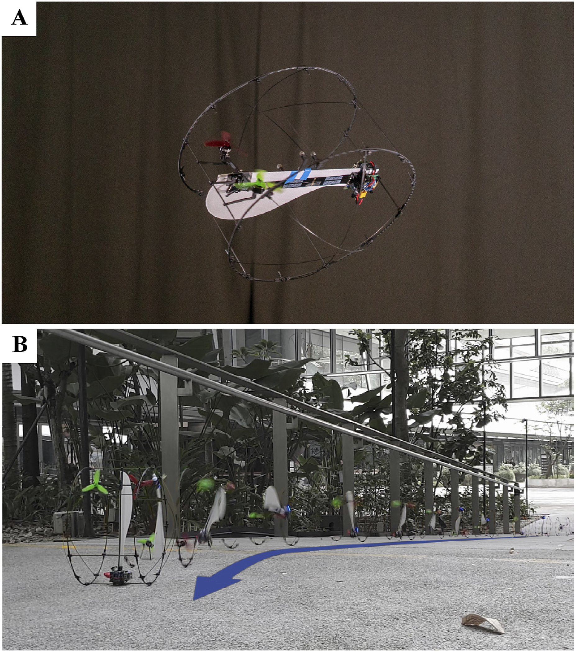
Recent research done in Suhadi et al. (2023) introduced a mono-wing design capable of ground locomotion. However, the design experiences a significant drag issue due to friction, limiting its mobility to smooth surfaces with low friction coefficients and resulting in a reduction of ground velocity. On the contrary, ATOM’s design incorporates a wheeled frame, enabling it to roll across the ground with reduced friction impact. While ATOM does encounter high friction during turns, we effectively address this challenge by implementing a reverse thrust mechanism on the motors. Additionally, ATOM’s design also allows it to fly in both directions of rotation, unlike Suhadi et al. (2023), which is restricted by its design to fly in only single direction of rotation. In contrast to other rolling frame hybrid robots (such as Jia et al. (2023) and Zheng et al. (2023)), ATOM stands out due to its distinctive design, featuring only two actuators. One limitation observed in many hybrid drones documented in literature is their inability to function if they land upside down, necessitating manual intervention for recovery. ATOM’s design overcomes this challenge through a unique frame design and strategically positioned center of gravity. These features ensure that ATOM avoids any unrecoverable states, maintaining operational capability regardless of its orientation upon landing.
The novelty of this research can be summarized as follows: • Dual-mode mobility with minimal actuators: Using only two actuators, the robot achieves both aerial and ground locomotion, as well as transitions between these modes. • Design ensuring recoverability: The robot’s design avoids any non-recoverable states on the ground by enabling bidirectional take-off and flight. • Simplified structure with robustness: The minimal design of the robot combined with the external frame ensures three passive equilibrium states on ground, makes the robot collision-tolerant in both modes, and provides structural integrity.
In the following section, the design principles of ATOM are elaborated along with a description of the different parts and components onboard the prototype developed. Subsequently, the dynamic modeling and flight control of the platform are discussed. Thereafter, the results are then presented, followed by a conclusion in the final section.
2. Prototype design
This section describes the design and manufacturing of the robot’s wing, frame, and other onboard electronic components. The weight breakdown of the ATOM prototype is shown in Figure 2. It should be noted that the battery and the frame structure form about 55% of the weight of the prototype. Weight breakdown of the ATOM prototype. The battery and the frame contribute nearly one-third and one-fourth of the overall weight, respectively. The miscellaneous (misc.) includes the weight contribution of screws, nuts, and PCB connecting the motors to the ESCs.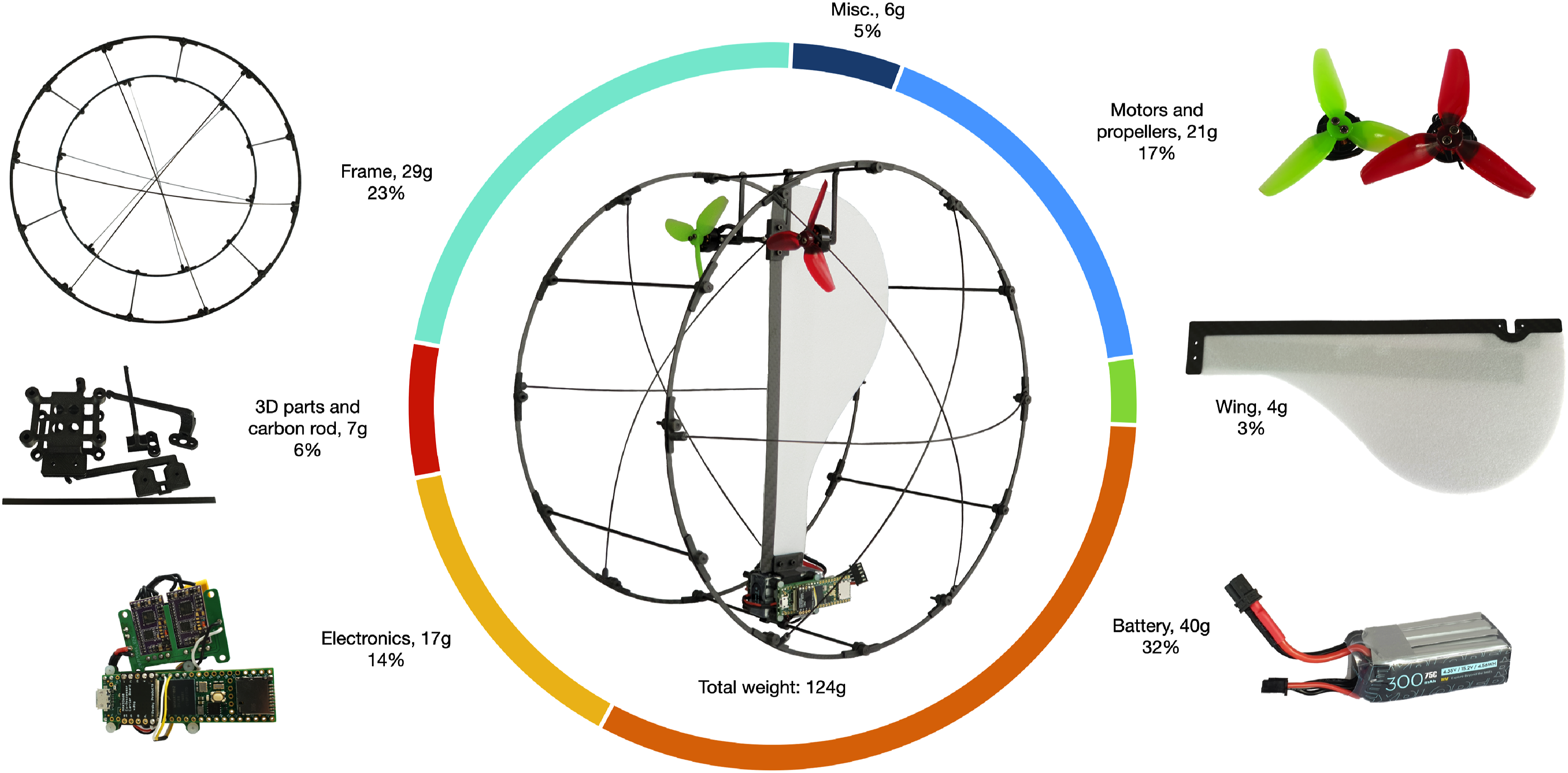
2.1. Wing design
The wing’s design mimics the Samara seed, featuring a tapered shape with a narrower root and a wider tip, optimizing aerodynamic force generation over a larger wing area. To maintain the robot’s lightweight profile, a 1.5 mm thick foam is chosen as the primary wing material. To enhance structural integrity, the leading edge of the wing is reinforced with a 0.5 mm thick carbon sheet extending from the root to the tip. 3D-printed parts firmly connect the root and tip of the wing to the frame structure.
2.2. Frame design
The frame enables the robot to achieve locomotion in T-mode. The circular wheel-like design enhances the robot’s capability to smoothly roll and move. Although the frame serves as a protective cage for the robot during A-mode flight, it remains unused in this flight mode. Therefore, it represents an excess weight carried by the robot in A-mode. Therefore, the frame was carefully designed to keep as little weight as possible, while maintaining the robot’s structural strength in T-mode. Thin carbon fiber rings (3 mm wide, 1 mm thick) were utilized as the main structural rings, which were joined by 2 mm diameter hollow carbon rods. Besides the main circular rings, which are utilized for their structural strength, the frame consists of reinforcement rods that form two segments at an angle (ζ0) on the upper and lower part of the robot. The placement of these reinforcement rods is done evenly with respect to the geometric center (GC) of the rings. Therefore, the center of gravity (CG) located toward the root of the mono-wing, sits in-between a specific sector of the circular ring. This ensures a passively stable equilibrium position for the resting robot in A-mode (on both sides). The CG of the mono-wing is required to be toward the root of the robot to obtain an efficient flight. Since the CG is located at a lower height compared to the GC, the robot rests in the second passively stable equilibrium position in T-mode. The three static equilibrium positions of ATOM are demonstrated in Supporting video S1. The root of the mono-wing and the robot both refer to the battery side, which is the heavier side of the body (depicted with a blue cuboid in Figure 3(A)). (A) Dynamic model depicting the forces and torques produced by actuators in A-mode. Motor 1 (M1, mounted with green propeller) and Motor 2 (M2, mounted with red propeller) produce thrusts T1 and T2, respectively. The battery is depicted with a blue cuboid. (B) Aerodynamic forces acting on a single wing element. (C) Dimensional parameters depicting the position of the center of gravity diameter-wise (l1 from the battery side, l2 from the motor side) and height-wise (h), and geometric angle ζ0 described further in the section describing transition from one mode to another. (D) Robot depicting the rolling forward motion in the terrestrial locomotion mode. (E) Side view of ATOM, depicting the rolling dynamics, and definition of the roll angle γ, the geometric center, and the contact point reference frames. (F) Top view of ATOM, depicting the turning dynamics and definition of the turn angle α.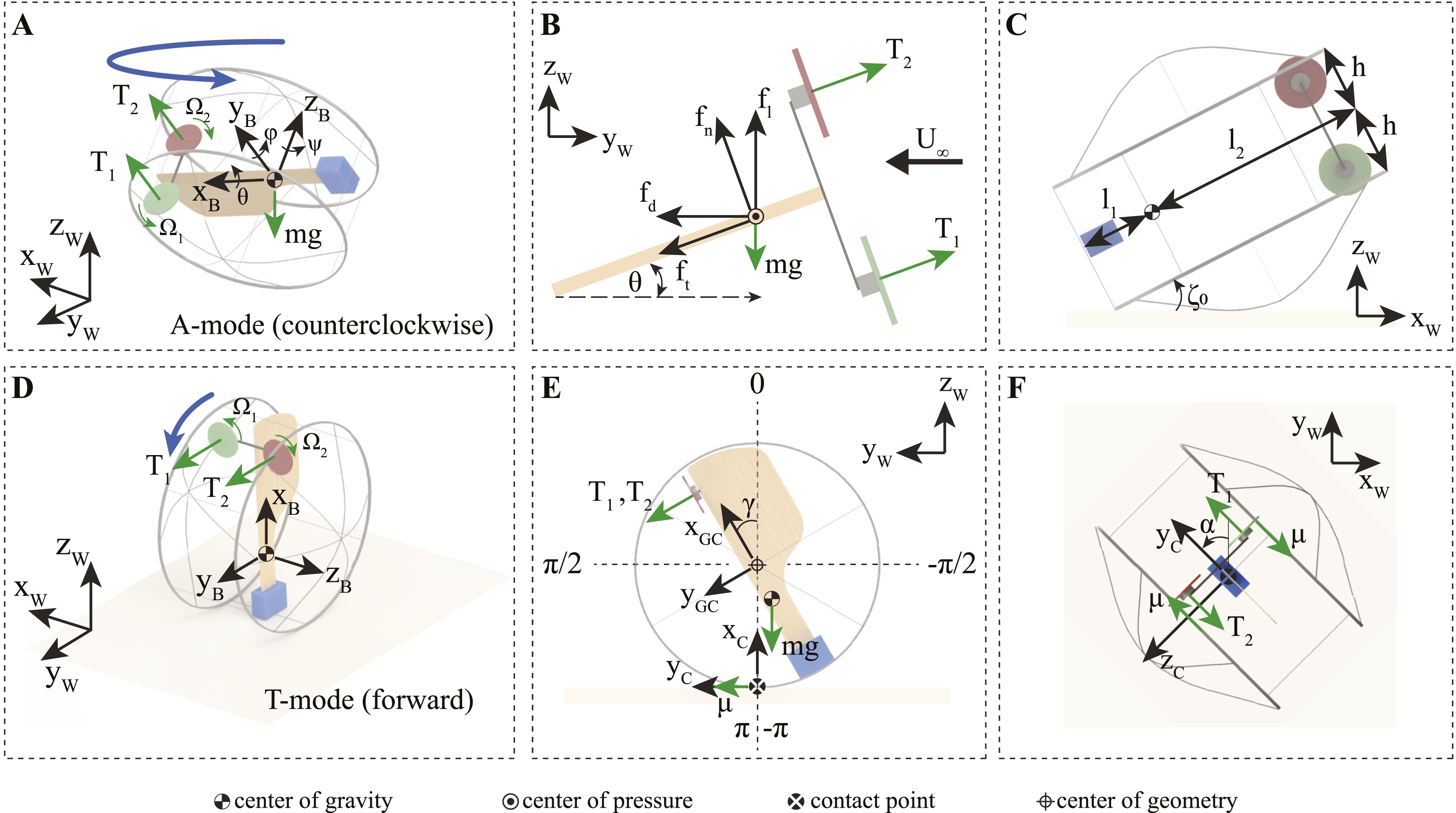
The angle of curvature of the reinforcement rings was chosen carefully to provide structural stiffness to the main ring. Equal distribution of these rods along the circumference on both sides provides the desired rigidity to the frame, enabling it to bear the load of the components. Besides the structural strength, this curvature also plays a crucial role in the transition of the robot from one mode to another. A less angle value requires more effort by the motors in transition from A-mode to T-mode, whereas, a high angle value provides an unsteady performance for a transition from T-mode to A-mode. This has been explained further in the dynamics and control section under the transition part.
2.3. Electronics
The design of this robot is distinct compared to other monocopters developed in the literature due to the unique vertical positioning of the two motors. Both motors are placed at the leading edge of the wing, connected by a rigid carbon fiber rod. The robot utilizes BETAFPV 1404 4500 KV motors in conjunction with BETAFPV HQ3030 3-blade propellers. The reason for using two opposite rotation direction motors for this platform is to utilize differential thrust in T-mode for directional control and to allow the robot to fly in both directions in A-mode. The electronic speed controllers (ESCs) are reprogrammed to allow reverse thrusting on motors, enabling the robot to roll forward as well as backward in T-mode. The robot employs EMAX Bullet 30A as the ESCs onboard, which are mounted on a PCB positioned next to the microcontroller (Figure 2, electronics). Two thin flexible Printed Circuit Boards (PCBs) connect the ESCs to the motors. An Inertial Measurement Unit (IMU) provides the magnetic heading direction and rotational rates of the robot. The robot utilizes a Teensy 4.1 microcontroller as the flight controller with Pesky USFSMAX as the IMU. The battery utilized onboard is Flywoo 4S 300 mAh.
2.4. Design limitations
Due to the lightweight design, the robot is unable to accommodate high-impulse thrust changes required for abrupt directional changes in T-mode. This means that it would be difficult to roll forward and execute sharp turns, without the risk of tumbling over. To overcome this limitation, the robot stops before turning left or right, makes the desired turn, and then continues forward again. However, this constraint does not apply to large-radius turns, which the robot can execute smoothly while moving forward, as explained in the following section.
Another limitation of this design is the inability of the robot to stop instantly at any location. Because the robot’s CG is not precisely at its center, it is important to note that once the robot comes to a stop, its inherent tendency is to either roll forward or backward in order to re-establish its passive stable equilibrium position. It is possible to maintain a desired attitude by using thrust from the motors; however, consistently working against gravity would be counterproductive.
3. Dynamic modeling and control
This section details the modeling of the robot in different configurations, namely, A-mode, T-mode, transition from A-mode to T-mode, and vice versa.
3.1. Aerial flight mode
One of the default resting states of the robot is lying flat on either of its sides, which is the default take-off state for A-mode (Figure 3(A)). Once the motor commands are applied, the robot starts to spin as depicted and takes off.
The revolving wing profile of ATOM experiences significant aerodynamic forces. Using the Blade Element Theory (BET) (Leishman, 2006), the lift(f
l
) and drag(f
d
) forces generated by a single wing element of width dr at a radial distance r can be modeled by


As depicted in Figure 3, two motors with propellers are rigidly attached to the wing’s leading edge, and the propellers’ force is parallel to the y-axis of the body frame. The propeller-generated force and reaction torque can be represented as T
i
and

Due to the spinning motion of the motors and propellers along with the body frame, a precession torque (

Let
Considering
Therefore, the attitude dynamics of the robot can be written using Euler’s equation as

In aerial mode, the robot’s attitude is controlled by a cyclic controller, akin to the swash plate mechanism found on helicopters. In contrast to the swash plate mechanism, the motors generate periodic thrust to control roll and pitch. Cyclic control for rotating aerial vehicles has been well established in the literature, and in this research work, square cyclic control strategy from Bhardwaj et al. (2021) has been adapted.
The amplitude of the cyclic command, denoted as T
amp
, corresponds to the amplitude of the roll and pitch inputs, ϕ
c
and θ
c
, respectively. T
amp
and the direction control variable, ψ
c
, for pitch and roll inputs, are determined by
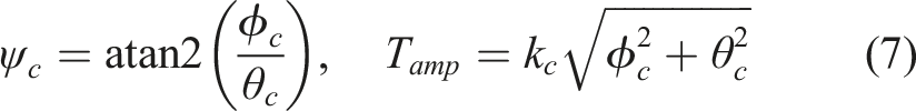
In single-motor actuated monocopter, T cyc is provided to the motor for flight, as described in Bhardwaj et al. (2023). ATOM has a unique design that features two motors mounted at equal distances on each side of the wing. Due to the offset of the motors from the wing, actuating only a single motor will create an excess of torque. Therefore, ATOM would not be able to fly using just a single motor. The robot utilizes the second motor onboard to balance the torque, enabling it to fly. To maintain a positive pitch for the wing, the bottom-mounted motor is provided T cyc , whereas the top-mounted motor is used for the balance of torque.
During manual flight, T
o
is directly mapped to the throttle value from a radio controller. Similarly, the roll and pitch input commands necessary for computing T
amp
are directly associated with the roll and pitch stick, respectively, on radio controller. In a closed loop position control, the x and y axis correspond to the roll and pitch of the robot. A sliding mode control is used to control the position, where the sliding surface is defined as


3.2. Terrestrial locomotion mode
To describe the motion in T-mode, we introduce two new reference frames. The first reference frame {x GC , y GC , z GC } is located at the geometric center of the robot, and the second reference frame {x C , y C , z C } is located at the contact point between the ground and the robot (Figure 3(E)).
3.2.1. Rolling dynamics
The rolling motion of the robot is defined as the rotational motion of the geometric center reference frame. Considering no slipping, the motion can be defined using angle γ, which is the angle between the x
GC
and x
C
axis (Figure 3(E)). The rotational dynamics with respect to the ground contact reference frame can be described as


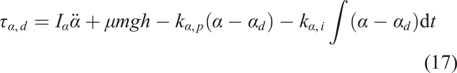
To control the rolling motion, a PD controller is implemented to calculate the desired torque τγ,d, as
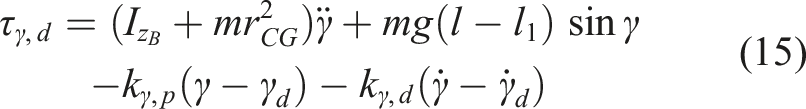
3.2.2. Turning dynamics
A heading control for the robot is implemented to change the direction in T-mode. To ensure the maximum value of effective thrust is utilized solely for turning, the robot only executes the turn when γ ≈ 0. To ensure this, the aforementioned roll control mechanism is employed. To turn left/right, ATOM utilizes the differential thrust from the motors to produce the torque required for a controlled turn in the desired direction. Figure 3(F) depicts the dynamics associated with the turning of the robot. The heading angle is defined as α, which is the angle between the y
W
and y
C
. The turning dynamics can therefore be described as

To control the turning motion, a PI controller is implemented to calculate the desired torque τα,d, as
3.2.3. Rolling and turning force and torque generation
To start rolling in the forward direction, the robot must apply a minimum amount of torque (τmin) that can overcome the rotational inertia of the system and gravity, to produce a complete spin. Using the principles of rotational motion and equilibrium, this torque can be evaluated as
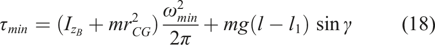
Subsequently, both propellers are activated in the designated zone (according to equation (19)) to provide the robot with the rolling torque required to overcome friction and other induced forces that can slow the system. Once the propellers cross the threshold mark, they are deactivated as the robot rolls forward due to inertia and gravity. That is, for forward motion,
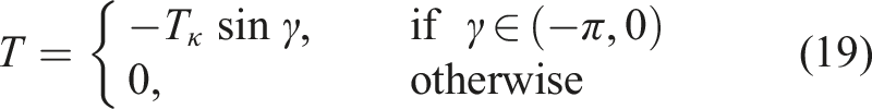
The turning dynamics can be effectively employed to execute left or right turns when the robot is not in a rolling motion. However, it is worth pointing out that ATOM also possesses the capability to change direction with a larger turn radius while simultaneously rolling forward, without stopping. This turn-while-rolling maneuver is achieved by providing a low-magnitude impulse thrust to change the direction when the robot is in the desired orientation. Mathematically, equation (19) is modified as follows:
3.3. Transition from one mode to another
The transition from one mode to another involves moving from one passively stable equilibrium position to the other. Once the transition is complete, the robot comes to rest on its own, however, controllers are utilized to stabilize the oscillations after the transition is complete. For both transitions, it is assumed that there is no slip condition between the ground and the robot at the contact surface.
3.3.1. Transition from aerial to terrestrial mode
The unique design of the robot is exploited to perform the transition from A-mode to T-mode. Figure 4(A) depicts the process of transition from A-mode (clockwise rotation) to T-mode in three stages. Due to its highly underactuated design, the robot can only generate a direct torque about x
B
and z
B
axes. A torque around z
B
merely induces spinning motion of the robot. However, by strategically generating controlled torque around x
B
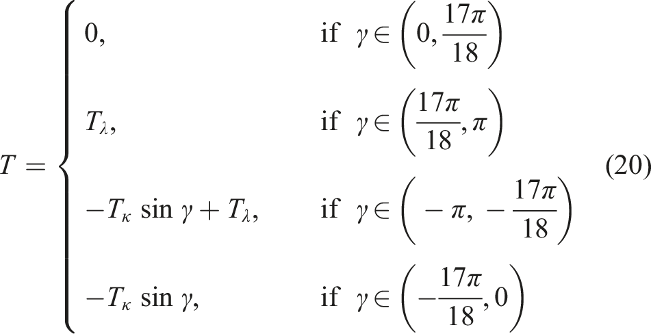
, the robot can initiate a rotation, aiding its transition from A-mode (clockwise rotation) resting state to T-mode resting state. The transition dynamics can be described about the equilibrium position as, (A) A schematic drawing of the transition from A-mode (clockwise rotation) to T-mode shown in three stages, projected in side view (looking from the root of the wing toward the tip). (B) A schematic drawing of the transition from T-mode to A-mode (clockwise rotation) is shown in three stages in isometric view. An initial thrust rolls the robot to an angle γ, followed by a turning maneuver that helps achieve the transition. (C) Front view of B(ii) and B(iii).
The robot leverages data from accelerometer to compute the γ and ζ angles and gyroscope to compute
3.3.2. Transition from terrestrial to aerial mode
As stated previously, the robot cannot produce a torque directly about y B , therefore, the transition from T-mode to A-mode cannot be achieved straightforwardly. While the robot is in T-mode, the z GC axis remains parallel to z C . Moreover, when the robot is turning, the y GC axis is maintained to stay parallel to the y C axis, to ensure maximum effective thrust to overcome the frictional forces. However, rolling the robot forward (or backward) to ensure that angle γ ≠ 0, followed by generating a torque about x GC , can help achieve the required transition.
Figure 4(B) depicts the transition from T-mode to A-mode (clockwise rotation) in three stages. In the first stage, the robot is in its passive equilibrium and it starts the transition by rolling forward. In the second stage, the robot applies reverse thrust to generate torque about x
GC
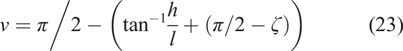
and in the third stage, the robot falls to its passive equilibrium position in A-mode. Figure 4(C) depicts the front view of the robot, before and after applying the required torque for transition. The value of ζ is maximum before the transition, where ζ = π/2. Once the torque is applied, angle ζ starts to decrease from π/2 → ζ0, which is the minimum value for the angle, constrained by the design. The torque is applied until the angle subtended by the gravity vector (ν) is negative. Describing the transition about the equilibrium position, we obtain

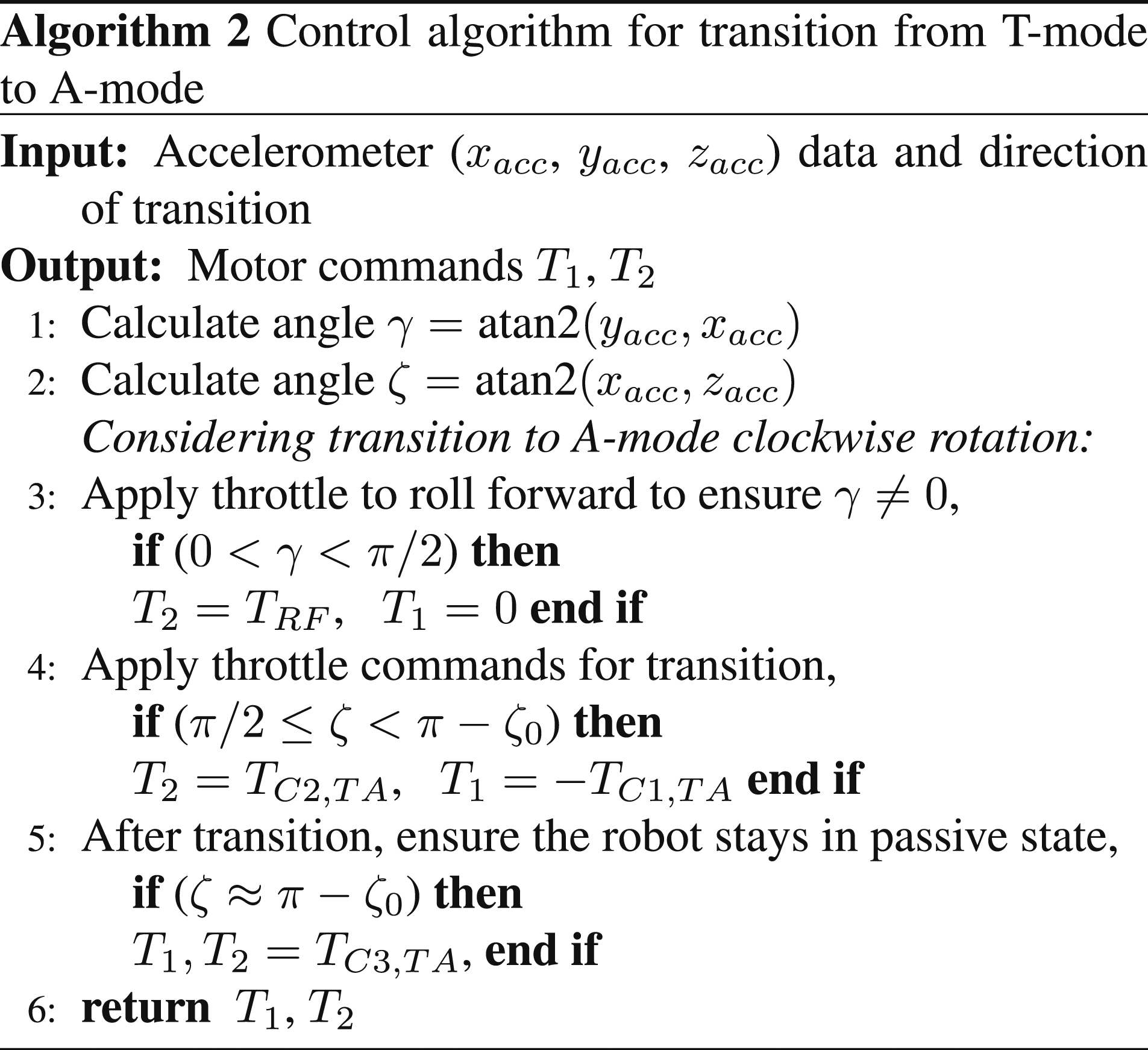
It should be noted that the transition can be performed in either direction, that is, to flip the robot left or right. Flipping left will result in the robot transitioning into A-mode clockwise rotation flight mode, and flipping right will result in the robot transitioning into A-mode counterclockwise rotation flight mode. A comprehensive algorithm description detailing the transition of the robot from T-mode to A-mode is provided in Algorithm 2 for ease of implementation. Within Algorithm 2, T RF represents the constant throttle applied for rolling forward; TC1,TA and TC2,TA are throttle constants utilized during the transition from T-mode to A-mode, and TC3,TA is the constant throttle applied to motors after transition to ensure the robot stays in the passive state.
Throttle is implemented on the two motors according to the final required direction of A-mode rotation. Considering the case of transitioning to A-mode clockwise rotation, throttle is directed to M2 to initiate the forward rolling of the robot. Once the robot has rolled forward by γ ≈ π/2, transition throttles are subsequently applied to both M1 and M2 to alter the angle ζ. Subsequently, a low magnitude throttle command is applied to both motors to initiate spin movement which ensures the robot remains in the passive state after the transition. It should be noted that for transition to A-mode counterclockwise rotation, the throttle commands for the two motors are switched in steps 3 and 4 in Algorithm 2. The overall control architecture of the robot is depicted in Figure 5. Control architecture of the robot with the input and output states.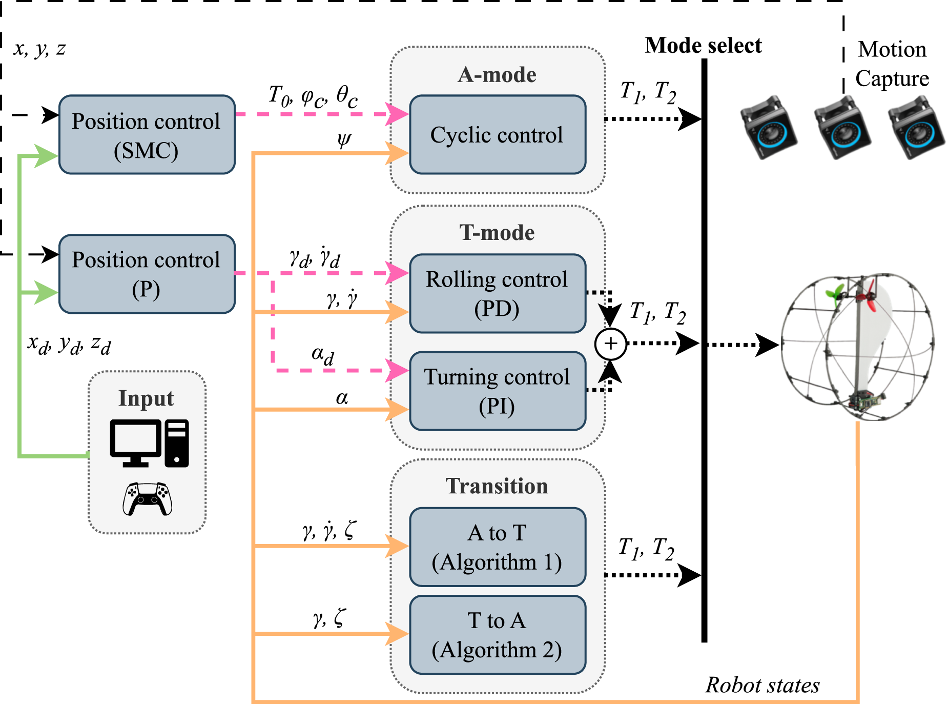
3.4. Selection of design parameters
The internal dimensions of the robot are predominantly governed by its frame diameter. An optimal frame diameter is crucial to balance the trade-off between wing size, ground movement resolution, and overall robot weight. A small diameter may limit wing size, impeding lift generation during A-mode, while a large diameter increases ground movement distance and weight, impacting motor load. Quantitative evaluation proves challenging due to the interdependence of these variables. Hence, an iterative testing and prototyping approach was employed for fine-tuning the frame diameter, wing size, motor, and battery weight.
Three frame sizes (0.25 m, 0.3 m, and 0.4 m) were tested, with 0.25 m rendering inadequate lift and increased rotational speed, while 0.4 m resulted in flight challenges due to added weight. The optimal choice was a 0.3 m diameter frame, addressing these issues and enhancing the overall efficiency of the robot. The wing profile of the robot was determined based on the frame diameter, as illustrated in Figure 6. The underlying concept is to maintain a relatively compact wing chord near the wing’s root while maximizing the wing area as it extends toward the wingtip. A drawing of the wing profile with key dimensions (in mm).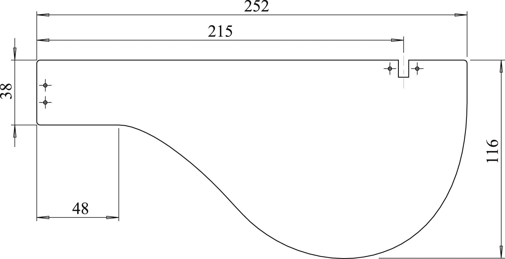
Inspired by the natural “Samara seed,” the mono-wing design incorporates a lighter wing with a heavier root side, mirroring the seed’s weight distribution. The battery, being the primary weight, is positioned at the root, while the motors are situated at the wingtip for efficient thrust. Motor selection involved assessing thrust requirements to counter the robot’s overall weight in flight. BETAFPV 1404 4500 KV motors were chosen, providing 160 g thrust at 50% throttle, paired with Flywoo 4S 300 mAh batteries to counterbalance weight.
A CAD model, constructed in SolidWorks with accurate weights and dimensions, aids in estimating the robot’s center of mass. This center of mass is located at the rotational axis, which can be tuned appropriately at this stage. However, it is intentionally kept toward the root of the wing by design, aiming to utilize the maximum wing area to generate lift during flight. It should be noted that in T-mode, the mono-wing design provides the advantage of achieving a lower CG, aiding T-mode’s passive stability.
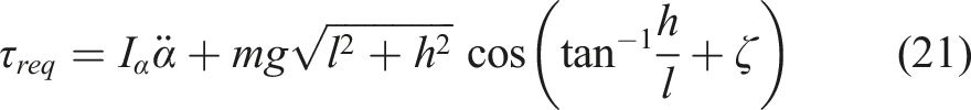
The arm length of the motors is selected to be the maximum possible, based on the shape of the frame; therefore, it depends on both h (distance of the center to the edge of the frame (depicted in Figure 3(C)) and ζ0 (angle formed by the frame segment on the upper and lower part of the frame). The selection of parameters ζ0 and h is based on the torque required during the transitions, as well as geometric constraints. During the transition, the maximum amount of torque is required at the beginning, when t = 0 and Variation of transition torque with varying values of frame parameters ζ0 and h.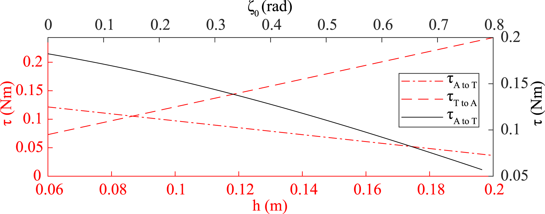
On the other hand, ζ0 only affects the transition from A-mode to T-mode. Considering the torque equation and varying the ζ values, it can be observed that as the value of ζ increases, the torque required for the transition decreases (Figure 7). The maximum value of ζ0 will depend on h and l1. Beyond this maximum value, any further increase will make it impossible for the robot to stay in passive equilibrium in A-mode on the ground. l1 is fixed based on the frame size and flight characteristics of A-mode, and is approximately equal to 0.08 m. Therefore, geometrically the maximum value of ζ0 ≈ 0.75 rad. For ATOM, this value was chosen to be π/6 rad, providing the robot some lenience to avoid exceeding the critical mark.
4. Experimental validation
This section covers the experimental setup used to conduct the indoor experiments and the results obtained for closed-loop position control for both A-mode and T-mode flights. Semi-indoor and outdoor experiments conducted and the results obtained for T-mode’s endurance and capability are also discussed.
4.1. Experimental setup
The OptiTrack motion cameras capture the position and attitude of the reflective markers mounted on the ATOM prototype with a frame rate of 180 frames per second. The OptiTrack data generated by the OptiTrack native application is subsequently imported into MATLAB through NatNet. NatNet serves as a software development kit designed for transmitting and receiving OptiTrack data over networks. After the MATLAB code computes the output commands for the actuators, these values are transmitted to the robot through a 2.4 GHz transmitter and receiver. A secondary RC transmitter, operated by a human, can also transmit control signals to ATOM, allowing it to override output commands from the PC when necessary.
4.2. Experimental results for flight tests
ATOM’s flight performance was tested in both clockwise and counterclockwise directions using A-mode. Figure 8 depicts the results for position hold for five different flights for both directions. Clockwise rotating flight is depicted by a negative Ω
z
value, whereas counterclockwise rotating flight is represented by a positive Ω
z
value. The robot can maintain its position while rotating at various rotational speeds in both directions. Nearly identical performance is obtained based on the results for the two cases. Position hold results for five different rotational speeds in clockwise (negative Ω
z
) and counterclockwise (positive Ω
z
) directions, along with the respective average throttle commands for the two actuators.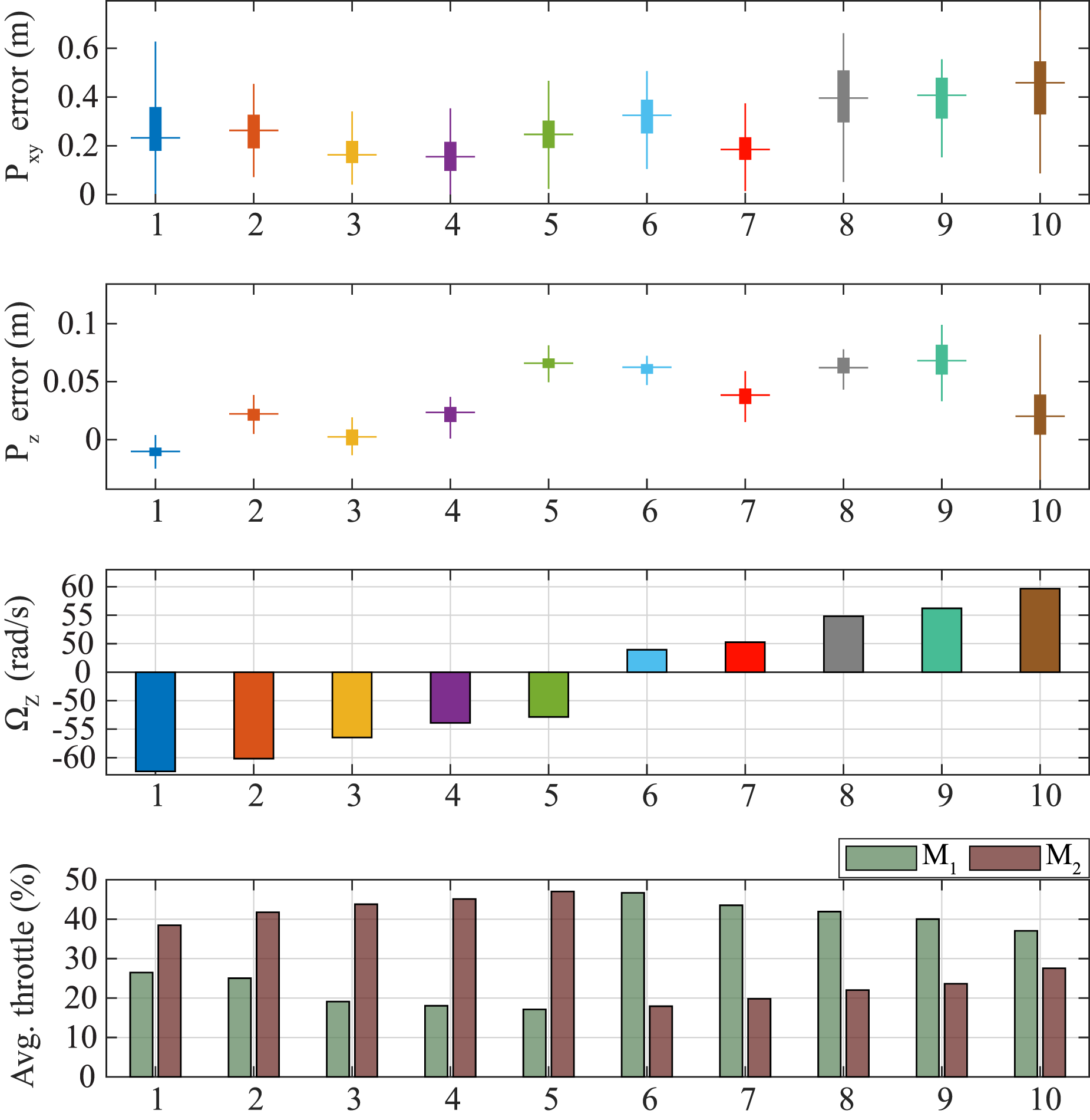
During the flight, the main motor controls the altitude and direction, and the other motor balances the torque. The torque balancing motor’s indirect effect is utilized to control the rotational speed to some extent. This is achieved by simply controlling the amount of counter torque provided to the balancing motor. For the clockwise rotation flight, M2 provides the majority of thrust for altitude and direction control, whereas, M1 provides the balancing torque. For the counterclockwise rotation flight, the roles of the motors are reversed. Tests were conducted to obtain the limiting values of the rotational speed, and the results are depicted in Figure 8. Results show that ATOM obtains the lowest position error and the best power efficiency rotating at approximately −50 rad/s clockwise and 50 rad/s counterclockwise. It should be noted that attaining perfect symmetry in the system’s design is often challenging. Consequently, minor disparities in the maximum and minimum rotation speed values are observed in both cases. However, since the difference is very small, the performance in both cases can be regarded as nearly identical. Supporting video S1 shows a side-by-side comparison of ATOM flying at two different rotation speeds.
Figure 8 also depicts the average throttle value (scaled from 0% to 100%) for both motors, for all cases. It can be observed that for both side rotations, the average throttle value for the main motor is approximately 40%, while the throttle value for the balancing motor ranges between 18 and 30%. In the case of clockwise rotation, an increase in throttle value for M1 results in an increase in rotational speed, but for M2 the opposite applies because additional effort is required at lower speeds to maintain altitude.
To test the closed-loop position tracking performance, ATOM is tasked to fly in a 2 m side square-shaped trajectory, changing the desired position incrementally at each time step. Alongside, the position in the Z axis is changed continuously as well. Figure 9 depicts the results obtained. Overall, satisfactory results are obtained while tracking the trajectory. A Root Mean Square (RMS) error value of 0.11 m is obtained, while tracking the trajectories in both directions. Figure 9(C) depicts the controller output vector Closed-loop position tracking results for A-mode in (A) clockwise rotation, and (B) counterclockwise rotation. (C) Scaled controller output 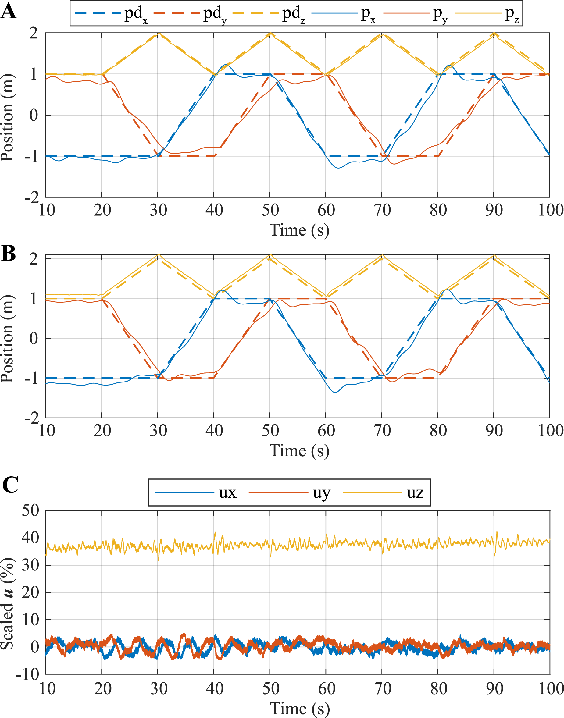
Figure 10 illustrates the heading angle (ranging from 0 to 2π) and the angular velocity over a short time period. While the heading angle values do not consistently remain within the range of 0 to 2π in each cycle, the resolution is adequate for manually controlling the robot’s position in outdoor environments. The yaw rate depicted in Figure 10 is obtained by differentiating the yaw angle. Yaw angle and yaw velocity variation over a short period of time.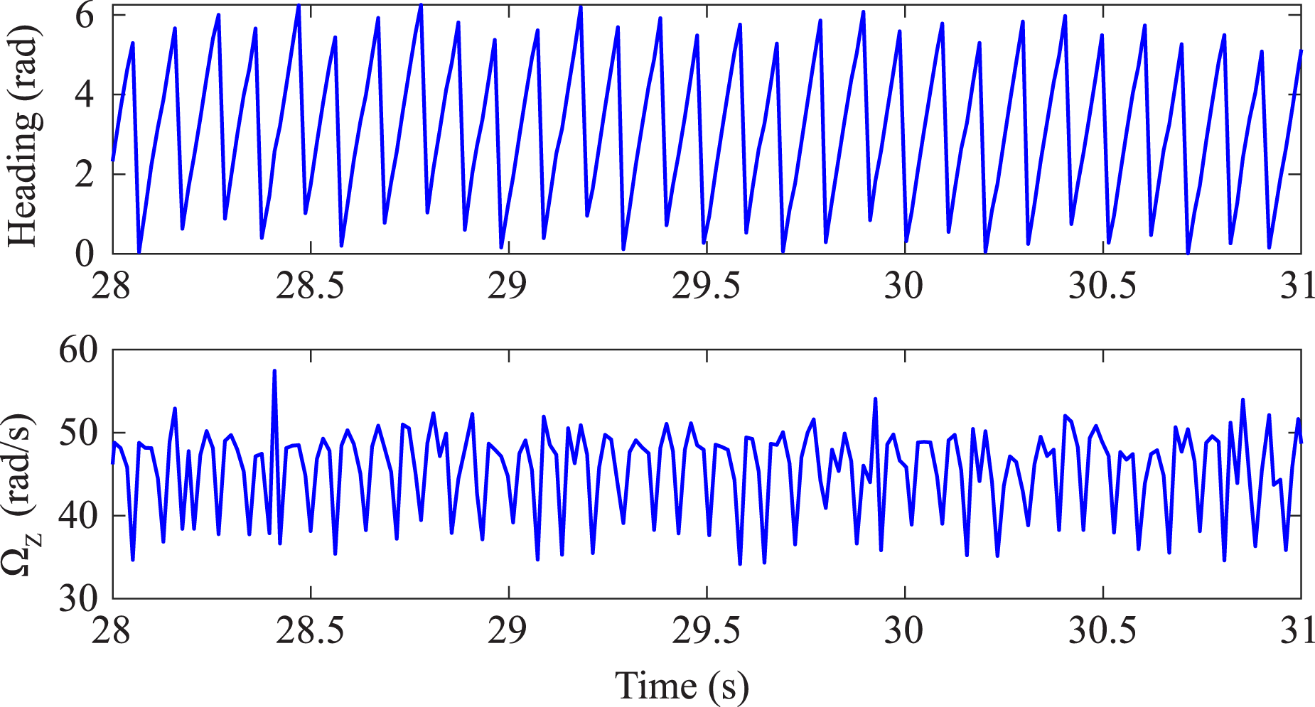
4.3. Experimental results for terrestrial locomotion
Various tests were conducted to verify the performance in T-mode. As described in the previous section, the basic motions of rolling and turning are achieved by providing thrust from the motors together in the same and opposite directions, respectively.
4.3.1. Start and stop rolling
Figure 11 depicts three different stages of ATOM in T-mode. To start rolling from a stationary position (Figure 11(A)), the desired minimum torque is calculated using equation (18). The throttle value is incrementally increased from t = 0 s to t = 1.0 s to ensure synchronization of both motors. This gradual increase in throttle, as opposed to a sudden change (e.g., using a step function), is implemented to prevent any abrupt jolts that could lead to unintended changes in the heading. The robot applies about 20% throttle to start the roll motion. From t = 1.0 s to t = 5.3 s, the robot is in roll state, where thrust required to continue rolling is calculated using equation (19). Throttle is applied to the robot once the angle γ exceeds −π radians (as shown in Figure 11(C)). This threshold also corresponds to the point where the angular velocity, represented as Results depicting various stages of ATOM in T-mode.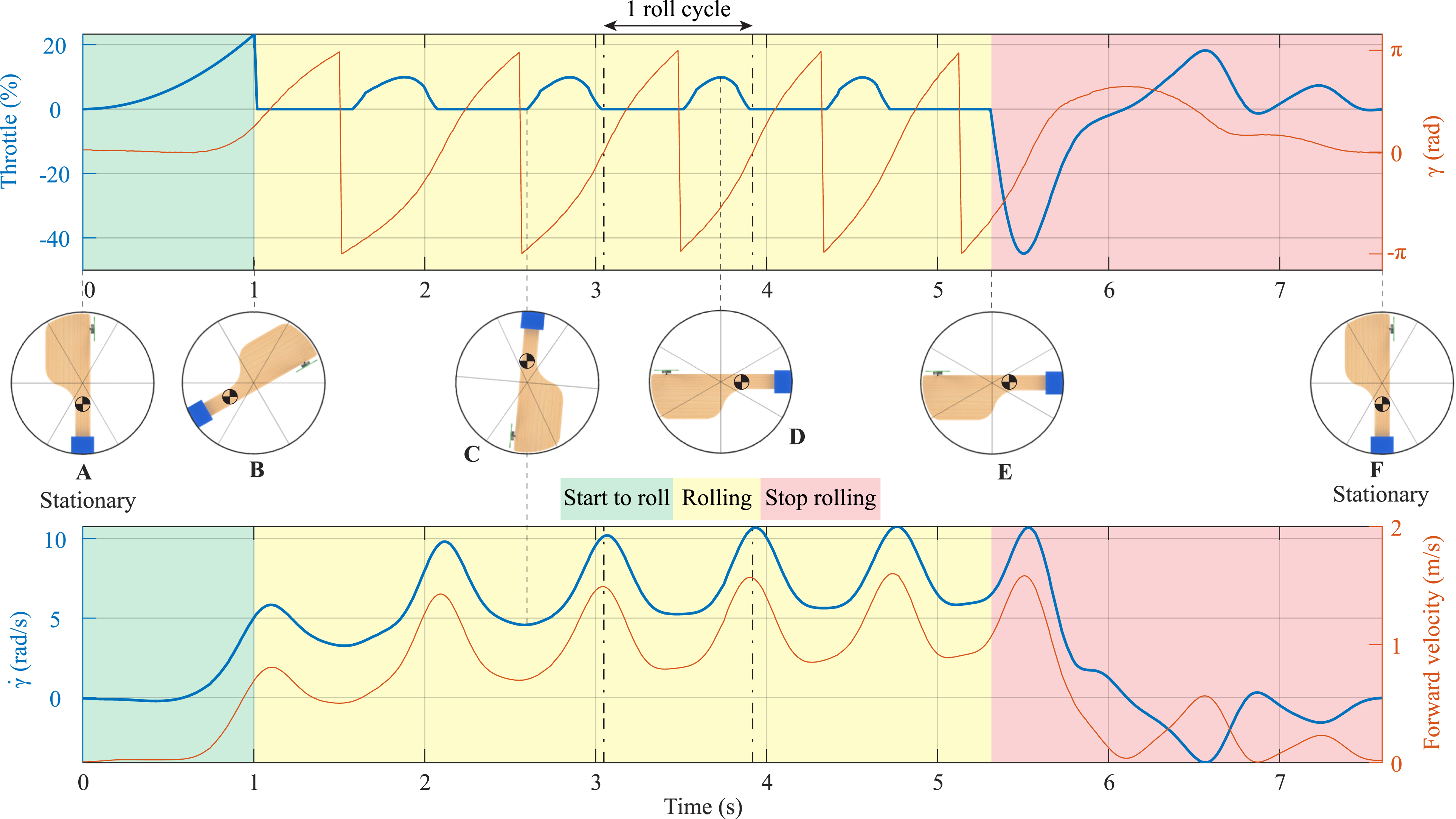
4.3.2. Heading control
The turning control of T-mode governs the heading of the robot between 0 and 2π radians. The heading control works in parallel with the roll control, which ensures that γ ≈ 0 rad. This coupled roll and heading control is tuned carefully to ensure a stable turn while keeping the roll oscillations minimized. Figure 12 depicts the results of the closed-loop heading control experiment performed, with ATOM receiving heading feedback from motion capture cameras. In the experiment, ATOM is tasked to turn by π/4, π/2, 3π/4, and π rad at equal intervals on an EPA foam surface. The results from four different tests showcase the robot’s consistent ability to follow the desired heading. However, variations become apparent, especially when the required angular change is high. In such cases, the time taken by the robot to align with the desired angle varies among the four tests. Additionally, a small overshoot can be observed in some cases, which is due to integral error built up. The results yielded an RMSE error of approximately 0.76 rad, accompanied by a steady-state angular error of approximately 0.03 rad. Closed-loop heading control experiment results for four tests.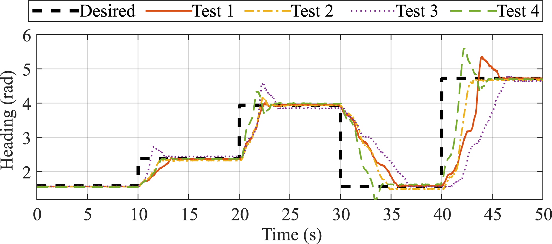
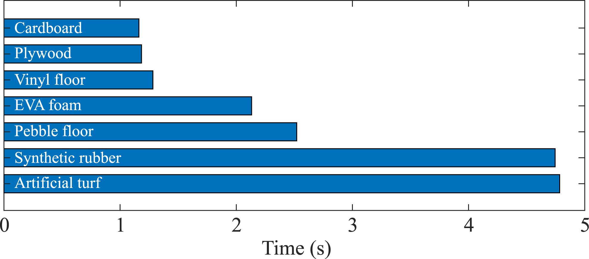
Tests were conducted on various surfaces to evaluate the robot’s rolling and turning capabilities (as depicted in Figure 13 and Supporting video S1). Since the turning motion is influenced by the frictional coefficient between the ground and the robot, theoretically, it requires more effort to turn on rough surfaces. Figure 14 depicts the results obtained for taking a 360° turn on different surfaces, keeping the same thrust value. It is important to note that this experiment was performed in an open loop, and the average time for 20 repetitions is calculated based on the recorded videos. Additionally, it is worth mentioning that the throttle amplitude used for turning in these experiments is notably higher compared to the closed-loop experiment mentioned previously. This was done to assess the minimum time required for a full turn on diverse surfaces, which have a considerable difference in their frictional coefficients. Smooth surfaces like vinyl flooring, plywood, and cardboard do not provide much resistance to the rims of the frame, therefore, the robot is able to turn much faster compared to non-skid flooring surfaces like EVA foam, pebble flooring, and synthetic rubber track. Although ATOM is capable of turning on different surfaces, it is unable to turn on thick grass due to the stems and blades of grass hindering any motion of the frame altogether. However, it can effectively turn on evenly-cut grass, such as artificial turf. Overlaying frame captures depicting the robot’s capability to traverse on different indoor and outdoor surfaces. Time taken by ATOM to turn 360° on different surfaces with the same throttle setting. The results were derived by averaging values obtained from 20 repetitions.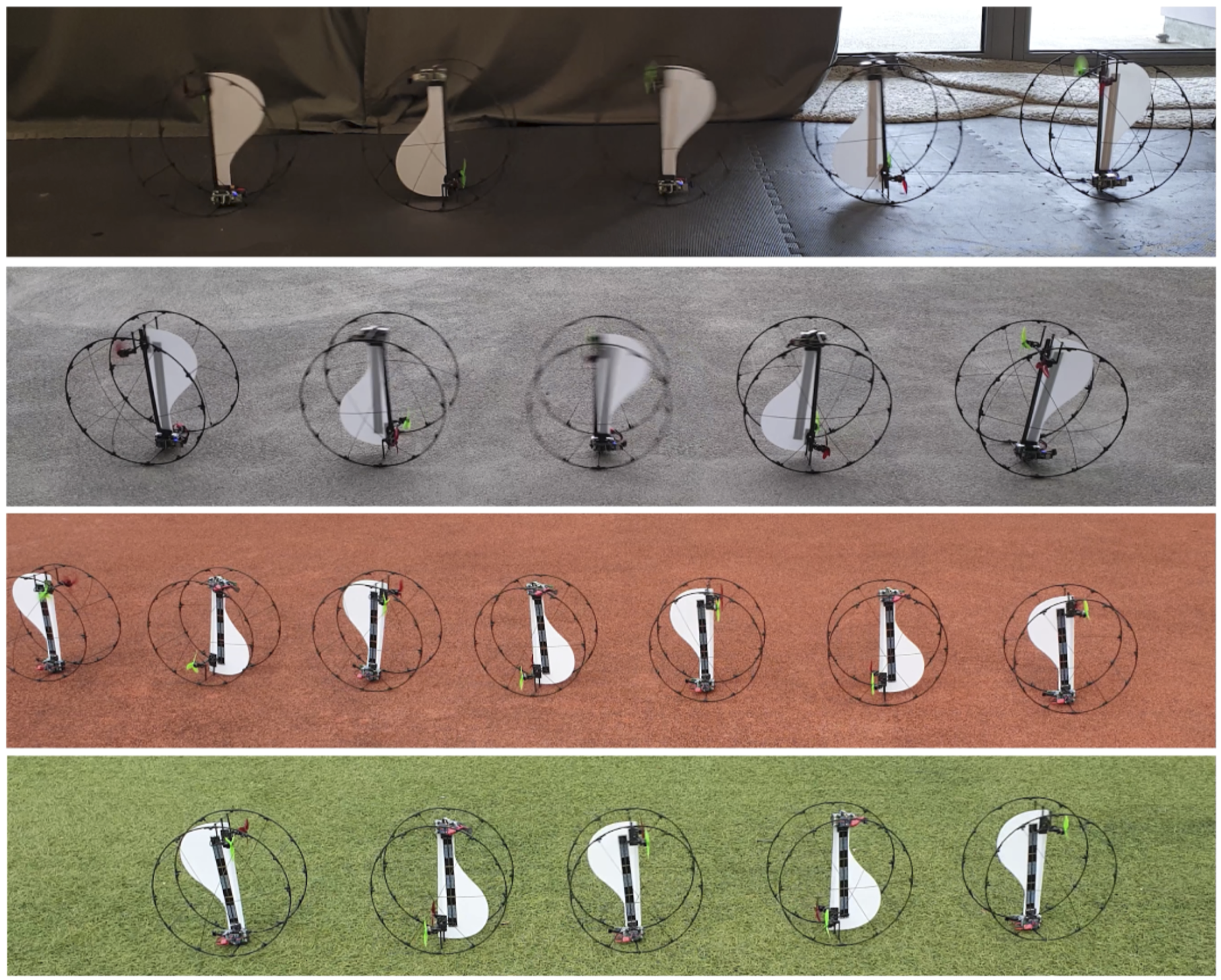
4.3.3. Position tracking
To test the closed-loop position tracking in T-mode, ATOM was tasked to follow waypoints forming a square shape of side 2 m (demonstrated in Supporting video S1). Each waypoint is given some tolerance to overcome the design constraints and allow T-mode to return to its passive equilibrium position, before continuing to the next waypoint. Figure 15(A) depicts the results obtained from 12 runs of the robot navigating around the square shape. The boundary of maximum and minimum error values at each step was established based on the outcomes of these 12 experiments, and these boundaries are visually highlighted with dashed lines in Figure 15(A). Additionally, a solid line plot illustrates the mean values derived from the experiments. In specific instances, the average line aligns with the maximum or minimum boundary, indicating that most of the results follow that path. From the results, it can be observed that ATOM can consistently and almost accurately follow waypoints while in T-mode. An RMS error value of 0.19 m was obtained for the results. Figure 15(B) depicts throttle values of the two motors for two sides of the square. In addition to the start-to-roll, roll, and stop-rolling phases where the throttle values overlap, it is noteworthy that during the turning phase, the motors are actively applying throttle in opposite directions while simultaneously controlling the roll angle γ. A small time difference between both turns can be noticed in the results, which can be attributed to an uneven amount of friction across the floor. Implementing velocity feedback during turning can overcome this issue and will be addressed in future research. (A) Closed-loop position tracking results for T-mode following waypoints. Dashed lines represent the boundary of maximum and minimum results obtained for 12 runs. The region has been color-coded to represent the start of rolling, rolling, and stopping regions, while the blue circles represent the tolerance region for stopping. (B) Scaled throttle (−100% to 100%) for a section of results, depicting the robot going around two sides of square-shaped waypoints.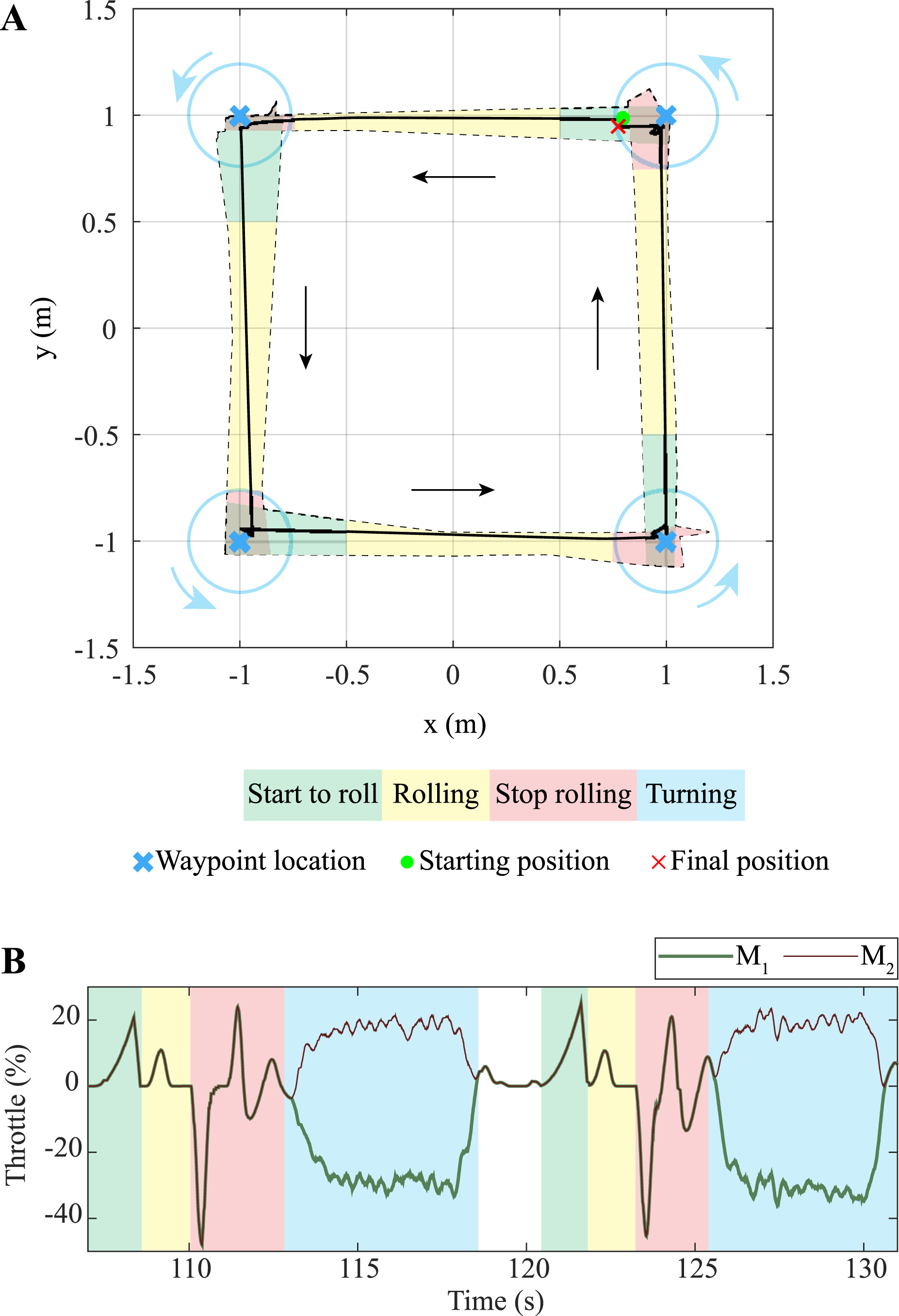
To evaluate ATOM’s ability to execute turning and rolling without stopping, it was tasked to track three waypoints. After navigating the first two waypoints of the square shape from the previous experiment, ATOM was then directed to initiate a turning maneuver while rolling forward toward the initial starting point. This creates a quadrant of radius 2 m, as illustrated in Figure 16(A). The experiment was conducted eight times, and the results are presented in consistency with the previous experiment. It is crucial to emphasize that the robot’s final stopping position may not align precisely with the designated waypoint due to inherent design constraints discussed in the previous section. Nevertheless, even with these constraints, an RMS error of only 0.2 m was achieved. Figure 16(B) depicts the roll angle γ (from −π to π radians) and heading angle α (from 0 to 2π radians) of the robot, along with the angular rates for the experiment. It is imperative to maintain a low turn rate during the turn-while-rolling maneuver to prevent the risk of flipping, as seen in the results. The turn-while-rolling maneuver of ATOM is demonstrated in Supporting video S1. (A) Cumulative results for the turning-while-rolling maneuver in T-mode, derived from eight repetitions. Color coding from Figure 15 is applicable, with the addition of three arrows showing turning while rolling. (B) Roll and heading angles with corresponding angular rates.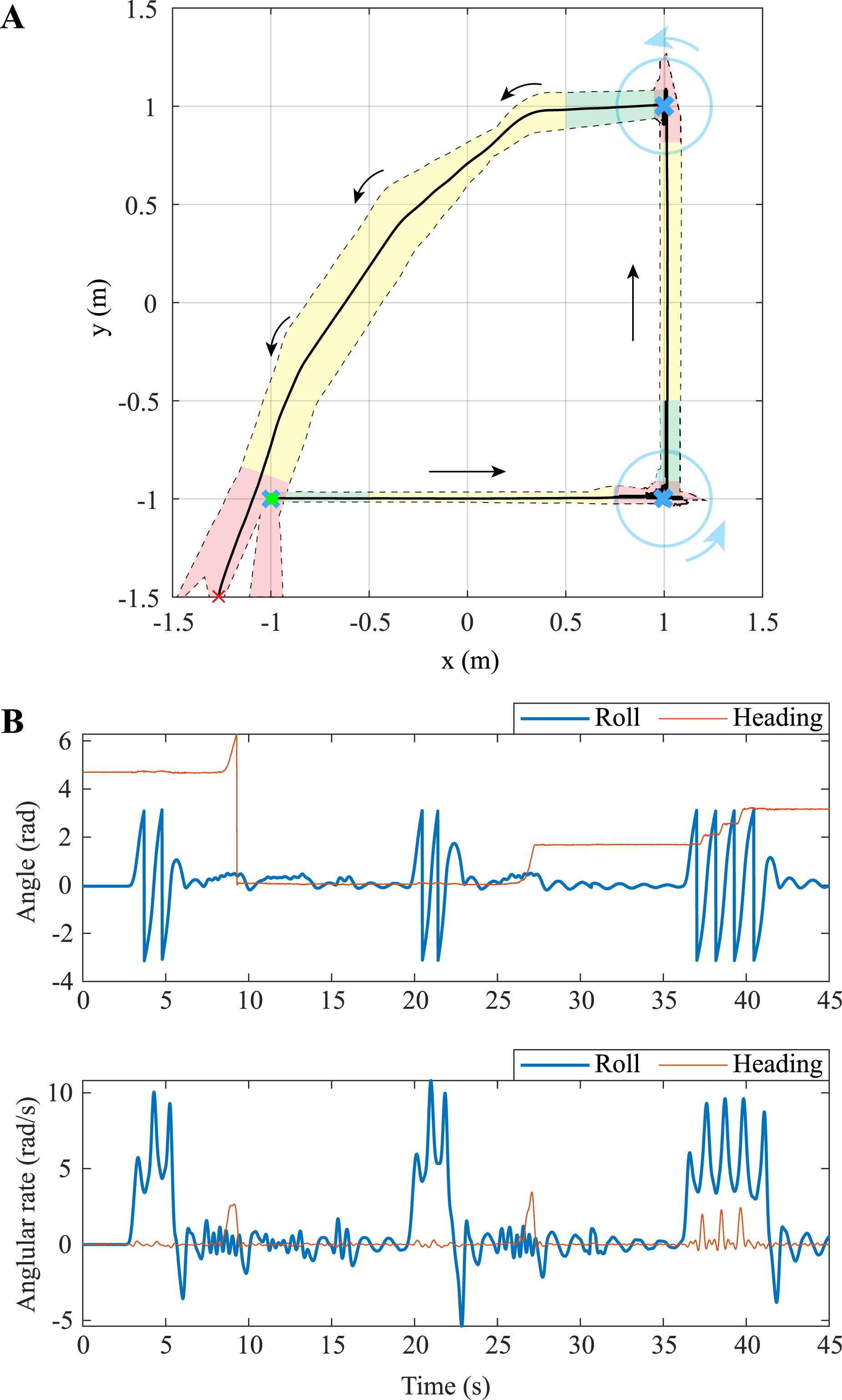
4.3.4. Performance on inclined surfaces
In addition to flat surfaces, ATOM can ascend and descend inclined surfaces. The robot was tested on inclined planes with inclination of up to 15°, which represents its maximum limit. Beyond this value, the robot struggled to maintain sufficient traction with the ground, resulting in slipping rather than ascending. However, this issue did not occur during descent, as the robot simply rolled down the incline. The robot’s performance was tested using two different rolling methods. The first method is continuous rolling, where ATOM continuously rolls up or down the inclined surface without interruption. This is the most direct and efficient way to navigate inclines. The second method is incremental rolling, where ATOM moves in discrete, incremental steps while ascending or descending the inclined surface. It completes one cycle of roll, comes to a stop, repeats the process, and so on. This approach is comparatively less efficient but may be necessary in specific situations where the robot needs to pause on an inclined surface. ATOM’s controlled ascent and descent on an inclined surface are demonstrated in Supporting video S1.
Figure 17 depicts the scaled throttled values and roll angle rate of the robot for various tested scenarios. In case of continuous ascent, the robot begins rolling from a shallower inclination and progressively ascends. For incremental ascent, the value of Tp,d is adjusted to facilitate a quicker initial roll, enabling the robot to overcome external forces. In this scenario, the primary roll action is accomplished by the initial throttle, propelling the robot forward. Results of ATOM on an inclined plane for (A) continuous ascent, (B) incremental ascent, (C) continuous descent, and (D) incremental descent. Non-highlighted sections of the plots depict the region where ATOM is holding its position without rolling up or down. (E) Frame captures from a video depicting the robot doing incremental ascent.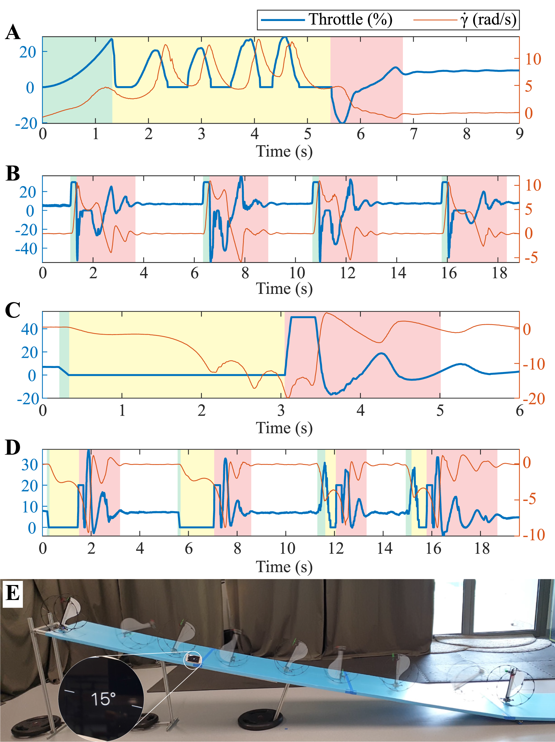
Owing to its distinctive design, ATOM exhibits the ability to maintain its position on an inclined surface with minimal throttle input. This is made possible by its lower CG, which enhances its passive stability. During descent, ATOM simply disengages the throttle and descends under the influence of gravity. Despite gaining a high velocity by the end of the ramp
4.3.5. Ground velocity
The frame of the robot is rigid enough to support locomotion on the ground. However, its lightweight design using bare essential supports restricts the robot from achieving very high speeds on the ground. Basic tests were performed to evaluate the ground speed of the robot by recording the angular velocity of the robot using the onboard IMU. The maximum speed ATOM achieved on the ground in T-mode is approximately 2 m/s. While this velocity may be less than that reported in some studies (e.g., Dudley et al. (2015); Pan et al. (2023)), it equals or surpasses the performance observed in other notable works in the literature (e.g., Pratt and Leang (2016); Zhang et al. (2022); Qin et al. (2020)).
4.4. Transition from one mode to another
Transitions between the two modes are designed based on the attitude feedback of the robot from IMU onboard, independent of any position feedback from the motion capture cameras (as shown in Supporting video S1).
The transition from A-mode to T-mode was tested with robot lying on the ground in both rotation modes. Due to the robot being a highly under-actuated system, the transition is designed to orient the robot from one passively stable equilibrium position to the other. Therefore, the final heading of the robot is not considered a constraint, as it can be controlled after transition. Additionally, after transitioning to T-mode, the robot is programmed to utilize its roll control to stabilize quickly to its passive state, rather than relying on its natural damping. Figure 18 depicts transition of the robot from A-mode to T-mode. It can be observed that the robot takes less than 1 s to finish the transition and subsequently, approximately 2–3 s to stabilize to its passive state. During the process of transition, both motors provide thrust to the robot until it crosses the threshold ζ angle, after which T-mode controller takes over and stabilizes the robot. Frame captures depicting the transition of ATOM from A-mode to T-mode, starting with A-mode in (A) clockwise and (B) counterclockwise rotation. (C) Plot depicting the throttle commands along with angle ζ for counterclockwise rotation case.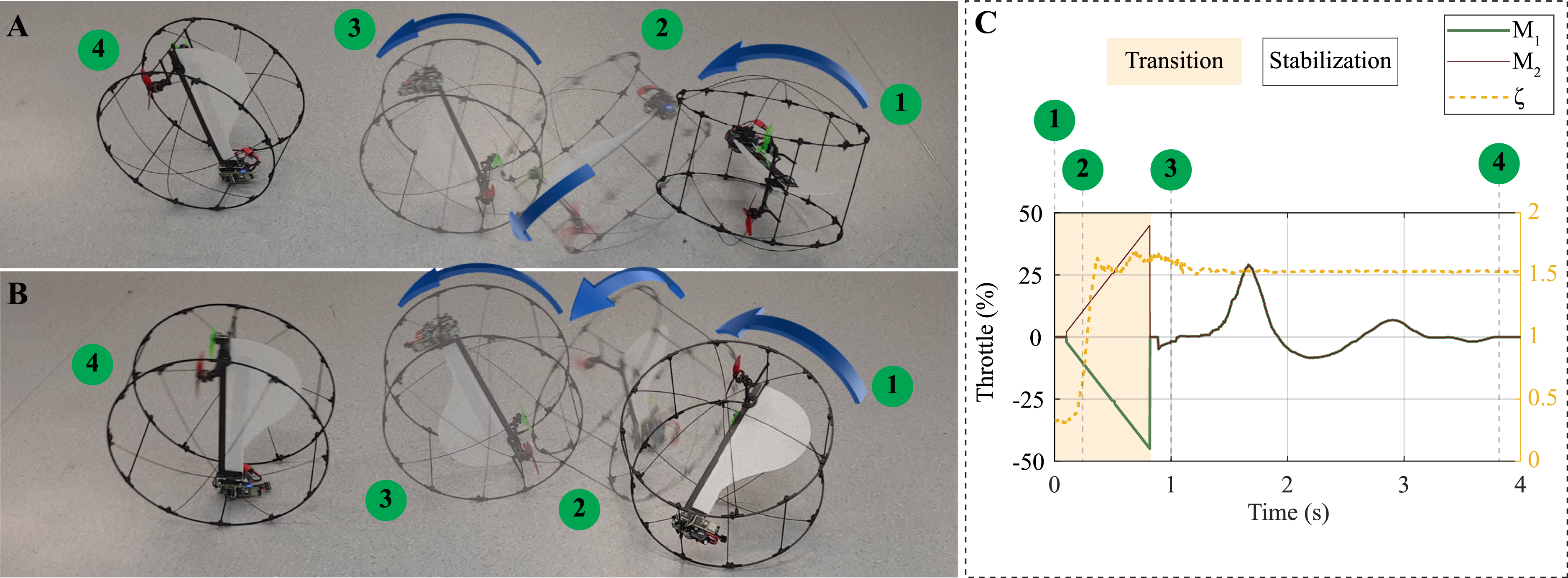
The transition from T-mode to A-mode initiates with the robot in a passive state. The final heading of the robot is inconsequential in this context since the final state is a rotating mode of aerial flight. Figure 19 depicts the ATOM transitioning from T-mode to A-mode in (A) clockwise and (B) counterclockwise rotation mode flights. Figure 19(C) depicts the throttle commands and angle ζ. It is important to emphasize that the transition to either clockwise or counterclockwise rotation mode is entirely under control and predetermined. ATOM completes the transition for both directions in approximately 2 s. To minimize the risk of transition failure and encourage the robot to assume the A-mode passive position, it is permitted to momentarily rotate after transitioning to A-mode (i.e., when ζ = ζ0). Frame captures depicting the transition of ATOM from T-mode to A-mode, ending with A-mode in (A) clockwise and (B) counterclockwise rotation. (C) Plot depicting the throttle commands along with angle ζ for counterclockwise rotation case.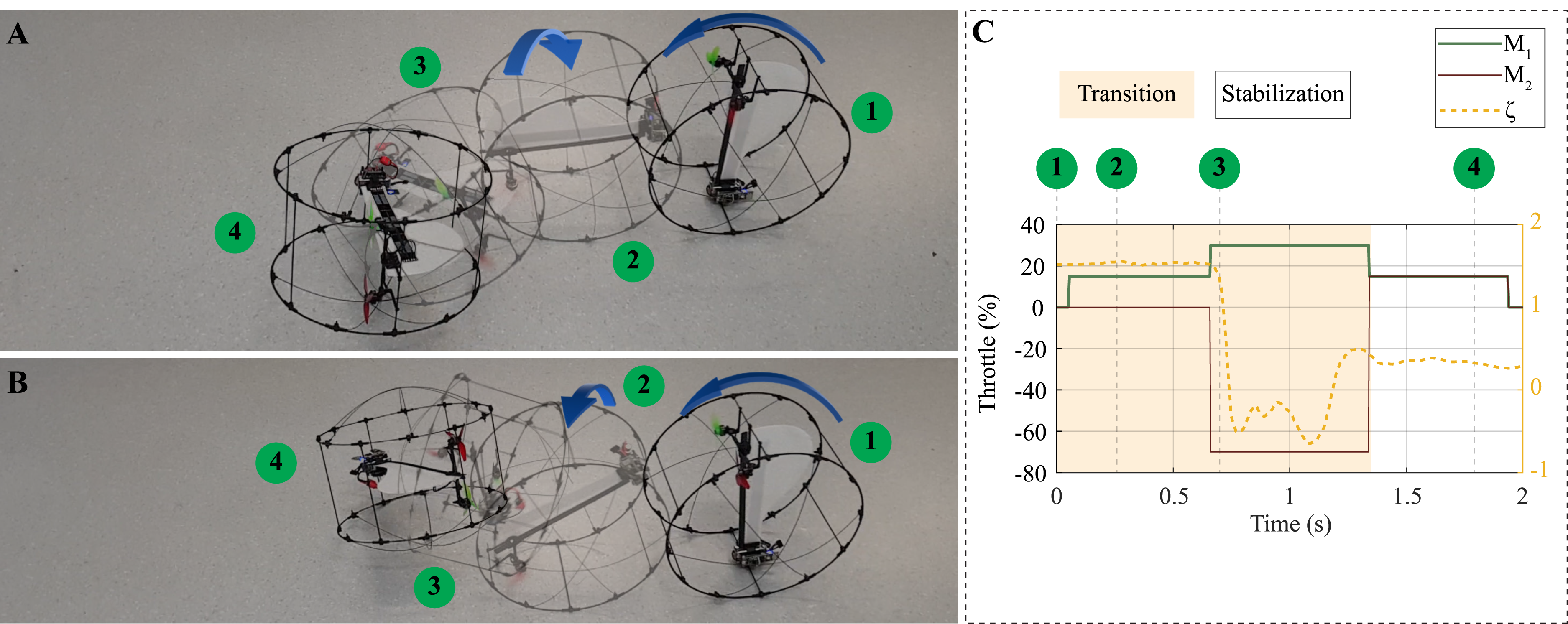
Both transitions were tested 20 times each on various surfaces, including vinyl flooring, plywood, cardboard, and EVA foam. Perfect transitions were achieved on all surfaces, except for EVA foam, where the A-mode to T-mode transition failed once, and the T-mode to A-mode transition failed four times. Across these repetitive tests, success rates of 99% and 95% were attained for the transitions from A-mode to T-mode and T-mode to A-mode, respectively. The failure in the transition from T-mode to A-mode was partly due to the inherent springy nature of the frame, which bounces the robot back to T-mode. Even though this failure is inconsequential, further tuning of gains can be done to mitigate this.
4.5. Power consumption
Each mode was tested to determine the time and distance until a 300 mAh battery was depleted from 98% to 10%. In A-mode, ATOM flies for approximately 4.8 minutes and has an average range of 432 m. The average current drawn is 4.5 A. The maximum linear velocity achieved during flight is around 1.5 m/s. In comparison, in T-mode, ATOM travels for 44.28 minutes and has a range of 3.78 km. The average current drawn is 0.38 A while rolling at a constant velocity. The maximum linear velocity achieved by ATOM during ground locomotion is around 2 m/s.
A summary of the average power consumed during different phases is illustrated in Figure 20. Notably, power consumption during stopping and turning phases in T-mode is higher than in the other phases. Similarly, comparing the two transitions, the transition from T-mode to A-mode results in higher power consumption. This is because these phases and T-mode to A-mode transition rely on conventional propellers to generate reverse thrust for a significant duration. Typically, conventional propellers (like the ones used in this research) are optimized for producing thrust in a single direction, making them less efficient when used in reverse. Average power consumed by ATOM in different modes. Abbreviations: CU = continuous uphill; IU = incremental uphill; ID = incremental downhill; A to T = aerial to terrestrial; T to A = terrestrial to aerial.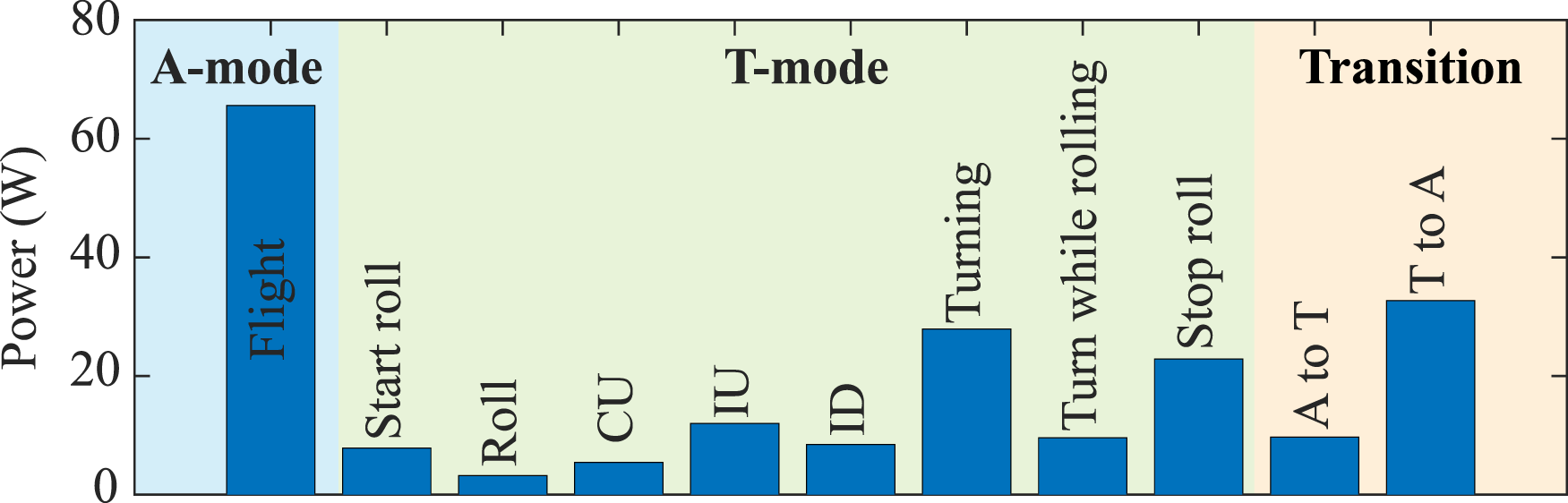
Hence, the robot is better suited for missions that involve long-range ground travel with minimal stopping and turning requirements. Alternatively, the turn-while-rolling capability can be leveraged, which can significantly reduce energy consumption.
5. Discussion
Comparison of aerial and terrestrial performance of state-of-the-art hybrid robots.
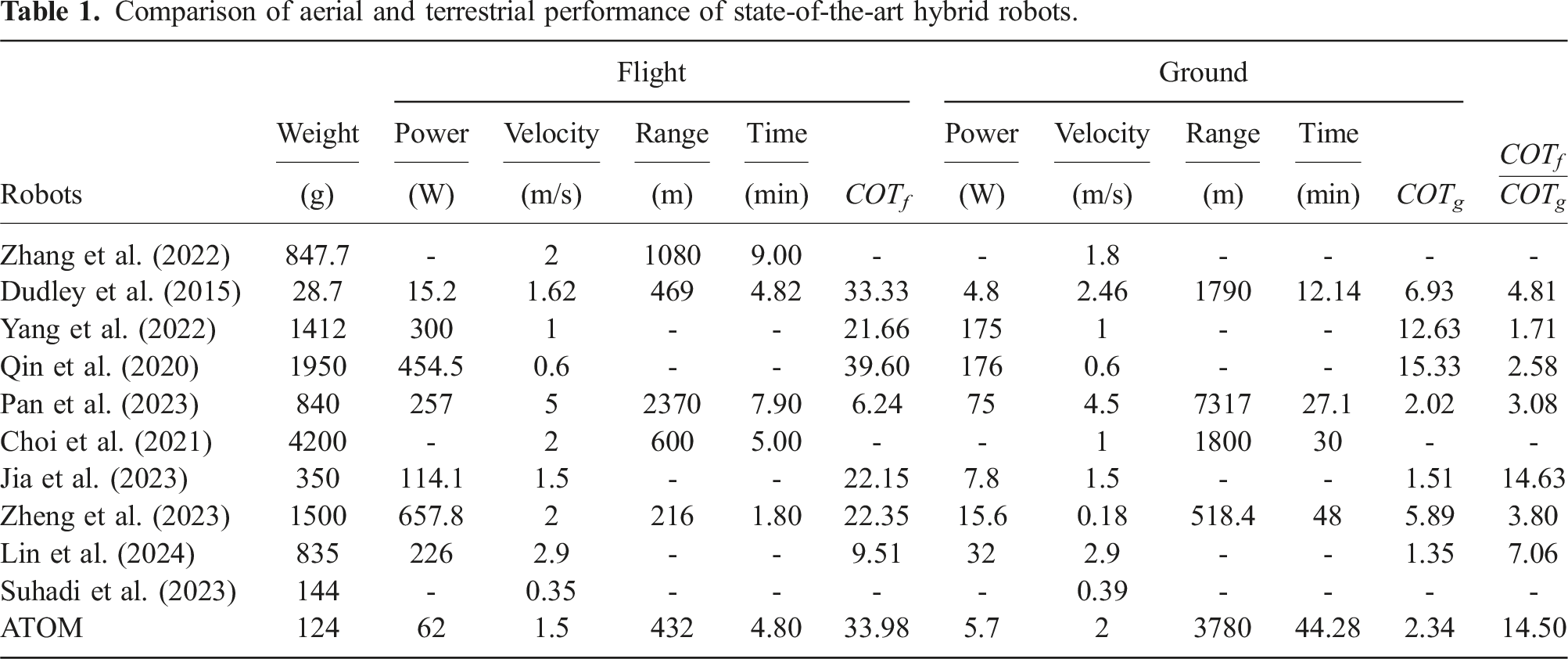
5.1. Maximum velocity
The maximum linear velocity achieved by ATOM during flight is approximately 1.5 m/s. While this velocity is lower than those reported in some studies, such as Pan et al. (2023), Zheng et al. (2023), and Lin et al. (2024), it is comparable to or surpasses the performance of other notable works, including Dudley et al. (2015), Yang et al. (2022), Qin et al. (2020), Jia et al. (2023), and Suhadi et al. (2023).
The maximum ground speed achieved by ATOM in T-mode is around 2 m/s. Although this velocity is lower than that of some hybrid robots, such as those reported in Dudley et al. (2015), Pan et al. (2023), and Lin et al. (2024), it matches or exceeds the ground speeds documented in other studies, such as Pratt and Leang (2016), Zhang et al. (2022), Yang et al. (2022), and Qin et al. (2020).
5.2. Range and operating time
In A-mode, ATOM can fly for approximately 4.8 minutes with an average range of 432 m. While this range and operational time are significantly lower than those of traditional quadcopter-based hybrid robots reported in Zhang et al. (2022) and Pan et al. (2023), they are comparable to or exceed the results presented in Dudley et al. (2015), Yang et al. (2022), Zheng et al. (2023), and Suhadi et al. (2023).
In T-mode, ATOM demonstrates an operational endurance of approximately 44.28 minutes, covering a range of 3.78 km. Compared to the works in the literature, Pan et al. (2023) reported a higher range, whereas ATOM surpasses the range and operational time reported in Dudley et al. (2015), Choi et al. (2021), and Zheng et al. (2023).
5.3. Efficiency
Another key metric often used in the literature to evaluate robots is the dimensionless Cost of Transport (COT = P/mgv, where P is the power consumed, m is the mass, g is the gravitational constant, and v is the velocity of the robot) based efficiency. For ATOM, the COT in A-mode is 33.98, while in T-mode, it is 2.34, indicating that T-mode is approximately 14.5 times more efficient than A-mode. When compared with other hybrid robots, ATOM’s COT-based efficiency is second only to the robot described in Jia et al. (2023), which achieves a COT of approximately 15. Nonetheless, ATOM’s efficiency surpasses that of other works, including Dudley et al. (2015), Yang et al. (2022), Qin et al. (2020), Pan et al. (2023), Zheng et al. (2023), and Lin et al. (2024).
5.4. Versatility
Only a few works in the literature have demonstrated comprehensive indoor and outdoor experiments on diverse terrains (e.g., David and Zarrouk (2021) and Jia et al. (2023)), and even fewer have showcased real-world applications. In contrast, we have conducted extensive testing of our robot in both indoor and outdoor environments, including a practical real-life scenario. Furthermore, we have demonstrated the robot’s ability to ascend and descend slopes of up to 15° using two different control methods. ATOM is also designed to eliminate any non-recoverable modes, an aspect that is often neglected in the designs presented in the existing literature. This feature is further elaborated later in this section.
Besides the experiments conducted in the lab, ATOM underwent extensive field testing to validate its performance in various challenging environments. Its adeptness in outdoor navigation and operation ensures reliability in executing application-based tasks.
As illustrated in Figure 21(A), a camera can be attached to ATOM to capture images/videos and store them onboard or transmit a live video feed remotely to a ground station. By controlling the roll angle γ within the range of (−π/3, π/3), ATOM achieves a comprehensive vertical field of view exceeding 180° with the camera. This allows ATOM to be used for close inspection of objects on the ground and at elevated heights (as highlighted in Supporting video S1). Similarly, ATOM can be employed for surveillance and infrastructure mapping, as shown in Figure 21(B) and Supporting video S1, where the robot rotates 360° while maintaining two different roll angles, 30° apart. The experiment yielded a panoramic image depicted in Figure 21(C). (A) Overall field of view of ATOM. (B) ATOM with an onboard camera recording the surroundings. (C) A panoramic image produced by stitching frames of video captured by ATOM.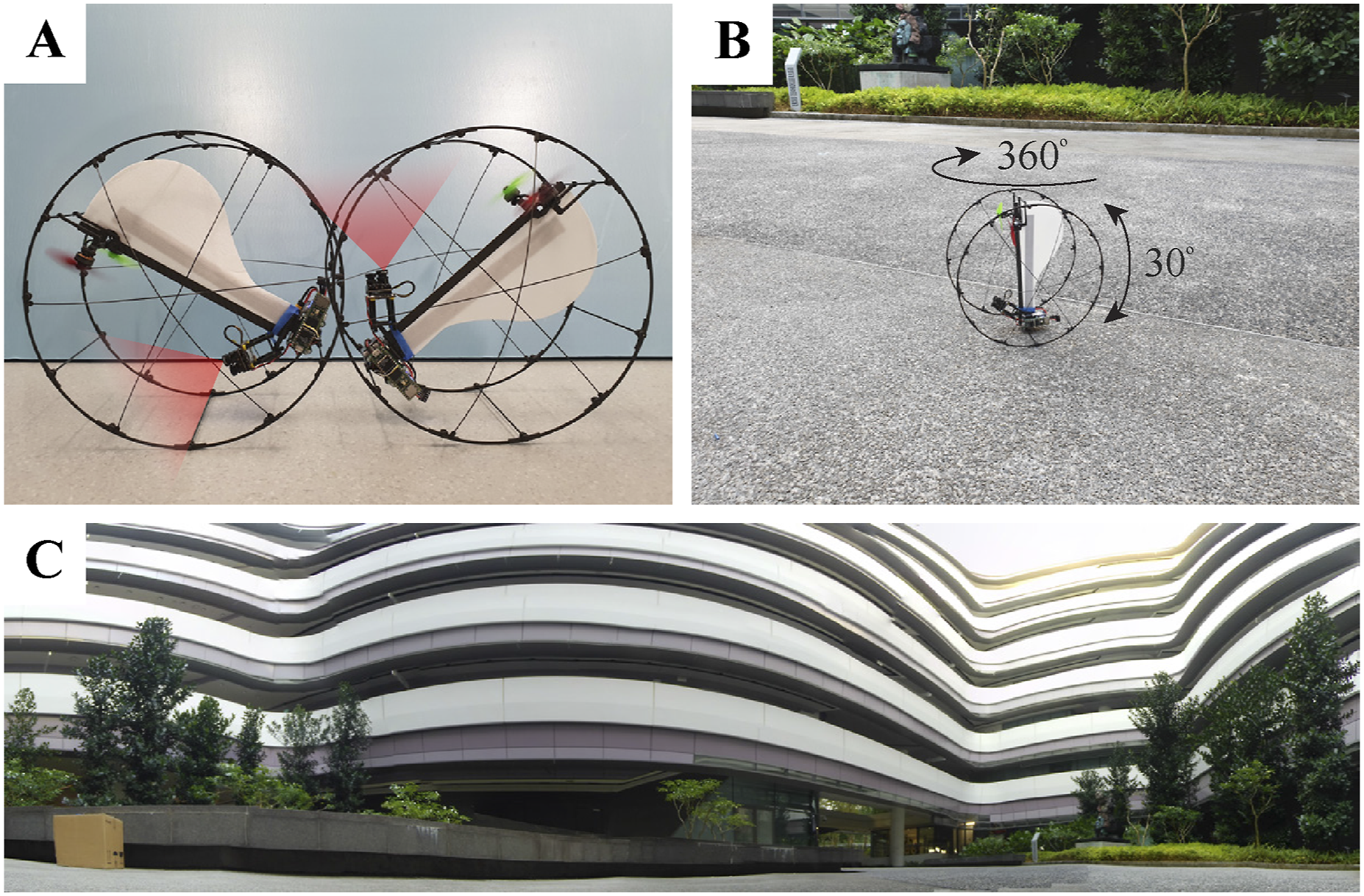
While rolling forward on the ground, ATOM may struggle to provide continuous visual feedback due to its highly under-actuated design and rolling nature. This limitation can be overcome by synchronizing the camera frames with the rotational rate of the robot. Additionally, this synchronization of camera frames can also be used for obtaining video feedback during the rotational mode flight, as done in Bai et al. (2022). By employing this method, a single onboard camera can efficiently capture a 360° video for surveillance purposes.
Simultaneous Localization and Mapping (SLAM) (Tan et al., 2021b) and autonomous navigation (Chen et al., 2023) can be achieved by mounting a single-axis laser or Light Detection and Ranging (LiDAR) sensor onboard. Environmental monitoring and deployment of sensors in remote areas are some of the other applications where ATOM can be utilized. ATOM can also be used for post-disaster search and assessment, navigating through confined spaces and flying over obstacles to map and inspect damaged areas. Its lightweight and collision-tolerant design makes it ideal for unstable, cluttered environments. However, this robot may not be the ideal choice for precision position-holding applications, such as precision agriculture for planting and harvesting crops or material handling in factories and warehouses.
The bi-directional rotation capability offers the versatility of using the robot’s body for various purposes. It enables the mounting of different sensors on the top and bottom of the robot, which can be strategically utilized depending on the specific mission phase. Further exploration and research into this feature will be a focus of our future research. Additionally, the bi-directional rotation capability serves as a fail-safe in situations where the drone may fail to land as intended. Typically, if a drone lands upside down due to an error, it would be unable to correct itself. However, the unique design of ATOM ensures that it does not have an unrecoverable state (e.g., upside down). This feature proves invaluable in scenarios where drones are deployed in remote or inaccessible locations, where human access is impractical due to high costs or time constraints for retrieval.
Supporting video S1 highlights key features of ATOM’s flight, terrestrial locomotion and transitions in a hybrid outdoor experiment. Supporting video S2 features three flights showcasing ATOM’s capabilities. Flights 1 and 2 demonstrate complete take-off-to-landing sequences in an outdoor environment, validating the stability of the robot during flight. Flight 3 shows the robot starting in T-mode, transitioning to A-mode, taking off, and flying. While this flight experienced instability due to low rotational speed, which caused wing stall and a crash landing, it highlights two key features: (1) ATOM’s robust frame, capable of withstanding abrupt crash landings, and (2) its ability to survive and continue its mission, even if it does not land as intended. These flights demonstrate that ATOM has no unrecoverable states, highlighting its resilience as a hybrid robot.
Furthermore, as part of our future research, we are exploring the development of a crawling mode for terrestrial locomotion. This mode would allow the robot to move by dragging its body, offering an alternative locomotion method in addition to rolling.
6. Conclusion
In this work, we have proposed a two-actuator robot that can fly as a mono-wing, achieving flight in both clockwise and counterclockwise directions. Moreover, the robot can transit to terrestrial mode for locomotion on the ground, using its frame to roll. The unique placement of motors, along with a well-balanced CG, helps the robot achieve these two different modes of locomotion. In the meantime, the design of the frame helps not only with the ground locomotion but also with an effortless transition between the two modes. Despite having only two fixed actuators, which cannot directly generate torque in the required directions, we have designed and implemented dynamic transition strategies on the robot that facilitate seamless mode transitions. The novelty of this research lies in the optimal utilization of just two actuators for both flight and ground locomotion, as well as for transitioning between the modes. Additionally, the unique design of this robot ensures that it avoids any non-recoverable states on the ground, as it can take off and fly in both directions. Experimental results are presented to validate locomotion for both modes using simple position controllers. Furthermore, experimental results for transitions between aerial and terrestrial modes have been presented. In the attached supporting videos, we have shown the capability of ATOM to traverse as well as transition from one mode to another on different terrains.
Supplemental Material
Supplemental Material
Footnotes
Acknowledgments
This work was supported by the Ministry of Education, Singapore, under its Academic Research Fund Tier 2 (T2EP50123-0017/MOE-T2EP50123-0004). We would like to express our sincere thanks to Mr Brian Leonard Suhadi for his assistance with the experimental setup for the indoor inclined plane experiment.
Declaration of conflicting interests
The author(s) declared no potential conflicts of interest with respect to the research, authorship, and/or publication of this article.
Funding
The author(s) disclosed receipt of the following financial support for the research, authorship, and/or publication of this article: This work was supported by the Ministry of Education, Singapore, under its Academic Research Fund Tier 2 (T2EP50123-0017/MOE-T2EP50123-0004).
Supplemental Material
Supplemental material for this article is available online.
References
Supplementary Material
Please find the following supplemental material available below.
For Open Access articles published under a Creative Commons License, all supplemental material carries the same license as the article it is associated with.
For non-Open Access articles published, all supplemental material carries a non-exclusive license, and permission requests for re-use of supplemental material or any part of supplemental material shall be sent directly to the copyright owner as specified in the copyright notice associated with the article.