
Abstract
Jumping locomotion is much more effective than other locomotion means in order to tackle the unstructured and complex environment in research and rescue. Here, a bio-inspired jumping robot with a closed-chain mechanism is proposed to achieve the power amplification during taking-off. Through actuating one variable transmission mechanism to change the transmission ratio, the jumping robot reveals biological characteristics in the phase of posture adjustment when adjusting the height and distance of one jump. The kinematics and dynamics of the simplified jumping mechanism model in one jumping cycle sequence are analysed. A compliant contact model considering nonlinear damping is investigated for jumping performance under different terrain characteristics. The numerical simulation algorithm with regard to solving the dynamical equation is described and simulation results are discussed. Finally, one primary prototype and experiment are described. The experimental results show the distance of jumping in the horizontal direction increases with the increasing gear ratio, while the height of jumping decreases in reverse. The jumping robot can enhance the capability to adapt to unknown cluttered environments, such as those encountered in research and rescue, using this strategy.
Keywords
Introduction
The most complex environments commonly occur after natural and man-made disasters. In the disaster scene, the surrounding condition is unknown and extreme. The rescue team cannot access it in order to conduct the rescue work in such circumstances. Rescue robots can be increasingly used to handle the work of search, detection and rescue. One of the main challenges however for mobile robots is to successfully jump over obstacles and move in the rough terrain in such environments. The ability to navigate around such obstacles requires that mobile robots have powerful locomotion to enhance their adaptability and robustness. In the natural world, a wide variety of animals, including humans, use legged locomotion and improved jumping locomotion as an effective way to move over uneven terrain, manipulate obstacles which are several times larger than the animal in question, and escape from predator attacks agilely. Through hopping and jumping, robots show their dexterity and mobility in unstructured and unknown environments. Dubowsky et al. [1] stated that small hopping robots are appropriate for certain search and rescue missions.
Mobile robots with jumping locomotion have drawn increasing attention over the past decade. For example, Fiorini et al.[2] used a symmetrical six-bar geared mechanism to store energy in springs. The proposed mechanism can enhance the jumping force and solve the problems of inefficiency and high holding force. Very little force is required to maintain the compressed state, while higher actuation should be imposed to make the spring compress and store energy. Using a similar mechanism, Song and Yin [3] combined wheeled locomotion with a six-bar energy storing mechanism to achieve jumping capability. Watari et al. [4] developed a casting and jumping motion robot using a magnetic brake cylinder, which actuated by a pneumatic cylinder; the jumping performance depends on the pneumatic energy. Stoeter and Papanikolopoulos [5, 6] developed a cylindrical scout robot with a spring foot mounted on its shell; the jumping height achieved depends upon the strengthen of the spring. Two wheels on each side allow the robot to perform rolling and jumping locomotion. All of proposed hopping robots realize the immediate explosive force by high-power actuation or amplification equipment, without biological characteristics. Bai [7] constructed a bio-inspired hopping robot with a six-bar linkage/spring mechanism. However, the problem of adjusting the jumping distance and height have not been solved effectively.
Inspired by animal locomotion, many researchers have also conducted extensive work on articulated single-legged robots from the analytical point of view [8–11], however, some challenges still exist in the design of articulated robots. Firstly, each joint should be actuated by high-power motors to achieve the excepted taking-off velocity. Meanwhile, the coordination and feedback control under the effects of different joints during touchdown should be considered in order to maintain body balance. Moreover, locomotion patterns contribute to the difficulty of limb coordination. Hopping robots are typically high degrees of freedom (DOF) mechanisms while the task is a low DOF task with transportation of the robots’ centre of mass (COM) from one point to another [12]. Lastly, contact forces on the surface are unilateral. The collision force would make the robot fall down and also is accompanied by an impact disturbing the robot's actuators. Variable stiffness actuators (VSAs) or adjustable compliant actuators are being designed and implemented because of their ability to minimize large forces due to shocks, to safely interact with the user, and their ability to store and release energy in passive elastic elements [10, 13].
During the jumping locomotion cycle, jumping robots require physical contact with their environment in order to obtain the initial taking-off velocity. The contact is one unilateral constraint problem, which generates collision and friction due to the foot-ground interaction. Much previous contact research about hopping robots is based on modelling the foot and environment as perfectly rigid bodies [9]. However, the rigid contact assumption may violate the energy conversion principles because of frictional impacts [14]. The important and often neglected factor of hopping robot modelling is the foot-terrain interaction phenomenon. Foot-terrain interaction plays a critical role in the jumping performance and mobility, because the dissipations of energy under various research and rescue environments are different, all of which are governed by the terrain's physical properties. Additionally, modelling of contact is an important aspect in order to find out how the unstructured environment parameters affect the jumping performance.
In this paper, one bionic articulated jumping robot scheme is proposed which adopts one closed-chain mechanism instead of traditional open-chain mechanism. Additionally, the jumping robot reveals biological characteristics when adjusting the height and distance of one jump by the variable transmission mechanism. A compliant contact model with nonlinear damping and the influence of various ground environment to the jumping performance are investigated. The outline of the rest of the paper is as follows: in Section 2, we introduce the advantages of jumping locomotion and propose the bio-inspired jumping mechanism. In Section 3, we introduce a cycle of sequences of jumping motion from the point view of biological jumping locomotion. In Section 4, a compliant contact model with nonlinear damping is built to investigate the effect of various ground environment to the jumping performance. In Section 5, the numerical method and simulation is described and one primary prototype and experiment are introduced. Simulation and experimental results are discussed. Conclusions and future work are given in the last section.
Bionic jumping locomotion and jumping robots
Jumping locomotion in unstructured terrain
Terrain characteristics in geology normally refer to a combination of two fundamental elements: the material the terrain is made from and the geometry of its surface [15]. The purpose of terrain characterization and identification is to identify key terrain parameters for mobile robots, which will enable accurate terrain traversability prediction. Parameter estimation for a legged machine has been studied by Guarantee and Tschichold [16]. Here, those parameters during contact between foot and terrain may be defined by a set of T = {k, ζ, μ, h, w, …}, which determines the motion planning to cross the terrain. Where k and ζ, are the equivalent stiffness and damping constant in the contact model which will be introduced in Section 4. h and w are the maximal height and width of the obstacles, both of which are the geometrical descriptions of terrain surface. But for jumping locomotion, the geometrical characteristics of obstacles determine which trajectory the robot should adopt to conquer obstacles.
For cluttered and unstructured environments, jumping locomotion has increasingly drawn attention because of its isolated footholds [17,18] and explosive mobility. Jumping is an essential mode of locomotion for arboreal animals in a wide range of locations [19, 20]. Jumping locomotion is an energy efficient way of jumping over obstacles or crossing gaps [21].Compared with UAVs and UGVs, jumping locomotion has many advantages as follows:
Owing to their small size, jumping robots can get inside rubble cavities and encounter the complexity of the environment [1], which is an unpredictable combination of vertical and horizontal elements with unknown surface characteristics and obstacles. Whereas UGVs need to use complex suspension systems and high-power actuators to undertake missions in cluttered environments, which leads to the high energy consumption and weight gain.
Jumping robots can manipulate various unknown environments, from outdoor to indoor, from uneven surfaces to soft soil surfaces, from narrow paths to roadless land. By contrast, UAVs in particular can be affected by severe weather conditions, especially wind or rain, and are vulnerable to obstacles such as power lines, trees and walls.
Through the use of isolated footholds, jumping robots can reduce the damage caused to the surrounding disaster area. Unlike UGVs, which need to skirt around immovable victims and dangerous obstacles, jumping robots can jump over the bodies of victims without damage to the victims. Jumping robots also require lower power. By means of jumping locomotion, the mass and energy consumption of jumping robots can be reduced [21]. Whereas UAVs need consume much energy if hovering above debris, which would cut down the working time.
Brief introduction of the bionic jumping robot
Animals that use jumping locomotion characteristically achieve different jumping heights and distances by adjusting taking-off angles, and generating taking-off force by using the energy stored in the muscles [20]. Inspired by the kangaroo's morphological features [22], we proposed a bionic jumping robot as described in Figure 1. The jumping robot adjusts its posture and variable transmission to change the joint angles and uses springs instead of muscles to store energy. There are basically five sub-mechanisms in the jumping robot as shown in Figure 1, including the variable transmission mechanism, the adjustable-posture mechanism, the energy storage mechanism, the lock and release mechanism, and the steering mechanism. The implementation of the principles for the five sub-mechanisms are described in detail in [25]. The mechanism is composed of the links i(i = 1 … 5) as shown in Figure 2. Links from 1 to 4 represent the foot, shank, thigh and trunk respectively. These values are in proportions of about 0.5:1:2:1.6 with reference to the skeletal size of kangaroos. The closed-chain five-bar mechanism is formed by connecting the virtual thigh link 5 with foot link 1 and trunk link 4. The foot comprises three small segments which articulate with the shank and virtual thigh at points B and F. The terminal point A of the foot is the contact point with the substructure. Points B, C and D in this chain can be indicated as ankle joint, knee joint and hip joint. The motion association of link 3 and 5 is applied by gear g1 and g2 at the distal end of link 3 and link 5 respectively. The transmission ratio between g1 and g2 denoted by i can be adjusted. In the phase of posture adjustment, the jumping robot performs different joint angles by virtue of the variable transmission mechanism and adjustable-posture mechanism. This is similar to how animals adjust jumping angles before taking-off. In the energy storage phase, the energy storage mechanism adjusts the length of link 5 in the closed-chain by the actuation of one linear motor. The energy can be stored in the springs between joints C and P. Meanwhile, the force driving stretching springs, provided by the linear motor, is much smaller than the force directly actuating joints in open-chain hopping robot [23]. The energy storage mechanism amplifies the taking-off power to obtain nonlinear force, inspired in principle by the animal in [24].

(a) Composition of 3-D bionic jumping robot, and (b) the primary prototype

Model of structure
Table 1 shows the physical parameters and Table 2 shows the values used in later simulations. Note that m1 and Jcm,1 are the total mass and moment of inertia of the foot including three segments respectively, while l1,l6 and 17 are the lengths of three segments, implying the distances of AB,BF and FP respectively. γ1 and γ2 are the deviation angles shown in Figure 2. The length of l5 is variable. Angles are positive in the counterclockwise direction.
Physical parameters of the jumping robot

Robot prototype specifications

The jumping process is divided into five phases: posture adjustment phase, energy storage phase, taking-off phase, flight phase, and touchdown phase as shown in Figure 3. The bio-inspired robot jumping motion is studied with respect to the ground in the sagittal plane (see Figure 2). The world coordinate system xoy is fixed and absolute. For the closed-chain mechanism, it is difficult to describe the equation of motion in terms of independent generalized coordinates because of the closed-loop constraints. A popular method to derive such equations of motion, which originated from the work of [26, 27], is to first virtually cut open the closed-chains at joints that are not actuated and then derive the equations of motion of the resulting open chain. Based on this cut-opening method, we cut open the closed-chain at joint F and then the mechanism forms a open kinematic chain with the generalized coordinate p = [xA,yA,θ1,θ2,θ3,θ4,θ5,l]
T
∊ Q. The foot's absolute position is denoted by rA = [xA,yA]
T
∊ R2. The relative angles θ = [θ1,θ2,θ3,θ4,θ5]
T
∊ S5 are known as jumping shape variables of each link with respect to the world coordinate. l is the length variable of link 5 and l ∊ D1. So the configuration space Q of the open chain mechanism is a simply-connected open subset of R2 × S5 × D corresponding to physically reasonable configurations. We also defined the related angles as

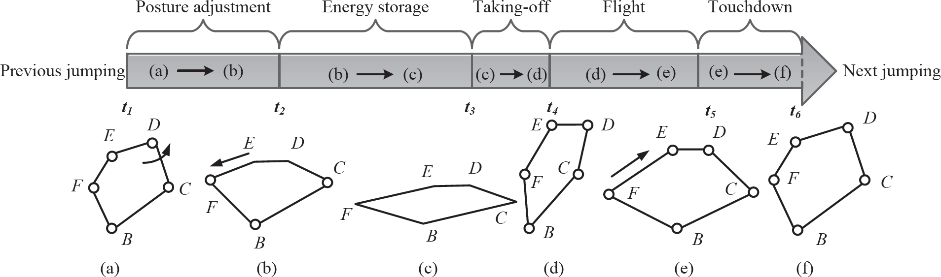
Jumping process of one cycle: “←” denotes the direction of driving rotation, “o” denotes the rotation joint
where
Similarly, we can get
During the phase of posture adjustment, the hip joint D is actuated by one motor through a geared transmission device introduced in [25]. Three constraints confine this close mechanism among which two constraints is caused by closed-loop and one constraint describes variable geared connection between link 3 and link 5. The constraints can be given by Equation (2). In Equation (2), θ
h
(0) and θ
vh
(0) are the initial hip angle and virtual hip angle respectively, which are determined by the animal's gait and can be adjusted when assembling the hopping mechanism. According to the above analysis, using Equations (1) and (2), an operator Γ
p
is used to denote the functional dependency of
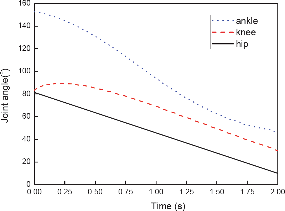
Ankle, knee and hip joints during the posture adjustment phase

Length of spring during the posture adjustment phase

In the proposed mechanism, two springs store the energy and enhance the explosive force instead of muscles. This phase mimics the contraction of muscles. Unlike the compact kick-and-bounce mobile robot in [28], this mechanism does not need high holding force to keep the energy-storing posture. Compared with the asymmetric mechanism [2, 3, 29], this mechanism has novel point that one low-power linear motor actuates the screw to adjust the length of l5. The spring hinged between joint C and joint P is elongated gradually in an alternating way via the closed-chain mechanism's transformation. In this way, the jumping mechanism obtains the nonlinear force using the linear spring during the taking-off, which is beneficial for jumping performance with regard to height in the vertical direction and distance in the horizontal direction. In this phase, the hip joint is locked by one locking mechanism, thus the angles of θ h and θ vh are constant. The positions of point C and P can be written as the function of l which can be expressed as another operator Γ e in this phase.

where rC = (xC,yC) and rp = (xP, yP) are the positions of point C and P. The force Fs and potential energy Ep in the spring are determined by the length of l and can be given by the following equation:


where ks is the stiffness of the spring and ls is the original length of the spring. The values of ks and ls are 0.6 N/mm and 120mm is used in the later simulation. Fig:6 shows the length change of spring versus the length change of link. The elongation of link 5 is about 50 mm, while the stretch elongation of the spring is 80 mm. The holding force to keep the state is achieved by the self-locking function of the screw.

Length of spring versus the length change of link 5
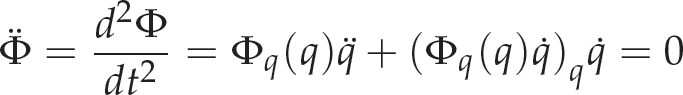
In this phase, the energy in the spring is released to mimic muscle relaxation of animals. The study during taking-off focuses on the dynamics. Modelling the contact between the ground and foot as a compliant continuous contact, which will be introduced in Section 4, the general coordinate can be simplified as qto = [xA,yA, θ1,θ2,θ3,θ4,θ5] T because the length of l keeps constant in this phase. For the cutting-open method, the Lagrange dynamic equation can be expressed as:

where D(qto) is the 7 × 7 inertial matrix,

The method of contact forces will be introduced in the Section 4 and the solution of dynamic equation can be found in the Section 5.
There is no unilateral constraint from ground in this phase. The Lagrange dynamic equation can be expressed as:

where qf = [xA, yA, θ1, θ2, θ3, θ4, θ5] T are generalized coordinates and external force Ff equals [0,0,0,0,0,0,0] T in the flight phase.
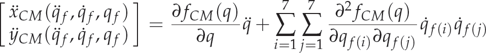
The jumping robot's absolute CoM position is specified by the Cartesian coordinates of CM(xCM, yCM) with respect to the world coordinate frame xoy. The CM of the jumping robot can be computed with respect to the world coordination.

where (xcm,i, ycm,i) indicates the position of the CoM of the ith link. Therefore the linear velocity and acceleration of the CM of jumping robot can be given by the following equation:

During the flight phase, there is no external force and additional constraints applied on the robot, thus the CM of the jumping robot evolves according to Newton's second law:

Therefore, the trajectory of the jumping robot's CM can be computed using equation

which also can be used to estimate the jumping performance.
During this sequence, impulse is generated because of the contact between the ground and the foot. The CM of the jumping robot descends and the spring is stretched allowing part of the energy to be stored. This mechanism is a compliant design in this regard. By this means the impulse force also decreases. Differing from the traditional rigid contact during the touchdown phase, we consider the influence of the environmental factors. The dynamic system has similar generalized coordinates to the phases of taking-off and flight qtd = [xA, yA, θ1, θ2, θ3, θ4, θ5] T , and the dynamic equation can be modified as:

where Ftd = [FN, FT, 0,0,0,0,0] T . In this phase, the linear motor used to change the length of link 5 rotates in the opposite direction. The energy stored in the spring from the impulse dissipation is released as the length of link 5 decreases.
Contact with the ground during the phase of taking-off and touchdown is one unilateral constraint, which generates the normal force and tangent friction force. The normal force FN and the tangential friction force FT significantly impact upon jumping performance. If the environmental characteristics, such as the shape of the substructure or the stiffness of the clay, change, the effect on jumping locomotion performance also changes.
Normal force model in the contacting process
To solve the impact problem, methods can be divided into two families: the discontinuous and the continuous approaches [30]. The rigid body assumption made here means that the foot and the ground are supposed to be hard and only very small local deformations are required to generate very large contact pressures. The discontinuous approaches assume that the impact occurs instantaneously. The displacement of the hopping robot does not change at that moment, while the velocity and momenta balances of the system change instantaneously. However, the contact force depends on the shape, conditions and material properties of the contacting surfaces, all of which suggests a more complex relation in view of real application environments. Therefore, it is a reasonable choice to adopt the continuous contact approaches [31]. Continuous contact approaches are based on regularized-force models that relate to the force and deformation of the bodies in collision, or are based on unilateral constraints techniques that avoid penetration between bodies. The best-known continuous contact method is based on Hunt and Crossley's work. The contact model consists of a spring in parallel with a nonlinear damper. The model uses the general trend of the Hertz contact law, in which a hysteresis damping function is incorporated with the intent to represent the energy dissipated during the impact. The contact force, FN , is given by equation

where
k is the equivalent stiffness of the contact model;
n is the Hertz's exponent;
δ is penetration depth;
ζ is damping constant;
assuming that the robot's foot is rigid with only very small local deformations and the ground is elastic. The position of initial contact point is [x0,y0], thus the penetration depth recognized as deformed displacement in the normal direction is δ = yA – y0, and penetration velocity is

for the case of the proposed jumping robot impacting with the ground.
When in contact with the ground, the robot's foot slides or tends to slide relative to the ground. Friction force is generated which is tangential to the surfaces of contact. For the proposed jumping robot, the friction force provides the acceleration in the horizontal direction. The Coulomb friction law of sliding friction can represent the most fundamental and simplest model of friction between dry contacting surfaces [32]. The Coulomb friction law is independent of relative tangential velocity. In practice, this is not true, because friction forces can depend on many parameters such as material properties, temperature, surfaces cleanliness, and velocity of sliding. Meanwhile, the Coulomb friction model is problematic regarding both the analysis and simulation because it is a strongly nonlinear system model. Therefore, a continuous friction force velocity relationship is desirable. On the basis of the Coulomb-Viscous friction models, another model with better numerical features is to replace the sign function in the simplified Coulomb friction model shown with a tanh function. The model called Coulomb-tanh [32] is formulated as:

where Fc is the Coulomb sliding friction force defined as Fc = μFN, in which μ is the coefficient of friction and FN is the normal force in the contact. kf is a coefficient that determines how fast the tanh function changes from near −1 to near +1. Combined with the normal force in Equation (16), the tangential friction force can be expressed as:

Computational method and simulation of dynamics equation
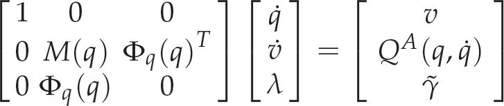
In the phases of standing, taking-off, flight and touchdown, the dynamics equations can be written the unified formula as:
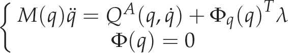
where q = qto = qf = qtd,

Equations (20) and (21) must be satisfied in any valid numerical method of solution for the equations of motion. Using the general differentiation index reduction method, we replace Equation (19) with the following equation:

where
Baumgarte's stabilization [33] is probably the most widely known and used scheme for practical engineering applications because it is simple to implement and understand. It replaces the holonomic constraint (2) by a linear combination of the constraint and its time derivates in such a way that the differential equations for the constraints are stable. To damp out these violations, Baumgarte proposed using

instead of Equation (21). Larger positive values in α and β parameters can ensure
where
According to the flow chart in Figure 7 and general index-1 DAEs derived using the above method, the simulation results about jumping performance under the influence of gear ratio i, the equivalent stiffness and friction coefficient in the foot-terrain contact model are shown in Figure 8, 9 and 10 respectively. The numerical simulation results show that both the equivalent stiffness and friction coefficients have an obvious influence, including on the jumping height and distance. The bigger the friction coefficient, the better the jumping performance both in relation to height and distance. As the equivalent stiffness increases, so the jumping height increases, however, there is evidential trend regarding the jumping distance.

The computation procedure flow chart
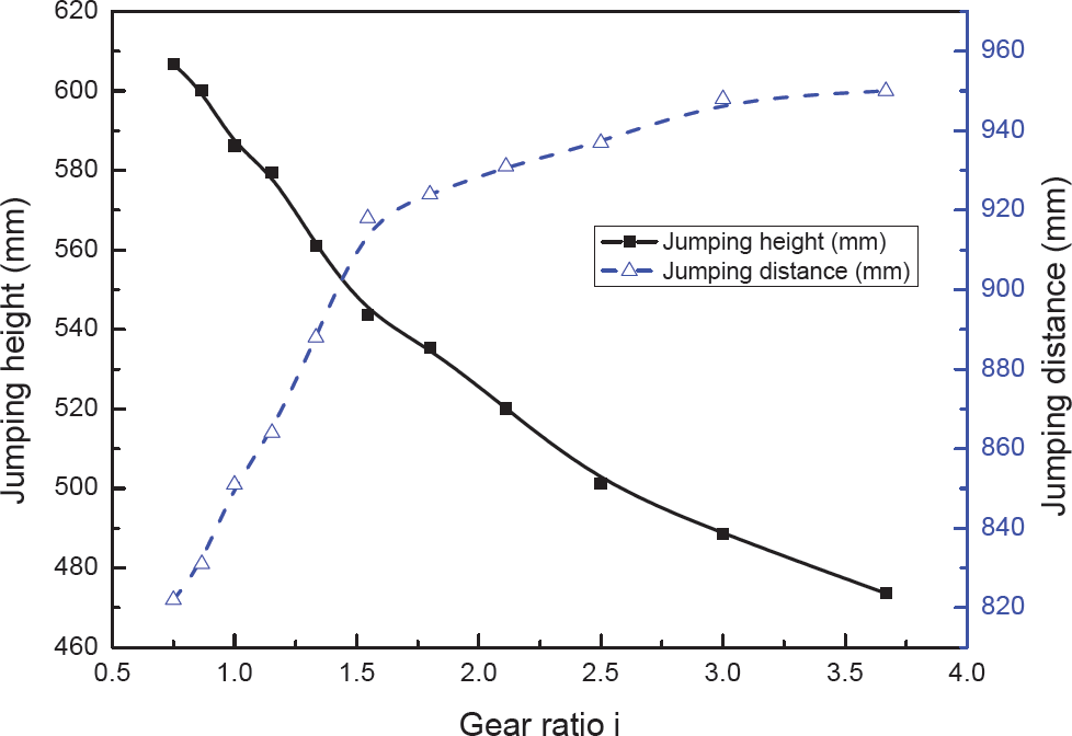
The changes of jumping performance by adjusting the gear ratio i

The changes of jumping performance under the influence of equivalent stiffness

The changes of jumping performance under the influence of friction coefficient
Simulation parameters

One primary prototype was constructed as shown in Figure 1(b). In order to see the difference between each jump clearly, a graduated scale was marked in the background setting. Jumping motion is shown in Figure 11 from right to left, with the images taken at 25Hz with a high speed camera, so the jumping distance and jumping height can be measured by captured pictures. Figure 12 compares the simulation results using the above method and experimental results. The jumping height represents vertical maximum height from robot foot to the ground while the the jumping distance represents the horizontal distance of toe tip point between taking off and landing. The graphic of Figure 12 clearly indicates that the distance of jumping in the horizontal direction increases with the increasing gear ratio, while the height of jumping decreases in reverse. The jumping robot can enhance the capability to adapt to unknown cluttered environments, such as those present in research and rescue environments, by using this strategy.

Sequential photos of jumping experiment with transmission i = 1
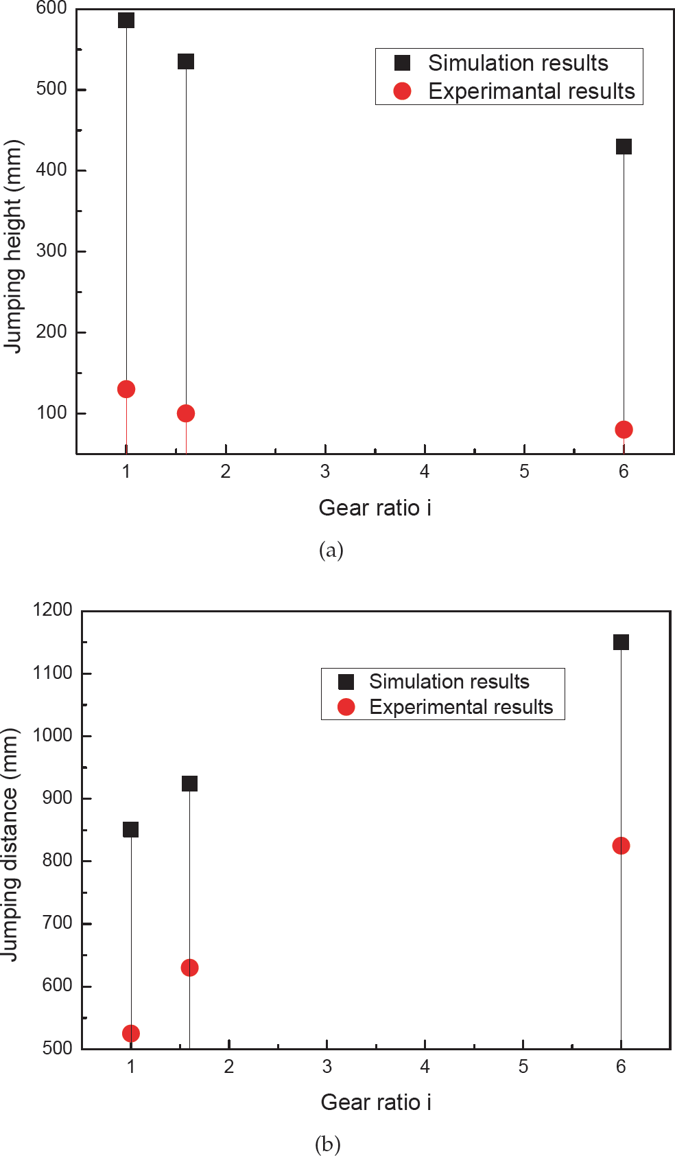
Comparison of simulation and experimental results under different transmission ratios (a) jumping height (b) jumping distance
Through jumping locomotion, legged animals show their dexterity and mobility to jump over obstacles and move in rough terrain. In order to move in the unknown terrains, jumping locomotion has the capability of obstacle navigation. Here, a bio-inspired jumping robot revealing biological characteristics is proposed. Meanwhile, the kinematics and dynamics of the simplified model of the jumping mechanism, and one cycle sequence are introduced from the point of view of a biological jumping locomotion. Moreover, a compliant contact model with nonlinear damping is investigated looking at the influence of various ground environments on the jumping performance. The numerical simulation results show that both equivalent stiffness and friction coefficient have an obvious influence, including on jumping height and distance. The bigger the friction coefficient, the better the jumping performance both in terms of in height and distance. As thee quivalent stiffness increases, so the jumping height increases, however, there is evidential trend to the jumping distance. Both the experiments and simulations indicate that the jumping distance in the horizontal direction increases with the increasing gear ratio, while the jumping height decreases in reverse. The jumping robot can enhance the capability to adapt to unknown cluttered environments, such as those found in research and rescue environments, by changing gear ratio i.
The fact is that terrain parameters are difficult to directly measure. The estimation methodology of terrain parameters should be focused on foot-terrain interaction. The purpose of this work is to allow the jumping robot to improve mobility in high-risk, rough terrain environments, through the development of the jumping locomotion and motion planning.
Acknowledgements
This work was financially supported by National High Technology Research and Development Program of China (grant no. 2007AA04Z207), the National Natural Science Foundation of China (grant no.50975230), the Graduate Starting Seed Fund of Northwestern Polytechnical University under grant no. Z2012057, and the Doctoral Scientific Fund Project of the Ministry of Education of China under grant no. 20136102130001.