
Abstract
A small, bio-inspired and minimally actuated intermittent hopping robot for planetary surface exploration is proposed in this paper. The robot uses a combined-geared six-bar linkage/spring mechanism, which has a possible rich trajectory and metamorphic characteristics and, due to this, the robot is able to recharge, lock/release and jump by using just a micro-power motor as the actuator. Since the robotic system has a closed-chain structure and employs underactuated redundant motion, the constrained multi-body dynamics are derived with time-varying driving parameters and ground unilateral constraint both taken into consideration. In addition, the established dynamics equations, mixed of higher order differential and algebraic expressions, are solved by the immediate integration algorithm. A prototype is implemented and experiments are carried out. The results show that the robot, using a micro-power motor as the actuator and solar cells as the power supply, can achieve a biomimetic multi-body hopping stance and a nonlinearly increasing driving force. Typically, the robot can jump a horizontal distance of about 1 m and a vertical height of about 0.3 m, with its trunk and foot moving stably during takeoff. In addition, the computational and experimental results are consistent as regards the hopping performance of the robot, which suggests that the proposed dynamics model and its solution have general applicability to motion prediction and the performance analysis of intermittent hopping robots.
1. Introduction
Currently, there is an increasing interest in research into hopping robots for planetary surface exploration. Due to its better mobility in unknown, rugged terrains and low/micro-gravity environments, hopping robots can overcome the drawbacks of wheeled rovers, such as limitations on flexibility of locomotion, ability to traverse, and miniaturization, etc. [1-6]. However, as the hopping period is extremely short and the hopping motion needs to be actuated by an instantaneous explosive force, hopping robots which are mechanically equipped with a multi-DOF structure and multi-actuators are unlikely to be implemented due to difficulties involving its control and its multi-actuators [7]. As such, the exploration of an efficient hopping mechanism and driving mode for the implementation of small, solar-powered, minimally-actuated, intermittent and bio-inspired hopping robots, based on the physical structure and locomotion of jumping animals, becomes the focus in the field [8-19].
To date, the representative hopping robots employed for planetary mobility consist of the three generations of robots presented in [9-11]. The first generation is a spherical robot whose hopping motion is generated by the release of a spring after it is compressed via a power screw. The second generation is a “frog” robot. The third generation is a wheeled hopper based on the second robot. The second and third generations are equipped with a symmetrical, geared, six-bar mechanism. They can transfer a linearly decreasing force of the springs into a nonlinearly increasing driving force which can overcome the inefficient hopping of the first generation. However, they are still simple catapult mechanisms that can only catapult along one direction, with a single and unstable hopping stance. Because of this, their bodies always hit the ground sharply when landing. Motivated by the force characteristics of closed-chain mechanisms, various kinds of hopping mechanisms are proposed, such as a geared four-bar mechanism [12,14] and a geared five-bar mechanism [14-19], etc. However, most of these are also catapult mechanisms with a symmetrical structure.
The hopping performances of intermittent hopping robots depend upon the dynamics characteristics of the hopping process, which involves takeoff, flight and landing. Since intermittent hopping robots can jump, upright themselves after landing and then jump again, without the need for the real-time identification of environments and complex dynamic control [8-16], its hopping performance mainly depends on the dynamics of takeoff. However, most of the earlier works consist of a static analysis of the hopping mechanisms' driving characteristics, which ignores the masses of linkages [9-19] or else dynamics analysis by simplifying the hopping mechanisms as nonlinear spring-mass models [17-19]. These simplified dynamics models and their analysis have not yet involved consideration of multi-body dynamics, which are unable to reveal the practical hopping characteristics of combined spring/linkages hopping mechanisms, such that they are inapplicable to the motion prediction and performance analysis of intermittent hopping robots.
As discussed above, in order to explore a small, intermittent hopping robot that is solar-powered, minimally actuated and has biomimetic hopping characteristics – such as a nonlinearly explosive driving force and a stable hopping stance – another paradigm (as shown in Figure 1) is proposed in this paper. The robot uses a combined-geared six-bar linkage/spring metamorphic mechanism as a hopping mechanism so as to imitate the open-chain physical structure of a kangaroo. By utilizing the achievable rich trajectory and metamorphic characteristics of the hopping mechanism, the robot is able to recharge, lock/release and jump by using a single micro-power motor as the actuator.

Mechanism model of the bio-inspired hopping robot
Because the robot is a robotic system with a closed-chain structure and an underactuated redundant motion, the constrained multi-body dynamics model is derived by taking the time-varying driving parameters and the unilateral constraint, etc., into consideration. Next, the established dynamics model – which consists of Euler-Lagrange equations mixed with higher order differential and algebraic expressions – is solved by the immediate integration algorithm. Finally, a computational simulation and prototype experiments are conducted.
2. Mechanism Model of the Hopping Robot
2.1 Mechanism of the proposed robot
The intermittent hopping robot presented in this paper is bio-inspired by a typical hopping animal – the kangaroo – which is characterized by a bipedal but synchronous (similar to a single leg) hopping motion along the sagittal plane of its body. The kangaroo's physical structure consists of a trunk, thighs, shanks, feet, muscles and tendons, which together constitute a rigid-flexible coupling system [20]. Kangaroo-inspired robots are commonly based on open-chain linkages and a number of actuators, with the obvious risks to system reliability. Hence, in order to explore a minimally actuated kangaroo-inspired hopping robot with a compact structure, we propose an intermittent hopping robot, as shown in Figure 1.
By referring to the movement of the kangaroo, the proposed robot is bipedal with a synchronous hopping motion. The mechanism of the robot is based on a geared six-bar parallel mechanism that lies in the sagittal plane of its movement.
As shown in Figure 2, each of bars 2, 3, 5 and 6 is linked with an incomplete gear fixed on one end. By referring to the physical structure of the kangaroo, bars 1, 2, 3 and 4 represent the foot, shank, thigh and trunk, respectively, and the lengths of these bars are in proportion to the physical dimensions of a kangaroo. Bars 5 and 6 are the enclosed bars of the geared six-bar mechanism. Accordingly, joints A, B and C represent ankles, knees and the hips, respectively. Since geared linkages can achieve rich motion trajectories, it is feasible that a robot with a 1-DOF closed-chain mechanism can realize a biomimetic multi-DOF hopping stance by selecting the applicable parameters.
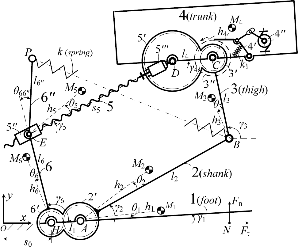
Schematic diagram of the proposed hopping robot
Springs are used as the energy storage/release component of the robot. In order to increase the energy storage capacity of the springs, bar 6 is extended to bar 6″ and the two ends of the springs are installed on joint B and point P of the extension bar 6″. The advantages of the manner of the springs' installation were presented in our previous work [21].
2.2 Principle hopping process of the proposed robot
The reliability and efficiency of the energy recharge/release mechanism are important as contributing factors to the performance of intermittent hopping mechanisms. In [9-11], robots are recharged by a power screw after the screw connects with a latch mechanism on the bottom of the six-bar linkages. As the recharge completes, the screw extends out over the robots' body, which makes them less amenable to miniaturization due to the protection cover of the screw. In [17-19], the robots are compressed (along with the recharge of the springs) by a rope drive system, which is inefficient (having the need for a large driving torque for the reel).
To overcome the shortcomings of these pervious works as regards their incompact structure and inefficiency, we here propose a novel mechanism for the recharge/release of energy which is based on the fundamentals of a metamorphic mechanism [22–23]. As shown in Figure 2, the length of bar 5 is adjustable by using the power screw driven by motor 5″′. Motor 5″′ is fixed to gear 5′. The ratchet and pawl mechanism 4′ is the locking/release mechanism of the robot. When the ratchet mates with the pawl by the action of spring k1, the geared six-bar linkages can only be compressed – only the pawl is tripped by motor 4″ and the robot is released to jump. The robot achieves the recharge/release of the springs in stages by transforming its topological structure, by the following steps:
When the robot is ready for recharge after the previous hopping process is completed, nut 5″ moves towards motor 5″′ via the reverse rotation of the power screw driven by motor 5″′. Along with the movement of the nut, the springs are shortened, whereupon the spring force decreases. In this state, a rope drive system (omitted in Figure 2), driven by the movement of the nut, pulls bar 3 to rotate counter-clockwise. Accordingly, the angle between bar 3 and bar 5 becomes larger due to the gear transmission (3′ and 5′). When the angle between bar 3 and bar 5 reaches a given value, motor 5″′ stops running. As step (1) is completed, nut 5″ moves in the opposite direction via the positive rotation of the power screw driven by motor 5″′. Since the relative positions between bars 3, 4 and 5 are locked by the ratchet and pawl mechanism 4′, the lengths of bar 5 and the springs increase along with the movement of nut 5″. When the lengths of bar 5 and the springs reach given values, the recharge of the springs is completed. When the robot is ready to jump, the pawl is tripped by motor 4″, whereupon the springs are released and takeoff commences. The follow-up is the flying and landing process. The steps presented above will repeat, if the robot needs, for the next operation cycle.
If we take bar 1 as the frame of reference, in step (1) the topological structure of the robot is 6R-1P-2G with 2-DOF, where R, P and G represent the revolute joint, the prismatic pair and the gear pair, respectively. In step (2), the robot is changed to 4R-1P-1G with 1-DOF. When the recharge of the springs is completed, the robot becomes 4R-1G with 0-DOF, until the takeoff commences. When the robot begins to takeoff, the robot is changed into 6R-2G with 1-DOF until landing. After landing, and since the robot is ready to be recharged for the next jump, it becomes 6R-1P-2G with 2-DOF. Accordingly, it can be seen that the structure and DOF of the robot differ at different stages of the operation process, which constitutes the characteristics of a metamorphic mechanism [22–23]. By utilizing metamorphic characteristics, the robot can achieve an adjustment of attitude, the recharge/release of the springs and takeoff by using a single micro-power motor as its actuator.
3. Dynamics Modelling of the Hopping Robot
3.1 Analysis of the dynamics model
As shown in Figure 2, the ground is taken as the frame of reference to establish the fixed-coordinate system for the robotic system, where the point O on the ground is selected as original point, the x-axis represents the horizontal coordinate and the z-axis is perpendicular to the surface of the paper. Let s0 represent the length between point O and joint H, and γ1, γ2, …, γ6 represent the angles between the x-axis and bar i (i = 1, 2, …, 6) respectively.
According to the above analysis of the structure and the operation cycle of the robot, it can be seen that the robot has the following characteristics during takeoff:
The robot is a multi-body system; however, it is constructed as a 6R-2G closed-chain mechanism with 1-DOF. Accordingly, only 1 variable among γ2, γ3, γ4, γ5 and γ6 is independent. The others – being related with the independent variable – are determined by the constraints of the structure and motion.
The robot's hopping motion is generated by the forces of the springs. Meanwhile, the forces of the springs are determined by the motion parameters of the robot. It demonstrates that the robot has the characteristics of time-varying driving parameters, namely the coefficient matrices of the robotic dynamics model will be non-constant.
The contact between the robot and the ground during takeoff is a unilateral constraint where sliding and tilting may occur. Hence, the robot has 3-DOF of motion even though only 1-DOF constitutes its mechanical structure. This shows that the robot has redundant motion and that the sliding and tilting are underactuated.
In order to make the robotic system analysable, we replace the ground unilateral constraint with constraining forces and treat them as active forces, where the sliding displacement and tilting angle of bar 1 represent the movement caused by the constraining forces. Since the robot's takeoff inherently occurs along with the transformation from the elastic energy of the springs into the gravitational potential energy and kinetic energy of the robot, the dynamics modelling presented in this paper is based on the transformation process of the energy. As shown in Figure 2, the sliding displacement and tilting angle of bar 1 can be represented by s0 and γ1, respectively. There are only 3 variables among γ1, γ2, …, γ6 and s0 which are independent. If the 3 independent variables are defined as the generalized coordinates, the positions of the joints and the bars' centre of mass (COM) will be difficult to express by the generalized coordinates. Hence,
3.2 Dynamics equations
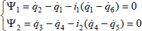
As discussed above, the generalized coordinates q1, q2, …, q6 are related with each other by the geometric relationship of the closed-chain and the transmission ratio of the gear pairs. As shown in Figure 2, the geometric relationship of the closed-chain can be expressed by the relationship between the vectors, as follows:

By transforming Equation (1) into an algebraic expression, it can be rewritten as:

where li represents lengths of bar i, l1 = lHA, l4 = lDC, and C() ≜ cos(), S() ≜ sin().
Likewise, by defining i1 as the gear ratio of the gear pair (2′ and 6′) and i2 as the gear ratio of the gear pair (3′ and 5′), the transmission ratio of the gear pairs can be expressed by:
To allow the dependent generalized coordinates to be treated as independent variables, based on Lagrange's equations of the second kind, the dynamics model of the robotic system can be obtained by using the undetermined multipliers of the constraints (namely the Lagrange multipliers) λi (i = 1, 2) and ρi (i = 1, 2), as follows:
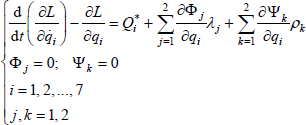
where L is a Lagrangian function and Q*i is the generalized active force corresponding with qi.
3.3 L and Q*
3.3.1 Lagrangian function L
As shown in Figure 1, each component part of the robot – bar i (i = 1, 2, …, 6) – is of irregular shape, whereby the COM of bar i is not located at the geometrical centre. The typical methods for robotic dynamics are generally based on the assumption that the COM of linkage is located at the geometrical centre. However, if the lumped mass method is used in dynamics modelling, the difference for the COM's position between the dynamics model and the actual component parts will affect the calculated results of the dynamics model. Hence, and without loss of generality, we assume that the COM of bar i (i = 1, 2, …, 6) can be located at an arbitrary position, where hi represents the length between Mi and the corresponding joint below, and θi represents the deflected angle between Mi and bar i, as shown in Figure 2. Accordingly, the position vectors of bar i can be expressed by:

By taking one derivative of Equation (5) and [q1, q2, q3, q4, q5, q6]T, the translational velocity and the angular velocity of the bars can be obtained. Accordingly, the summation of the kinetic energy of the bars – namely, the total kinetic energy of the robotic system – can be expressed by:

where mi and Ii, respectively, represent the mass and the rotational inertia of bar i.
The potential forces acting on the robotic system include the tension force of spring

where k and l0, respectively, represent the stiffness coefficient and the initial length of spring, g represents the acceleration of the gravity, θ66″ represents the included angle between bar 6 and bar 6″, l6″ represents the length of bar 6″, and rB and rP represent the position vectors of joint B and joint P, such that:

By combining Equation (6) with Equation (7), the Lagrangian function L can be obtained by:

3.3.2 Generalized active forces Q*
The forces acting on the robot during takeoff consist of gravity


where –m(r̈Mi + g) represents the inertia force acting on bar i,
According to the principle of virtual work, Q* can be expressed by:

where δ
Since
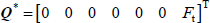
Let the acting point of

If s1 > 0, bar 1 (the foot of the hopping robot) will keep contact with the ground – i.e., q1 can be treated as a constant q1 = 0. Only if s1 = 0, bar 1 can tilt up around joint H – i.e., q1 has to be treated as a variable and q1 > 0 due to the unilateral constraint. Hence, whether sliding or tilting occurs during takeoff depends upon q7 and s1.
4. Computation for the Dynamics Equations
4.1 Computational method
By transforming Equation (4) into a matrix expression, the dynamics equations of the robot can be expressed by:

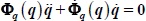
where Φ q and Ψ q are the Jacobian matrices of Φ=[Φ1, Φ2]T and Ψ=[Ψ1, Ψ2]T, respectively, and:

Equation (4) overcomes the problem of constraints by using the Lagrange multipliers; however, it follows that the Euler-Lagrange equations become a mixture of higher-order differential and algebra expressions. The solution methods for these kinds of equations can be classified as the dimension reduction method and the dimension augmentation method [24-26]. Since the former has certain deficiencies (such as poor computational efficiency) the latter – specifically, the immediate integration algorithm – is selected in this paper.
Equation (4) contains 7 dynamics equations and 11 variables, and so it requires extended differential equations. By taking two derivatives of Equation (2), the expression of closed-chain constraints can be obtained as:
Likewise, by taking one of the derivatives of Equation (3), the expression of transmission constraints can be obtained as:

By combining Equation (14) with (15) and (16), the dynamics model of the robotic system can be expressed by:

By defining the variables as follows:

Equation (17) can be expressed by:

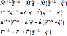
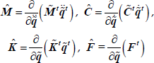
where the equivalent mass matrix
Let the variables


where:

Based on Taylor's series expansion,
where:
By combining Equation (20) with (21) and (22), the following expression can be obtained:

Similar to the linear Newmark-β method (an immediate integration algorithm), the increment of velocity and acceleration can be expressed by:

where α and β are the coefficients for the Newmark-β method, whereby generally α = 0.5 and β = 0.25.
By fitting Equation (24) into (23), the increment of displacement can be expressed by:

where:

By plugging Equation (24) and (25) into (21),
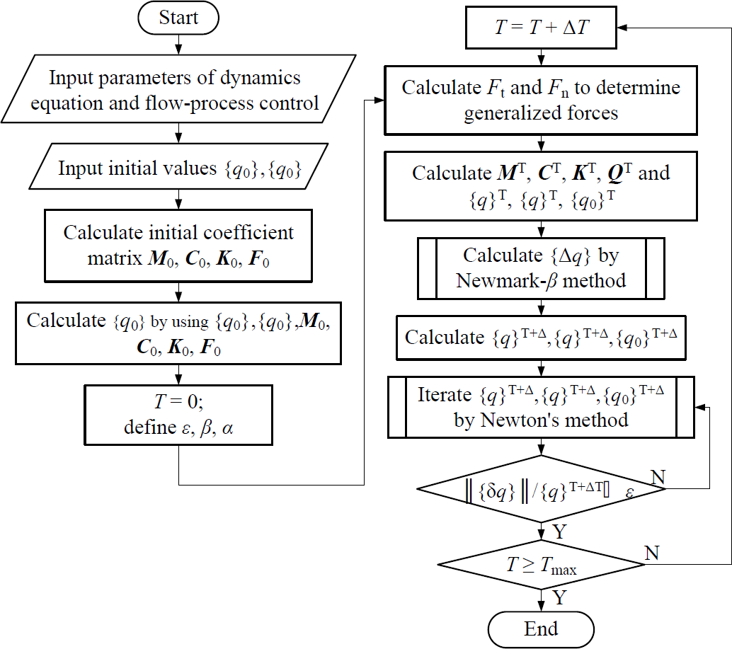
Computational procedure for the dynamics equations
4.2 Computational results
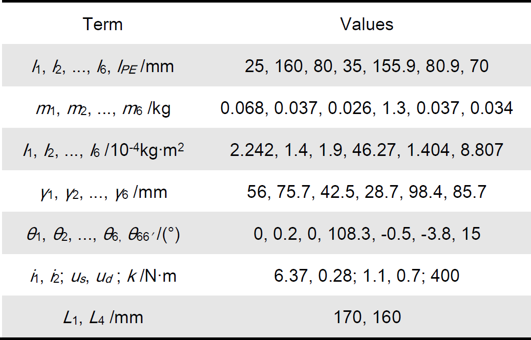
Table 1 lists the structural parameters of the hopping robot, in which L1 and L4 represent, respectively, the total length of bar 1 (foot) and bar 4 (trunk). According to our earlier prototypes' experimental results, sliding is hard to avoid. As such, us and ud are here selected as relatively large values – i.e., 1.1 and 0.7 respectively.
Structural parameters of the hopping robot
The computation for Equation (17) is implemented by using the structural parameters listed in Table 1 and the various computational conditions, such as initial displacement
Figure 4 shows the hopping stance of the robot by using the data from the computational results. Along with the release of the springs, the robot stretches out gradually, beginning with a crouching stance where bar 4 (trunk) moves in a manner of approximate translational motion. Given that the moving stance of bar 3 (thigh) and bar 2 (shank) are in accordance with the moving stance of the kangaroos' leg [20], this indicates that the robot has a 1-DOF closed-chain structure during takeoff; however, it can imitate the hopping stance of the multi-DOF open-chain system. The sub-graph in Figure 4 details the joint H's stance during takeoff, where it can be seen that bar 1 (foot) experiences obvious sliding and tilting near the end of takeoff.

Hopping stance of the robot based on the computational results
The robot's hopping motions are generated by the release of the springs. However, the ground reacting force
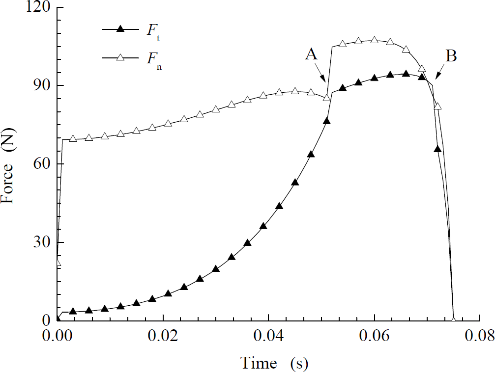
Ground reacting force
As shown in Figure 5, it can be seen that Ft and Fn are low at the onset and subsequently increase smoothly until the final part of the takeoff phase. Meanwhile, the spring force reaches its maximum at the onset and then decreases linearly. The nonlinear characteristics of Ft and Fn are consistent with the testing curves of the ground supporting forces acting on a kangaroos' foot during takeoff [20]. This indicates that the robot has biomimetic capabilities that can convert the linear spring forces into nonlinear driving forces. In addition, since the peak value of the driving force is reduced, the rated torque of the actuator is reduced as compared with the spring driving directly. This indicates that the energy storage of the robot can be recharged using a smaller power actuator.
In Figure 5, Ft is lower than Fn at the onset, though it increases rapidly. Near the end of takeoff (around point B), Ft is higher than Fn and then steeply declines. This shows that Ft reaches critical status and follows this by turning into a sliding friction force from a static friction force. In addition, it can be seen that the curves of both Ft and Fn reflect an abrupt change at point A. As with the comparison between s1 and q1, shown in Figure 6, s1 gradually decreases from 0.087 m to 0 – i.e.,

Comparison between s1 and q1 during takeoff

Variation of s0 during takeoff
In order to quantize the effect of us and ud on sliding – by supposing that us is specified as a set of given values and that ud is a continuous variable of less than us – the sliding displacement corresponding to the optional combination of us and ud can be calculated, as shown in Figure 8. It is obvious that the effect of us on sliding is greater than that of ud. If max (Δs0) ≤ 4 mm is assumed as a reasonable range for such sliding displacement, us should be given by us ≥ 1. This indicates that the loss of mechanical energy may occur if the anti-slip measures are not effective enough.

Effect of us and ud on sliding, where the maximum variation of s0 represents the sliding displacement during takeoff
5. Experimental Results
According to the theoretical model shown in Figure 1, 2 and the structural parameters listed in Table 1, the prototype of the hopping robot is implemented as shown in Figure 9.

Prototype of the proposed hopping robot
To make the prototype reliable, compact and lightweight, the mechanical parts use aircraft aluminium as their material, and each of the parts is integrally machined by CNC. For anti-slippage, the sole of the prototype is designed as a rough surface. The prototype weighs 1.3 kg and is equipped with a MultiFLEX™2-AVR as the controller, ProMotion CDS5500 robotic servo motors (each motor weighing 60 g) as the actuators, combined ultra-thin monocrystalline silicon solar cells and lithium polymer batteries as the power-supply system. The prototype is also equipped with a wireless vision system, wireless remote control devices, a self-righting mechanism and a steering (the act of pointing the prototype in the desired direction before takeoff) mechanism. It is able to independently jump, upright itself after landing and jump again. It is also able to wirelessly transmit real-time video of it environment to the main computer for artificial path-planning, such that it can steer towards the intended direction before takeoff by manual remote control.
The hopping experiments are carried out in an indoor environment. The prototype typically jumps a horizontal distance of about 1 m and a vertical height about 0.3 m, which demonstrates that the robot could potentially jump over obstacles of 4~6 times its body length. On a planetary surface – such as a lunar surface – the robot could overcome obstacles of up to 1.8 m high and 6 m long. During the experiments, the prototype's hopping stance was filmed by the high speed camera system MotionBLITZ Cube, at 120 frames per second. The video snapshots are shown in Figure 10. The hopping stance of the prototype is in accordance with the computational results shown in Figure 4. Given that the foot tilts up when the prototype is about to leave the ground, this proves that such dynamics modelling as takes tilting into consideration is feasible.
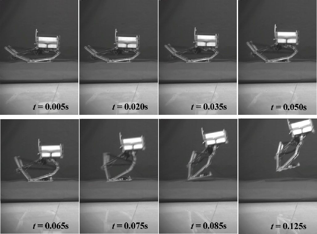
Takeoff stance of the prototype, where timing starts as soon as the springs begin to release
By using a high speed video motion analysis system, the rotation angle of the parts of the prototype can be measured. The velocity and acceleration of the parts can then be obtained by numerical fitting and differentiating the rotation angle data. Figure 11 presents the comparison between the computational and experimental velocity of the COM of the trunk (bar 4). The curve of the computational velocity is consistent with the experimental results, which verifies the availability of the dynamics modelling and its computation. Although the computational values are larger than the experimental values, the takeoff period of the computational results is shorter. This is because the dynamics modelling is based on the lumped mass model and do not involve the friction of the joints or the damping of the springs and the ground.

Velocity of the COM of the trunk (bar 4) during takeoff
Figure 12 shows the computational and experimental acceleration of the COM of the trunk. The convex profile of the acceleration curves demonstrates that the hopping robot can transform the linear force of the springs into the nonlinear driving force of the hopping motions.

Acceleration of the COM of the trunk (bar 4) during takeoff
In addition, the sliding distance of the prototype's foot as measured in the experiments is about 3 mm. According to the paradigms shown in Figure 8, this indicates that the anti-slippage for the sole of the prototype is effective. As shown in Figure 10, the trunk of the prototype moves forwards and upwards in a manner of near-translational motion during takeoff. This will be helpful for the robot in enabling it to fly and touchdown stably so that it could take pictures during the flight phase and protect any internal instruments while landing.
6. Conclusions
A small and bio-inspired intermittent hopping robot equipped with a combined-geared six-bar linkage/spring metamorphic mechanism is proposed. The results of the theoretical analysis and the prototype experiments show that the robot – using a micro-power motor as the actuator and solar cells as the power supplies – can achieve a biomimetic multi-body hopping stance and a nonlinearly increasing driving force. Typically, the robot can jump a horizontal distance of about 1 m and a vertical height about 0.3 m, and its trunk and foot move stably during takeoff. This indicates that the robot is useful for tasks in unknown, rugged terrains and that it is especially suitable for planetary surface exploration in small gravity environments.
A constrained multi-body dynamics for the takeoff process of the robot is derived. This involves the dynamics characteristics of a closed-chain structure, time-varying driving parameters and ground unilateral constraint. The computational and experimental results indicate that the proposed dynamics model and its solution methods are available and have general applicability to the motion prediction and performance analysis of intermittent hopping robots.
In addition, both the theoretical analysis and prototype experimental results show that sliding and tilting may occur during takeoff because of the ground unilateral constraint. This indicates that mechanical energy loss may occur during takeoff if the anti-sliding measures are not effective enough.
Footnotes
7. Acknowledgments
This research is supported by the National High-tech Research and Development Programme of China (863 Project, Grant No. 2007AA04Z207) and the National Natural Science Foundation of China (Grant No. 50975230).