
Abstract
Jumping may be considered to be quite a useful means of mobile robot locomotion, but acquiring a stable landing has been a difficult problem. This paper reports on the design, analysis, simulation and experiments of a mesoscale jumping robot that is capable of stable landing. A jumping mechanism inspired by jumping insects is introduced and an actuation scheme using only one shape memory alloy (SMA) spring is described. Experimental results show that a robot with a 17 gram weight and 13 cm diameter can jump forward as far as 1.2 times its body diameter and vertically as high as 1.5 times its body diameter. In addition, the robot is able to land in a stable manner and recover its initial posture after landing.
1. Introduction
Compared to wheeled robots, legged robots have advantages in terms of the ability to overcome obstacles. While wheeled robots may not run over a step that is higher than the robot's wheel radius [1], walking robots can overcome an obstacle whose height is up to the maximum ground clearance [2]. In this regard, jumping can be considered as the most prominent locomotion means on the ground [3]. Some robots are reported to be able to jump as much as ten times their body height [4, 5]. Besides, jumping locomotion can be advantageous for travelling speed and energy efficiency [3].
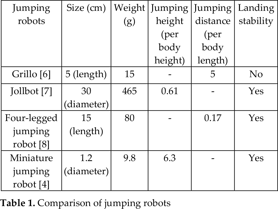
In spite of its merits, jumping has not been extensively employed for mobile robots. One of the significant problems is the ability of achieving a stable landing. It has been found that even natural expert jumpers like grasshoppers and froghoppers sometimes fall on their backs [6]. As summarized in Table 1, it is quite a difficult problem to achieve the ability to make a stable landing as well as outstanding jumping performance in terms of jumping height and distance. One might notice, in Table 1, that Grillo [6] possesses the best jumping distance, but it does not have stability on landing. Meanwhile Jollbot [7] and a four-legged jumping robot [8] can recover their stable posture after landing, but its jumping ability is relatively poor. A miniature jumping robot [4] that has a spherical shape shows promising results in both jumping performance and the landing stability.
In order to achieve stability in landing as well as good jumping ability for a mesoscale robot, we first study and employ the jumping principles of insects. In particular, the froghopper's jumping mechanism is of interest to us. We also use a spring-type shape memory alloy (SMA) instead of conventional actuators, which is mainly for reducing weight. Electromagnetic motors, for example, are available across a large range of sizes and weights, but the power-to-weight ratio is not so large [9]. Additional components like a power amplifier and a motion converter may be needed too. The idea of using an SMA actuator for a jumping robot was introduced in our previous four-legged jumping robot [8]. However its jumping performance and efficiency are unsatisfactory and the structure is complicated. We present in this work a new jumping robot to overcome this weakness.
Comparison of jumping robots
2. Design of the robot
The robot is designed to consist of two modules: the body module and the leg module, which together are equivalent to a jumping mechanism and a landing mechanism, respectively. The body module includes a robot body on which a crank and an SMA spring are installed. A control board and a battery are also attached to the robot body. The leg module consists of a leg rod with a hook, a base, and a spherical frame. All of the parts are connected to each other by rigid joints. The leg can slide relative to the body module, and the modules are connected by a conventional expansion spring. The body module is designed to be much heavier than the leg one. This guarantees that the robot can obtain the largest jumping distance [3].
2.1. Design of the jumping mechanism
The design of a jumping mechanism is the most decisive component in the jumping robot's design. We take a bio-inspired design approach for designing an energy storage system and an energy release system. Burrows and his colleagues reported that the froghopper can obtain a jumping height of 700 mm, i.e., about 100 times its body length [10]. Analysis of the structure of the froghopper reveals that the energy generated by the trochanter muscle is stored in the strengthened thoracic cuticle which may contain resilin [11].
The jumping mechanism of the froghopper can be modelled as the one composed of an actuator, an energy storage system and a one-way latch. The mechanism is designed to work such that the energy generated by the actuator can be stored gradually in the energy storage system and released quickly by the action of the latch. Fig. 1 shows the two-dimensional (2D) structure of the froghopper's rear legs, as seen from the bottom. Fig. 1(b) displays the latch mechanism on the froghopper when preparing for jumping. In doing so, the leg is rotated and the coxal protrusion acts as a latch to lock the femur of the leg. This process is for storing energy. A similar jumping mechanism is also found in other outstanding jumpers, such as the flea. We adopt this working principle, but apply it to robot design in a simplified way: the minimization of the degree of freedom (DOF) of the jumping mechanism to one. We select a spring-type shape memory alloy (SMA spring) as the only actuator for the robot. A 2D model of the jumping mechanism is shown in Fig. 2.
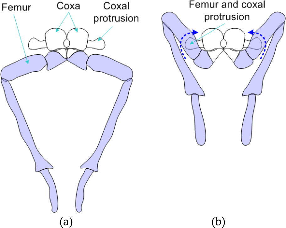
Structure of the froghopper's rear legs: (a) In the free state, (b) In preparation for jumping (adapted from [11])

Two-dimensional model of the jumping mechanism
Properties of SMA spring

The SMA spring is made of one-way nickel-titanium SMA. The weight of the SMA spring is about 1 gram. Table 2 summarizes the properties of the SMA spring that are obtained from experiments with a load of 800 gram. It shows that the length can change from 60 mm to 29 mm in 0.7 sec when an electric voltage of 12 VDC is applied. This means that the spring can carry a load 800 times as heavy as its own weight, and the displacement is equal to its length. Therefore, the SMA spring would be quite suitable for a jumping mechanism that requires a large amount of energy for taking off. In addition, the displacement is in a straight line, and so it can be transferred directly to the energy storage system.
The SMA spring also has disadvantages in terms of power consumption and response time. We found from experiments that quite a large amount of heat remains in the SMA spring after a full contraction. The remaining heat not only reduces efficiency but also causes the slow release of the actuator. In order to solve this problem, we suggest using a pulse width modulation (PWM) signal as well as the low voltage supply source. Although this method may lengthen the contraction time, it can reduce the remaining heat and shorten the cooling process as a result. One can see from Table 2 that when 12 VDC is used, the contraction time is about 2.3 seconds shorter than that for the case where the PWM method is applied. However, the release time in the first case is 5 seconds longer compared to that of the second case. Therefore, the total time can be reduced if the PWM signal is utilized.
As for the energy release system of the jumping mechanism, we also adopt the working principle of froghoppers. When the insect prepares for jumping, the coxal protrusion acts as a latch which maintains the femoral protrusion. The latch is quickly unlocked when the froghopper performs a jump and the stored energy is immediately released [11]. In the robot design, the hook component in Fig. 2 plays the same role as the one-way latch. The SMA spring has quite a slow response when it is relaxed. The use of hook is the key solution to overcoming the slow response problem.
One cycle of a jumping action can be divided into three phases: preparation, jumping and recovery. In the preparation phase, the SMA spring is activated by the application of electric voltage. In Fig. 3(a), the contraction force F s of the SMA spring rotates the crank clockwise around its centre. Since the crank is in contact with the hook of the leg, the crank pulls the hook upwards relative to the body base. As a result of the motion of the hook, the expansion spring is extended and the elastic force F k is formed. The elastic force of the spring acts on the hook in the opposite direction as the crank force. However, this force is minor compared with the pulling force of the crank, and so the hook moves upwards as a result. The preparation phase is completed when the hook reaches its highest position. The contact point E between the hook and the crank at this moment is called the transition point, where the extension of the spring and the elastic force becomes the greatest. This situation is illustrated in Fig. 3(b).
The next phase is that of jumping, where the energy release system takes a major role. When the crank moves beyond the transition point, its constraint with the hook is lost. Since the pulling force of the spring is extremely large, the body module is accelerated upwards quickly, and the robot jumps up into the air.
The recovery phase is begun after the robot jumps into the air. During this phase, the electric voltage supply applied to the SMA spring is also stopped. The self-cooling process begins and the temperature of the SMA spring is reduced gradually. Since the one-way type SMA is used in this work, the reduction in temperature does not help the coil to recover its initial length. In this case, a small torsion spring installed at the revolute joint of the crank plays an important role. The torsion spring is compressed when the crank is rotated in the preparation phase. In the recovery phase, the torsion spring rotates the crank counter-clockwise, such that the crank can return to the initial location and prepare for the next jump.
2.2. Mechanical analysis of the jumping
The expansion spring is a significant component in the robot which determines jumping performance. In this section, we analyse the effect of the spring stiffness and displacement on the jumping height of the robot, with an assumption that the contraction force of the SMA actuator is constant. From this analysis, the optimal parameters of the expansion spring are thereby found.
Based on the design of the jumping mechanism in Sec. 2.1, we discuss here a simplified mathematical model of the robot in its jumping action. In this analysis, the jumping mechanism is modelled to include a leg/foot part and a body module connected by the expansion spring. Fig. 4 presents the simplified model of the jumping robot, where k is the stiffness of the expansion spring while M and m are the masses of the body and the leg/foot part, respectively.
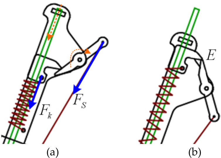
Working principle in the preparation phase of jumping: (a) Contraction of the SMA spring generates the motion of the hook relative to the body, (b) The crank and the hook at the transition point
This analysis is applied only to the preparation and the jumping phases of the jumping cycle. These two phases have a significant effect on the jumping height of the robot. As described in Sec. 2.1, at the end of the preparation phase the expansion spring is fully extended and the robot body lies at its lowest position (see Fig. 4(a)). This state may be called the full energy storage state. After this moment, the spring is unlocked and so the stored energy is released such that the body mass can be pushed to move upwards rapidly. However, the leg/foot part still stands on the ground. At the end of this release process, the spring recovers its original length and all the energy is released. This is called the verge of take-off state and can be seen in Fig. 4(b).

Simplified robot model: (a) State when the spring is maximally extended, (b) State when the spring energy is released
Let V be the velocity of the body module in this state. The motion of the body module from the first state to the second state satisfies the law of energy conservation. The elastic potential energy of the expansion spring at the start of the process should be identical to the kinetic energy of the body module at the end of the process. This equality relation is shown in (1) and the velocity V of the body module is obtained in (2) where l0 is the spring displacement:


One might note that after the second state, the body will collide with the leg/foot part (See Fig. 4(b) for this scenario). The collision is assumed to be perfectly inelastic. After the collision, two masses are “joined” together, and the whole robot now takes off from the ground with the common velocity v. The law of the conservation of momentum is applied for those moments before and after the collision, as in (3). In addition, the take-off velocity of the whole robot is computed in (4).


Note that when evaluating the jumping height of the robot, transverse motions are neglected. All of the energy from the spring is used for obtaining the jumping height, which is computed by the law of energy conversation in (5) and (6).


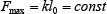
In (6), y max is the maximum jumping height that the robot can attain and g is the gravitational acceleration. Our robot employs one SMA spring as the only actuator. The SMA spring has a remarkably large strain, but the payload ability is limited. When a load heavier than 800 grams is applied to the SMA spring, the material may be destroyed. In the jumping robot, the load acting on the SMA spring is the elastic force of the expansion spring. One may deduce that the elastic force generated by the expansion spring must be limited to less than the maximum value F max , which is expressed in (7).
Next, the maximum jumping height of the robot is computed as (8). It is noted in (8) that although the elastic force of the expansion spring is set at the largest value, the jumping height can still be improved by increasing the spring displacement. This implies that even when the elastic force of spring is limited, one can improve the jumping performance by enlarging the spring displacement and reducing the spring stiffness. This is used as a guideline for our robot design.

2.3. Design of the landing mechanism
Landing is one of the most important abilities involved in consecutive jumping. In order to reduce the robot size and weight, the design of the landing mechanism should be designed in a very simple form. Since only one SMA spring is installed for the jumping mission, the landing motion must be implemented passively. The idea of a passive landing mechanism can be found in several jumping robots, such as a self-stabilization jumper [12] or a miniature jumping robot [4]. For these robots, cylindrical or spherical shells are utilized to enclose the robot body. The system of robot and shell behave similarly to that of a tumbler doll where the centre of mass is concentrated near the bottom. Due to the effect of gravity, the robots can recover their standing pose without any actuation. It is obvious that the passive stabilization method is suitable for simple robots like our own. In the actual design, a spherical frame is composed of the base with a ring shape and four circular carbon rods, as shown in Fig. 5(a).
Although the spherical frame is a necessary condition for landing stability, it does not guarantee stable landing in any condition. The position of the centre of gravity (COG) of the robot is another important condition. We present an analysis here to determine the conditions for the landing stability regarding the location of the robot's COG. The frame base is a platen ring that acts as the foot for the robot. Both the robot leg and the carbon rods are installed on the ring. The thickness of the ring is t. According to one theory [13], when the COG of the whole structure lies below the sphere's centre, the robot can recover its standing pose after the jump. However, in practice the effect of the ring thickness may put the landing in several critical situations.
Fig. 5(b) demonstrates a situation where the frame leans against the ring's edge. In this situation, the robot may fail to recover its standing posture. In the figure, C denotes the sphere's centre and T is the contact point between the sphere and the ground. In the same figure, M is the middle point of the ring. The frame leans on the ring at point S, which is the transition point. The vertical line drawn from S cuts the centreline CM at the point K. If the mass's centre lies on the right side of the vertical line SK, the robot is able to roll over the transition point so as to achieve a stable landing. Since the location of K is important for a stable landing, it is necessary to determine this position in the robot's design.

Spherical frame of the landing mechanism. (a) 3D model of the frame, (b) One critical situation in landing.
Let r and d be the radius of the sphere and the diameter of the ring, respectively. According to the configuration in Fig. 5(b), the distance from the limit point K to the bottom of the ring is computed as in (9).

Here, β is the angle between SK and MK.

The length of CM and TS are determined in (11) and (12).


Since the spherical frame is symmetric, the same critical situation on the right side is also considered. The calculation leads to the result that the COG of the robot must be arranged within the cone. The circular base of the cone is the ring and its apex is the limit point K. The cone holding the COG is seen in Fig. 5(a) where it is called the safety cone.3. Computer simulation
The results from the analysis in Sec. 2 provide a guideline for the design of the jumping robot. This section introduces a computer simulation to verify the theoretical results. All the simulation was conducted using Working Model 2D simulation software. A CAD model, which is made by AutoCAD based on the design model in Fig. 2, was directly imported into the simulation model. The friction coefficient between the robot foot and the ground was set at about 0.5, which corresponds to the friction coefficient of between wood and a wood surface. The masses of the body and the spherical cage were set at 13 g and 4 g, respectively. The cage diameter was set at 130 mm, which is about the robot's height.
The first simulation was conducted so as to verify the guidelines obtained from analysis of the effect of spring displacement on jumping height. Both the stiffness and the maximum displacement of the spring were changed, but the resultant spring force was kept constant. The simulation was performed with four samples and the results are shown in Fig. 6. It is obvious from the results that although the spring force is fixed, the jumping height of the robot can be improved significantly by increasing the spring displacement. This strongly supports the theoretical results obtained by (8).
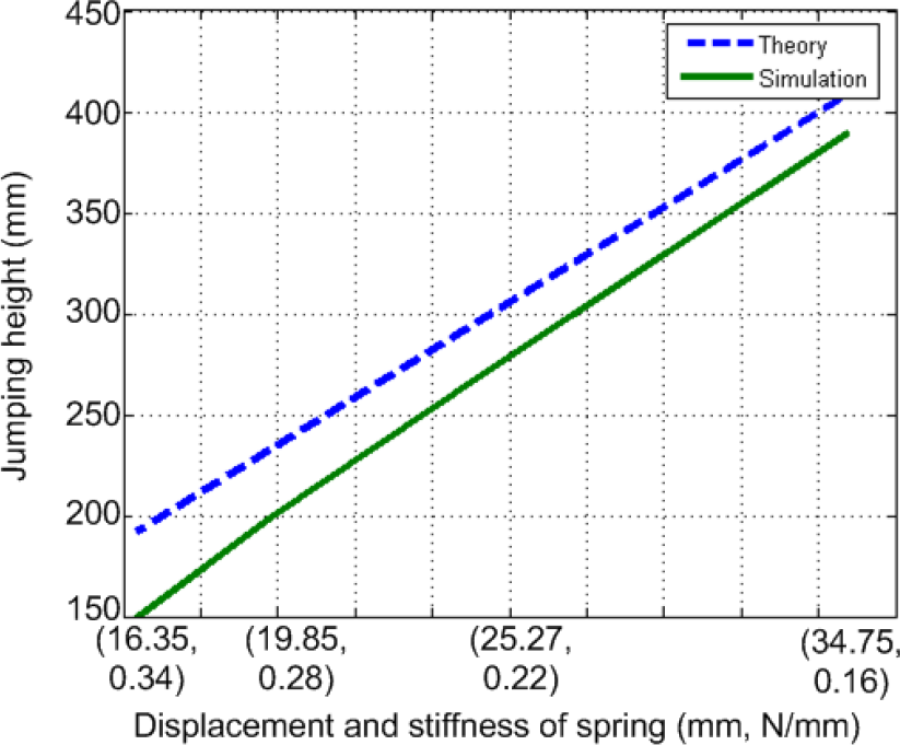
Jumping height for different spring displacements

Jumping height and distance to the change of tilt angles. (a) Jumping height. (b) Jumping distance.
However, a large displacement of the spring increases the cost of robot design in terms of size and weight. The third parameter set (l0 = 25.27 mm, k = 0.22 N/mm) in Fig. 6 is considered as a reasonable choice to increase jumping performance without enlarging the robot's size. Hence, it is used for the second simulation set. In this simulation, the structural parameters of the robot are fixed while only the tilt angle α is changed. See Fig. 2 for α. Fig. 7 shows the theoretical and simulation jumping heights and distances at various tilt angles.
It can be seen in Fig. 7 that the theoretical and simulation jumping performance are comparable. One may note that according to (8), the robot attains the best jumping distance when the tilt angle is at 45 degrees. However, such a large angle can cause a collision between the robot's body and the spherical frame when the spring is extended. It can also move the COG of the robot out of the safety cone, such that a stable landing might not be achieved as a result. Therefore, a tilt angle from 20 to 25 degrees might be a suitable choice for attaining a good jumping performance as well as a stable landing.

The robot and the jumping locus in simulation
The third simulation was conducted so as to validate the stable landing of the robot after jumping. The spring stiffness k and the tilt angle α were selected based on the first two sets of simulations. They were set at 0.25 N/mm and 20 degrees respectively. Using the actual configuration parameters from the design and simulation model, the location of the apex K of the safety cone in Fig. 5(b) was obtained. It was about 40 mm higher than the bottom of the robot, or 20 mm below the sphere's centre. In this simulation, the robot's COG was set at three different locations within the safety cone. The first position was close to the apex K of the cone, the second one was near to the base ring, and the third location was set at the middle of the cone. The robot was activated to perform the jump and its landing was evaluated. The simulation results show that for all of the conditions, the robot was able to recover its standing posture successfully after contacting the ground. Fig. 8 presents the jumping and landing motion of the robot.
4. Prototype and experiments
We fabricated a robot prototype such that it could have the same size and weight as the simulation model, i.e., a diameter of 130 mm and a weight of 17 g. It included a jumping mechanism enclosed by a spherical frame, as shown in Fig. 9. The jumping mechanism was mostly made of acrylic material. A steel spring with a stiffness of 0.25 N/mm was utilized as the energy storage device. A 6 mm coil expansion spring wound by 0.75 mm SMA wire was used as the robot actuator. The spherical frame was built from four carbon rods installed on the acrylic ring. Therefore, the mass of the sphere was much smaller than that of the jumping mechanism. The total weight was 17 gram with a battery and a control board included. The mechanism was designed so as to obtain a 25 mm displacement of the spring when the SMA spring is activated. The tilt angle of the robot body was set to be 20 degrees. The COG of the robot lied below the sphere's centre by about 30 mm, and so it is inside the safe cone. The SMA spring is controlled by a tiny 8-bit microcontroller via a MOSFET driver. All of the electronics components were mounted on a small circuit board that had a weight of 1 gram.
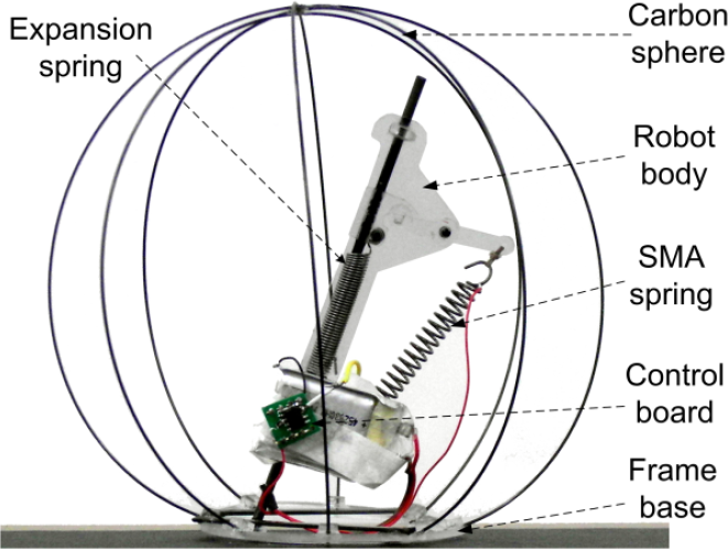
Robot prototype

The robot in the jumping experiment
Two kinds of experiments were conducted on the paperboard. The first experiment was done to verify the jumping performance of the robot. The second experiment was intended to validate the landing stability of the robot frame. We used a 3.7 V, 180 mA Li-Poly battery to supply the power for the control circuit and the SMA spring. The control board generated a PWM signal with a duty ratio from 0 to 100 percent to trigger the SMA material in a scheduled time period. As the result of 10 experiments, we found that the average jumping height was 200 mm and the average jumping distance was 160 mm. It was also found that after making the first contact with the ground, the robot keeps on rolling and the final position of the robot is about 400 mm apart from the initial position.
Jumping performance of the robot

The results are summarized in Table 3. It is remarkable that the robot can jump upwards to a height 1.5 times that of its body height and forwards 1.2 times the body length as well as landing stability. The results mean that the jumping performance of the robot prototype is about 50% and 90% compared to the theoretical and simulation models, respectively. The difference in the jumping performance is mainly due to the imperfection of prototype fabrication, though the prototype was made based on the simulation model. Another factor is the difference between the experimental conditions and the simulation conditions. Fig. 10 displays the snap shots and the moving path of the robot in one jump. From the take-off moment, it took about 0.4 seconds until the robot fell down to the ground. After touching the ground, the robot could roll passively with the support of the spherical cage and stop within about 1.25 seconds.
5. Conclusion
The paper presents the design, analysis, simulation and experiments of a mesoscale jumping robot. Only one SMA spring was employed so as to reduce the size, weight and complexity of the robot. The jumping of the robot is based on the energy storage mechanism that is found among natural jumpers like a froghopper or a flea. An unconventional spring-type SMA actuator is used as the robot's only actuator. For landing stability after jumping, a lightweight spherical frame is designed so as to enclose the robot's body. The robot is designed in order for its COG to lie inside the safety cone. By this design and the effect of gravity, the spherical frame can help the robot to remain in a standing posture after jumping. The optimum parameters in the robot's design, such as spring stiffness and the tilt angle, were found through mechanical analysis and simulation. Experiments with the self-contained 17 gram prototype show that the robot can jump up 1.5 times its body height and forwards by 1.2 times its body length Although the experimental results are smaller than those from the computation and simulation, they show a remarkable achievement in the development of a mesoscale jumping robot. As for the landing issue, the robot was found to recover its standing posture successfully after each jump. One of the remaining issues for the current robot is that of jumping time. Normally, it takes about 10 seconds to complete one jump. This is due to the slow contraction and release time of the SMA material. In the future, the jumping time is expected to be reduced by the application of a cooling mechanism. In addition to improving the jumping mechanism, the applicability of the robot to useful missions can also be enhanced by the study of obstacle recognition using sensors [14].
Footnotes
6. Acknowledgments
This paper was supported by Konkuk University in 2012.