
Abstract
Due to its advantages of realizing repeatable experiments, collecting data and isolating key factors, the bio-robotic model is becoming increasingly important in the study of biomechanics. The caudal fin of fish has long been understood to be central to propulsion performance, yet its contribution to manoeuverability, especially for homocercal caudal fin, has not been studied in depth. In the research outlined in this paper, we designed and fabricated a robotic caudal fin to mimic the morphology and the three-dimensional (3D) locomotion of the tail of the Bluegill Sunfish (Lepomis macrochirus). We applied heave and pitch motions to the robot to model the movement of the caudal peduncle of its biological counterpart. Force measurements and 2D and 3D digital particle image velocimetry were then conducted under different movement patterns and flow speeds. From the force data, we found the addition of the 3D caudal fin locomotion significantly enhanced the lift force magnitude. The phase difference between the caudal fin ray and peduncle motion was a key factor in simultaneously controlling the thrust and lift. The increased flow speed had a negative impact on the generation of lift force. From the average 2D velocity field, we observed that the vortex wake directed water both axially and vertically, and formed a jet-like structure with notable wake velocity. The 3D instantaneous velocity field at 0.6 T indicated the 3D motion of the caudal fin may result in asymmetry wake flow patterns relative to the mid-sagittal plane and change the heading direction of the shedding vortexes. Based on these results, we hypothesized that live fish may actively tune the movement between the caudal fin rays and the peduncle to change the wake structure behind the tail and hence obtain different thrust and lift forces, which contributes to its high manoeuvrability.
Introduction
As one of the most successful taxonomical groupings in the world, the fish occupies most of the water areas on earth. Their extraordinary swimming ability has attracted the interests of scholars for thousands of years [1]. As many recent studies have reported that fish can actively deform their fins to achieve different types of locomotion, more and more researchers have realized the importance of these flexible propulsion surfaces on enchancing ability of swimming. Such propulsion surfaces include dorsal fins [2–4] and pectoral fins [5–7] in body and caudal fin (BCF) propulsion and ribbon fins [8–10] in median and paired fin (MPF) propulsion. As the most conspicuous appendage of the fish's body, the caudal fin has also been studied extensively [11–15]. The use of bio-inspired devices has been one of the most pervasive methods for achieving insight into the hydrodynamic performance of the caudal fin [16–20]. For simplification, the fish tail has always been modelled as a simple foil, capable of conducting only two-dimensional (2D) flapping movements (heave and pitch) as an extension of the undulatory wave of the body [21], and hydrodynamic evaluation has accordingly been limited to thrust performance in the horizontal plane. The significant impact of heave and pitch motions on hydrodynamic propulsion has gained great attention [18, 20].
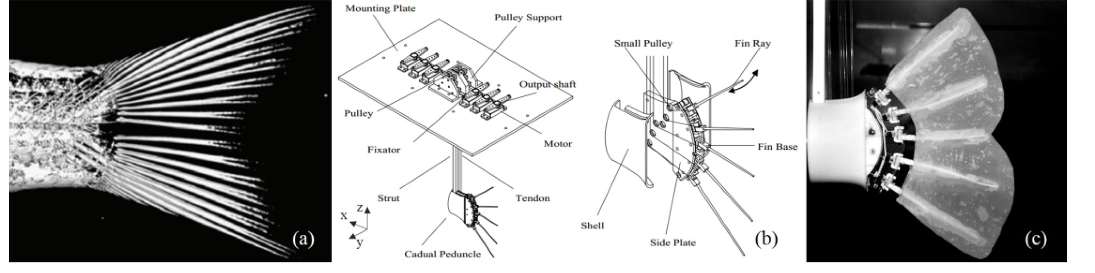
(a) Computer Tomography of Bluegill Sunfish caudal peduncle and fin rays [24]; (b) Illustration of the robotic model structure; (c) Snapshot of the robotic caudal fin
Nevertheless, a model that treats the fish caudal fin as a simple plate that performs only heave and pitch movements will be inevitably simplistic. For most of the ray-finned fishes, the caudal fin does not move only in two dimensions: under the control of the intrinsic musculature, the fin rays actively move as the fish swims, forming a complex three-dimensional (3D) propulsive surface [22–25]. Earlier studies on caudal fin active deformation investigated the hydrodynamic effects of different motion patterns and fin ray stiffness at a constant flow speed and found that this kind of three-dimensional motion may contribute to the fish's manoeuvrability [13, 26–27]. However, although the musculature of the caudal fin is seperate from the posterior axial body musculature, bony fishes are able to control the caudal peduncle and the fin surface simultaneously, so the three-dimensional caudal fin motion should not be considered separately. How do the kinematics of the peduncle and the fin rays together determine the locomotor performance of a caudal fin? How does the flow speed affect the locomotor forces and the wake flow generated by the caudal fin? Can we use a robotic experimental device to mimic both the caudal peduncle and fin ray motions and determine whether there is an optimal phase relationship between the two? To our knowledge, no experimental studies have yet addressed the above fish biomechanics issues, nor could any existing robotic system allow for the investigation of such questions.
In this paper, we established a scientific experimental platform to investigate the hydrodynamic function of the caudal fin with active 3D motion and peduncle locomotion. For this investigation, we first designed and fabricated a robotic model to mimic the tail of the Bluegill Sunfish (Lepomis macrochirus) and programmed it with movements that matched its biological counterpart. A heave and pitch robotic system was then implemented on the towing system, allowing for coupling of the fish caudal peduncle motion to the fin motions, and moved the robot in a forward direction under controlled speeds. Simultaneously, we measured the forces and kinematics of the robot at varied flow speeds. Two-dimensional wake flow analyses were conducted in the mid-coronal (x-y) and transverse (y-z) planes with the help of 2D digital particle velocimetry (DPIV). Three-dimensional wake structures in the mid-sagittal (x-z) plane were then obtained by performing 3D DPIV experiments. To conclude this paper, we discuss the use of bio-robotics as a scientific tool for investigating the hydrodynamics function of fishes and address the biological relevance of current experimental results. We also formulate several predictions and hypotheses for fish biomechanics.
Mechanical design and kinematic of the robotic caudal fin model
The design of the robotic caudal fin is based on the morphology and anatomical structure of the Bluegill Sunfish (Lepomis macrochirus) [24, 26] (shown in Figure 1a). The model includes five individual fin rays, which is the minimum number required to control the fin membrane surface. The rotation angle of each fin ray can be controlled precisely by a small servo motor to mimic the bending of the fin ray in vivo fish. The peduncle of the robotic model cannot move itself but is rather moved by the plate on which it is rigidly mounted, which can provide the heave and pitch motion (shown in Figure 2a). Further detail on the caudal fin model mechanical design and kinematic modelling can be found in our previous work [28].
In accordance with earlier research, the undulation movement pattern was assumed to generate the largest lift force [26]. To ensure the experimental results would be significant, we chose to apply peduncle motion to the undulation pattern and produce a wave to be transmitted along the caudal fin trailing edge dorsoventrally. Under the coordination system shown in Figure 3a, the undulatory wave can be expressed as:

where y u is the horizontal displacement of the fin ray tip; z denotes the vertical coordinate of the fin ray tip; t denotes the time instant; a u indicates the amplitude of the fin ray tip discursion; l is the chord length of the caudal fin; f is the motion frequency; λ is the undulation wavelength and Φ is the phase angle between the fin ray motion and the caudal peduncle motion. The locomotion of the caudal peduncle can be expressed as:

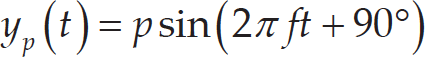
where y h denotes the caudal peduncle displacement in the horizontal plane; y p denotes the pitch angle around the vertical axis; h indicates the heave amplitude and p indicates the pitch amplitude. In this study, the phase difference between heave and pitch motions was set to 90° for all experimental trials.

(a) Schematic view of the experimental apparatus; (b) schematic view of the laser sheet position. We investigated the wake flow structure on three mutually perpendicular planes: mid-sagittal plane (x-z plane), transverse plane (y-z plane) and mid-coronal plane (x-y plane). The mid-sagittal plane is the initial plane of the robotic caudal fin model (before each trial, the fin rays of the caudal fin model all rest on the initial plane). The mid-coronal plane (x-y plane) is the plane denoted in panel (a) by the green area. It is parallel to the bottom of the tank and sweeps the mid fin ray of the model. The transverse plane (y-z plane) is a vertical plane, which is tangential to the trailing edge of the fin membrane. (c) Photo of the whole experimental system. The force transducer is shadowed by the bracket, but its position is still indicated in this panel. (d) Schematic of the 3D PIV experiment. The thickness of the laser sheet is broadened and two cameras are used to capture 3D velocity in this area.
Figure 2a shows the schematic view of the experimental platform for the hydrodynamic investigation. The water tank has a dimension of 7.8 m in length, 1.2 m in width and 1.1 m in height. A guide rail, actuated by a 4000 watt AC motor with a travel distance of 7.5 m, a position accuracy of 0.1 mm and a maximum speed of 3 m/s, is set vertically above the water tank. A servo towing system is used to generate precisely controlled towing speed (i.e., the speed of the oncoming flow towards the robotic model can be precisely controlled by towing the model forwards using the servo towing system). A movable plate is assembled with the carriage-integrated capabilities of both translational and rotational movements. The translational and rotational motions are actuated by servo motors and used to generate heave and pitch motions for the bio-robotic caudal fin model. The robotic caudal fin is designed to move at mid-depth of the water tank, to avoid the interference effect of the free surface and the bottom of the tank. Further detail of the towing system and water tank can be found in our previous work [29–30].
To measure the hydrodynamic force generated by the robotic caudal fin, a multi-axis force transducer (mini-40, ATI Industrial Inc., Canada) was assembled with the heave and pitch robotic carriage connected to the bio-robotic caudal fin model. The force transducer allows lift and thrust force to be measured simultaneously. The force data were then collected using a DAQ card (PCI-6284, National Instrument Inc., USA). The arrangements for visualizing 2D and 3D wake structures are different. For 2D visualization, the arrangement is shown in Figure 2a. The highspeed camera was used to record images of particle movement in the water. Flow was visualized by seeding the water with near-neutral, buoyant glass beads, 10 μm in diameter, which reflected light sheet from a 4 W laser with a wavelength of 532 nm. The laser sheet was projected in the water by several mirrors. The mid-coronal laser sheet was around 1 mm thick and 150 mm wide and was positioned at the x-y plane of the caudal fin. The transverse plane laser sheet was approximately 1 mm thick and 100 mm wide and swept the trailing edge of the fin membrane (y-z plane). Detailed understanding of the laser sheet position can be acquired from Figure 2b and its legend. Particle images of these two planes were recorded with high-speed cameras (SP-5000, JAI Inc., Denmark) at a frequency of 125 Hz. To avoid picture obscuration and guarantee suitable brightness, the exposure time was set to 2 ms. We then used commercial software, MicroVec (LiFangTianDi Inc., Beijing, China), to aid in the processing of the raw images, to obtain the velocity of each point in the calculation region. For 3D visualization, we modified the thickness of the laser sheet projected at the mid-sagittal plane (x-z plane) to 3 mm and used two cameras to record the movement of the particles along x, y and z directions at the same time (as shown in Figure 2d). Although the charge-coupled device (CCD) of the camera was no longer perpendicular to the object plane, we were still able to obtain clear particle images due to the large focus depth of our lens. Other variables in the experiments, such as the acquisition frequency of the camera, the glass beads seeded in the water and the laser generator, were the same as those used in 2D PIV experiments.
Results
Kinematics
Systematic tests were performed at fixed heave and pitch motion amplitude and frequency. The heave motion was conducted with f = 1 Hz and h = 10 cm, while the pitch motion was set to f = 1 Hz and θ = 10°. By controlling the towing system, the force measurements were conducted at three different towing speeds U: 0 cm/s, 5 cm/s and 10 cm/s. The amplitude, wavelength and motion frequency under undulation motion of the trailing edge were set to 20 mm, 170 mm (equal to the length of the caudal fin trailing edge) and 1 Hz respectively. To calibrate the amplitude of the fin ray tip discursion, we set a camera right behind the model (shown in Figure 2a) to record the trailing edge locomotion. Curves of the trailing edge from one flapping cycle were extracted from these images and are shown in Figure 3. To investigate the effect of phase angle between movements of the caudal peduncle and the fin rays on the hydrodynamic force of the bio-robotic caudal fin, the phase angle was systematically investigated between 0° and 315° at increment of 45°, while keeping the rest of the motion parameters under the undulation mode constant under towing speed of 0 cm/s. As the control group, we incorporated a no fin motion pattern (with all the fin rays stationary, making the fin membrane flat).
(a) Snapshot of the dynamic caudal fin from the high-speed camera. The yellow curve indicates the trailing edge of the caudal fin and the red arrows indicate the direction of individual fin ray movement. At U = 0 cm/s, trailing edge trajectories of the caudal fin under (b) no fin motion and (c) undulation during one flapping cycle are demonstrated.
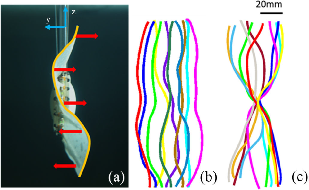
We first investigated the mean thrust force and mean lift force (averaged from one flapping cycle) generated by two different movement patterns (no fin motion pattern and undulation pattern with Φ = 0°) under different towing speeds. Mean thrust force and mean lift force data are shown in Figures 4a and 4b. It can be observed that the mean thrust and lift force of the bio-robotic caudal fin varied with towing speed U. For both of these movement patterns, mean thrust force decreased as U increased. This can be considered a direct consequence of increased drag force due to the lift of the towing speed. (Note the consequences of the way in which the force transducer is installed in this study. The thrust force measured here is actually the “resultant thrust force”. When the caudal fin is tested under a flow speed of 0, the measured force is the real thrust force generated by the model. When the flow speed is not 0, however, the force transducer will record the resultant force of the real thrust force and the water drag force.) At U = 0 cm/s, no fin motion pattern generated the maximum mean thrust force, with a force magnitude of 0.063 ± 0.001 N, 5% greater than the undulation pattern. As the towing speed increased to U = 5 cm/s, however, the mean thrust force produced by undulation motion with a magnitude of 0.008 ± 0.003 N exceeded the no fin motion pattern which was almost zero. At U = 10 cm/s, the mean thrust force became negative, which in turn indicate that the thrust force generated by the caudal fin was insufficient to overcome the drag force. In this situation, the mean thrust force of these two motions became −0.026 ± 0.002 N and −0.010 ± 0.001 N. The undulation again produced a maximum mean thrust force that was around 60% larger than no fin motion. When it comes to mean lift force, it is noteworthy that the mean lift force of the undulation pattern decreased significantly as the towing speed increased. The undulation motion generated mean lift force of 0.055 ± 0.009 N under U = 0cm/s, which was 17% and 400% larger, respectively, than those under 5 cm/s and 10 cm/s. As for no fin motion pattern, only very small mean lift forces were generated.
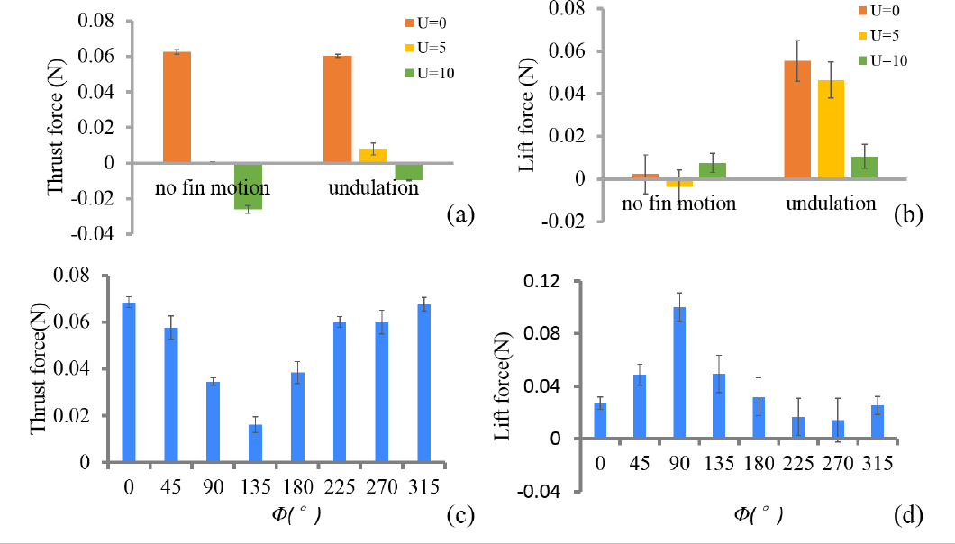
Mean thrust (a) and lift force (b) under U = 0 cm/s 5 cm/s and 10 cm/s for two fin movement patterns: no fin motion and undulation Thrust force (c) and lift force (d) as a function of phase difference (φ = 0°∼315°) between the caudal peduncle and fin ray motions were also investigated.
The force data from experimental groups with different phase angles are summarized in Figures 4c and 4d Again the differences between different trials on forces are obvious The mean thrust force reached its maximum value at φ = 0° and decreased as the phase angle increased up to 135° at which point the thrust force reached a minimal peak with a magnitude of 0.016 ± 0 003 N The peak-to-valley ratio was about 4 5 While mean lift force increased with phase difference up to 90° at which point the mean lift force reached a maximum peak with a magnitude of 0.100 ± 0 01 N and then decreased until the phase angle reached 270° The peak-to-valley ratio was about 8 0 Another interesting result is that we did not find a phase at which both thrust and lift force were maximum or a phase at which both forces were minimum.
Instantaneous force during two flapping cycles at φ = 90° and φ = 225° are shown in Figure 5 under which maximal and minimal mean lift force were generated among all phase tests The forces were significantly different in terms of both their profile and magnitude Pitch motion seemed to play a leading role in affecting instantaneous force When phase angle was 90° thrust force gradually decreased as pitch motion reached its maximum velocity, at which point it passed through the mid-position (Figure 5a) As the pitch motion reversed direction the thrust force gradually increased from a minimum negative value When pitch motion again reached its maximum velocity, the thrust force became almost zero. With the pitch motion from the mid-point to the other side of the extreme lateral position, the thrust force continued to increase. However, before the maximum peak thrust force, the profile became almost flat. Besides this phenomenon, the trend of the lift force profile was almost the same as that for the thrust force. As for φ = 225°, the trend of the force profile was nearly reversed. The maximum force at φ = 225° occurred in each case around the time when minimum force was reached at φ = 90°, and minimum force at φ = 225°. In addition, no apparent “flattening” phenomenon was observed.
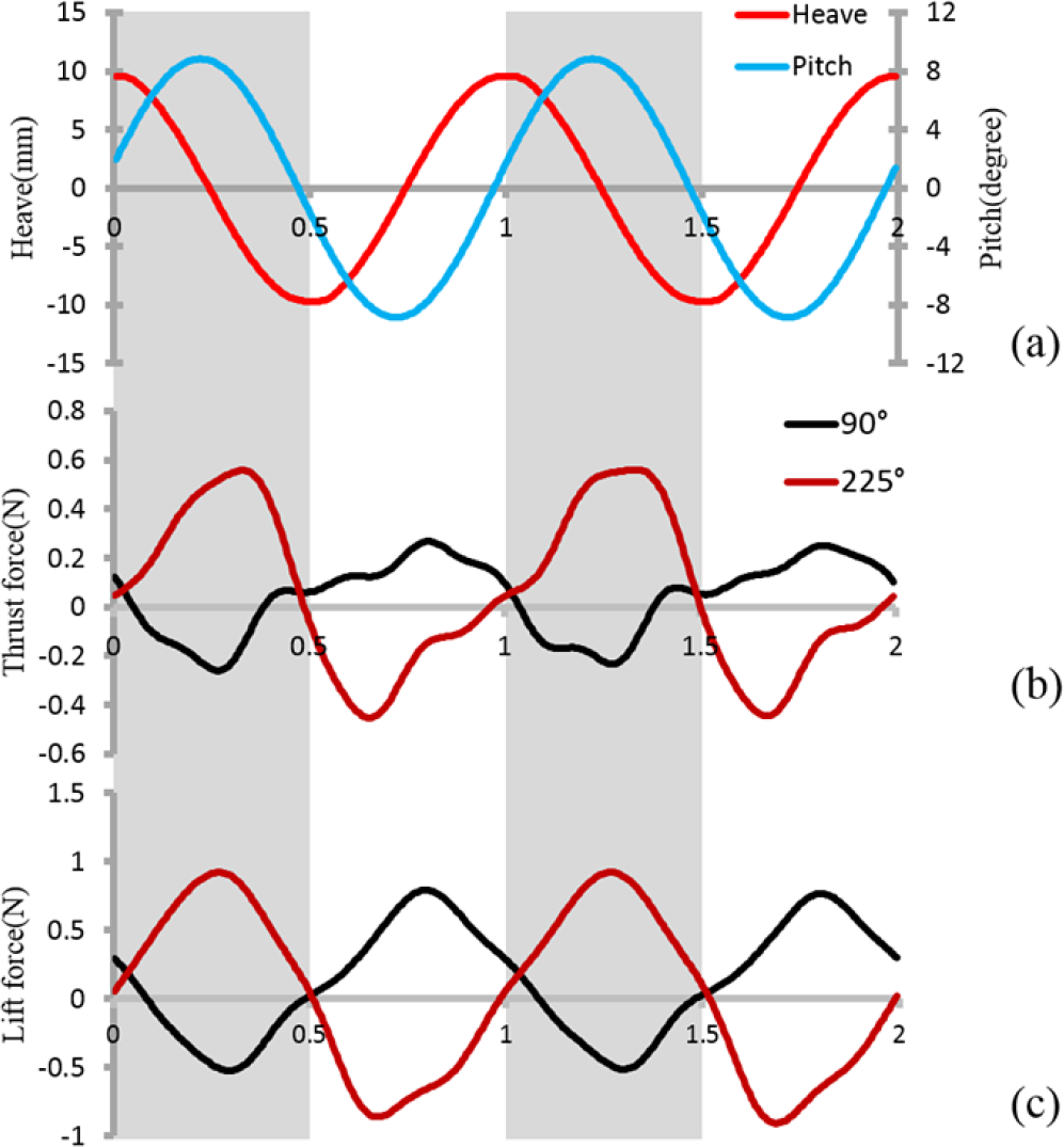
Instantaneous force for two caudal fin motion cycles (a) Heave and pitch motions for two motion cycles; (b) thrust force at φ = 90° and 225°; (c) lift force at φ = 90° and 225°.
We conducted DPIV measurements on the caudal fin with the no fin motion and undulation patterns at Φ = 0° in the mid-coronal transverse and mid-sagittal planes under zero towing speed (U = 0) The average wake jet velocities on the x axis in the mid-coronal plane the average wake jet velocities along the z axis in the transverse plane and the instantaneous velocity field at the time instant 0.6 T in the mid-sagittal plane are indicated in Figure 6, 7 and 8 respectively.
In Figure 6 it is clear that the average wake flows on the mid-coronal plane were totally different between the two patterns For no fin motion the caudal fin “pushed” the flow downstream (Figure 6a) with a relatively high speed In contrast the magnitude of wake flow speed of the undulation pattern was relatively small The result even indicates that the flow was “sucked” forward upstream (Figure 6b). Besides, the no fin motion movement pattern seemed to have more impact on the flow field in this plane, as the results show a much larger field of velocity under the no fin motion pattern than under the undulation pattern. For further comparison, we chose to measure average wake velocity on the mid-coronal plane in the U direction, marked in Figures 6a and 6b with a white dotted line. The average wake velocity profiles of the two motions are shown in Figure 6c. In the mid-coronal plane, the jet speed of undulation along the white line is close to zero, while the control motion generates significant jet flow speed, with a peak at around the middle position of an entire stroke (Figure 6c).

Average speed on the x axis in the mid-coronal plane based on the particle image velocimetry analysis. The colour red indicates the flow speed along the x axis in the forward direction and the colour blue indicates the backward direction. The white arrow in the chart marks the resultant flow speed direction of that point for: (a) no fin motion pattern; (b) fin undulation at φ = 0°; (c) average jet velocity along the white dashed line in panel (a) and (b) from the bottom to the top.
In the transverse plane, we recorded the wake flow of the upper lobe of the fin only (as the laser plane covers the upper part of the fin alone). The jet flow direction along the z axis of the no fin motion pattern was downward, overall (Figure 7a), which stands in sharp contrast to the flow generated by the undulation pattern (Figure 7b). For the undulation pattern, the flow in some regions went upwards while for some region it reversed. This phenomenon is also clearly reflected by the jet velocity, as can be seen from Figure 7c.
We obtained 3D velocity fields of the two motions in the mid-sagittal plane and chose a representative time instant (0.6 T) for comparison. Vorticity fields in this plane are also indicated (Figure 8). For the no fin motion pattern, the vorticity magnitude was significantly larger (indicated by darker colour) and the heading direction of the vortexes seemed to be parallel to the horizontal plane. For the undulation pattern, the vorticity magnitude seemed a little smaller (indicated by lighter colour) and the heading direction of the vortexes clearly deviated from the horizontal line. If we pay attention to the velocity vectors, we can find that, for the no fin motion pattern, the velocity magnitudes on both sides of the plane were generally equal, which means the water jet directed on both sides had equal velocity, in general. However, for the undulation pattern, it seems that the water jet was mainly formed on one side.
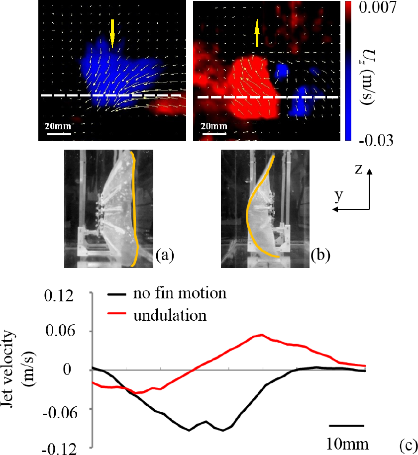
Average speed along the z axis in the transverse plane based on the particle image velocimetry analysis. The colour red indicates the flow speed along the z axis is the upward direction and the colour blue indicates the downward direction. The white arrow in the chart marks the resultant flow speed direction of that point for: (a) no fin motion pattern; (b) fin undulation at φ = 0°; (c) average jet velocity along the white dashed line in panel (a) and (b) from the left to the right.
Using a bio-inspired robotic model as a scientific tool for investigating animal locomotion
One of the biggest challenges in animal experiments is the intractability of living creatures [31]. It is hard to induce a hummingbird to fly through a wind tunnel [32], or a lizard to run across a water surface repeatedly [33]. Even if one can train a fish to perform given motions, measuring the quantities with which we are most concerned, such as the cost of transport, swimming efficiency, pressure near the body and thrust force generated by the flapping tail, is impractical due to the difficulty of designing measurement devices that can be put on the fish body [34]. We can, however, build machines to imitate the separate body parts of the fish, and thereby investigate the function of each component individually. By mounting sensors on this robot, we do not need to worry about harming any animals. By imitating the motion of the animal we are able to repeatedly test, and conduct quantitative analyses on, the motion performance. By isolating critical factors we can focus on the effect of a single element without the need for processing of complex data that incorporate too many irrelevant factors. Many studies have already successfully applied robotic models to the investigation of the mechanisms behind fish swimming [35–38].

Instantaneous velocity field at time instant 0.6 T in the mid-sagittal plane for (a) the no fin motion pattern and (b) the undulation pattern with φ = 0° and U = 0. The location of the caudal fin and the heave and pitch direction at this time instant are all indicated. The yellow dashed line marks out the middle caudal fin axis. The black arrows indicate the direction of the water jet produced. The length of the arrow is proportional to the velocity magnitude. The vorticity fields in the mid-sagittal plane are also shown in this figure, their magnitude represented by the shade of the colour.
In this paper, a bio-inspired robotic homocercal caudal fin model was developed to aid in the understanding of 3D caudal fin locomotion. We ensured that the most important morphologies, such as the shape of the tail, the pedunclelike shell and the tapered fin rays, were similar to those of a real fish. The motion of the fin ray and the peduncle was deliberately tuned to match result obtained from observation of real fish. Unfortunately, due to the limitations of material properties and the fabrication method, not all characteristics of the fish could be modelled (e.g., the number of fin rays and the elasticity of the fin membrane). However, given that the sole focus of this study is the way in which the caudal fin and caudal peduncle work together to affect hydrodynamic force, we can overlook these minor points.
The heterocercal tail can function asymmetrically, as indicated by its shape, when it is flapped in the water. The thrust force generated by the tail is not along the body axis, but rather at a certain angle relative to the mid-sagittal plane of the body. Existing research on shark tails has demonstrated this principle and highlights that this asymmetrical thrust force is critical in balancing the body and achieving high manoeuvrability [12, 39]. However, the evolution of the ray-finned fish tail has long been viewed as a transformation process from a heterocercal to a homocercal tail [40]. Since the asymmetric shape has diminished, it is plausible to conclude that the modern ray-finned fish does not need the caudal fin to provide a thrust force at an oblique angle. Yet, if we take the 3D motion of the caudal fin into consideration, a different perspective is revealed. The intrinsic muscle controlling the caudal fin has evolved into such a sophisticated mechanism that it can achieve complex 3D motion of the caudal fin membrane [24, 41–42]. Studies on real fish and robotic models have all demonstrated that even a symmetric caudal fin can realize asymmetric hydrodynamic function to aid the fish's manoeuvrability [26, 13].
Earlier research focused only on the fish caudal fin itself, including the movement patterns [13], fin ray stiffness [26], tail shape [20] and even membrane thickness [43], but overlooking the critical point that the fish tail is derived from the undulatory wave of the body and is attached to the caudal peduncle, which has a maximum lateral excursion of the undulatory wave [21]. If we take the motion of the caudal peduncle and the caudal fin as a whole, we can then introduce an important motion parameter, i.e., the phase angle Φ between the fin ray and caudal peduncle motion. By tuning Φ in our experiment, the mean lift force of the caudal fin varied significantly and the caudal fin presented different functional asymmetry levels (Figure 4). The effect of adding the caudal peduncle motion will be further discussed in section 4.3.
Effect of the peduncle motion
The peduncle motion introduces six additional independent motion parameters: the amplitude and frequency of the heave and pitch motion, the phase difference between the heave and pitch and the phase angle between the peduncle and fin ray motion. In this study, we fixed the first five parameters and only changed the phase angle between the caudal peduncle and the fin rays. We have demonstrated that, for a caudal fin that possesses the ability to move in a 3D pattern, the peduncle motion remains a critical motion parameter. When changing the phase angle Φ between the peduncle and the fin ray motion, the mean thrust and lift force were tuned simultaneously (Figures 4c and d). The instantaneous force was nearly inverted when Φ changed from 90° to 225° (Figure 5). Considering the coupling of the fin ray and peduncle motion together, Φ is more likely to determine the actual amplitude of each fin ray. As a result, the “enhanced” fin rays formed stronger jet flows while the “hindered” fin rays did not. This may explain why the wake structure behind the no fin motion pattern was symmetric (Figures 7 and 8a) but was asymmetric behind the undulation pattern (Figures 6 and 8b). This complex interaction between the 3D fin membrane surface and the water flow calls for further investigation.
Effect of flow speed
According to previous research and the DPIV results in this paper, the lift force was generated mainly because, when the fin rays were moving, the deformed surface of the caudal fin formed a jet flow that had a velocity component along the vertical direction (Figures 7b and 8b) [12, 13, 26, 39]. The greater the jet flow speed, the stronger the hydrodynamic force obtained; the larger the angle of the jet flow relative to the horizontal plane (the “jet angle”), the more force contributed to the lift force. In this study, we mimicked the oncoming flow towards the caudal fin model by towing the model in a water tank. According to our experiment results (Figure 4b), when flow speed increased, the mean lift force, which is critical to a fish's manoeuvrability in the vertical plane, decreased sharply. It seems that, when a fish is swimming at a high speed, vertical manoeuvrability is far less effectively achieved by caudal fin deformation than it is at low swimming speeds. The reason, then, that the lift force decreased along with the increased speed may be that, when the flow speed was enhanced, the jet flow generated by the flapping tail acquired an additional speed, which reduced the jet angle relative to the caudal fin middle axis. Similar phenomenon can be observed in other animals, such as sharks [25]. We further infer that the 3D caudal fin movement may have little effect on high-speed manoeuvrability. One natural phenomenon that supports this hypothesis is that fish species that are reported to possess the ability to achieve high swimming speeds always have a rigid tail, and do not seem to display caudal fin 3D motion [13].
Conclusion
In this study, we designed and fabricated a robotic caudal fin model as a scientific tool to help us investigate the hydrodynamic function and 3D locomotion of the caudal fin, in cooperation with the caudal peduncle motion. The morphology and structure of the model was designed to mimic its biological counterpart as closely as possible. An experimental system was developed to measure the hydrodynamic force and acquire wake flow structure simultaneously. Forces and average wake flows under different movement patterns were determined. Our experimental results and resulting predictions can be summarized as follows:
No previous research focusing on the caudal fin active deformation incorporated study of the peduncle motion [13, 24, 26]. The introduction of the heave and pitch motion had a significant effect on caudal fin propulsive performance.
By comparison with the no fin motion pattern, the active motion of the caudal fin generated significantly larger mean lift force. Obvious jet flow in the vertical direction and the asymmetric shape of the average flow field in the mid-sagittal plane suggest the symmetric caudal fin can still achieve asymmetric hydrodynamic function dorsoventrally.
In this paper, we have identified two factors that affect the thrust and lift of a caudal fin performing 3D motion: 1) the flow speed; 2) the phase between the peduncle and fin ray motion. The lift and thrust were tuned simultaneously by these two factors. The lift force slumped dramatically when flow speed increased, which may be attributable to the reduction of the jet angle. The relationship between the phase and the hydrodynamic force is complex and requires further investigation.
We hypothesize that live fish may actively control the caudal fin rays and the peduncle to obtain different thrust and lift forces, thereby contributing to its manoeuvrability at low swimming speeds.
The introduction of a mechanism that generates a controlled caudal peduncle-like flapping motion to a robotic fin ray system provides a new experimental avenue for the study of hydrodynamics of fish caudal fins, as well as other bio-robotic models involving 3D locomotion. In addition to answering fundamental biomechanical questions regarding fish swimming, the robotic device design method and the experimental results may also be applied to future non-traditional propellers [20]. The experiments described here focused on the caudal fin in a steady swimming state, but of equal interest is the hydrodynamics of the caudal fin in non-steady-states (e.g., acceleration, deceleration, turning, etc.). Future research will include more systematic parametric studies of caudal fin kinematics, conducting experiments under non-steady-state conditions and investigating wake flow structures under a greater number of movement patterns.
Footnotes
Acknowledgements
Many thanks to Cai Yingjie, Wang Yueping and Wang Zaijun for their help in implementing the experimental apparatus and programming the motion of the robotic fin. This work was supported by the National Science Foundation support projects, China under contract number 61403012 (to Li Wen), Beijing Science Foundation support projects under contract number 4154077 (to Li Wen) and National Science Foundation support projects, China under contract number 61333016 (to Tan Min). This article is a revised and expanded version of a paper entitled Bio-robotic flexible model for experimentally investigating the locomotor function of fish caudal fin, presented at the International Conference on Climbing and Walking Robots (CLAWAR), Hangzhou, Zhejiang Province, China, 6 – 9 September, 2015.