
Abstract
This paper presents a simple relative positioning algorithm for multiple micro robots. The micro robot is designed as a differential driven vehicle and actuated by MEMS-based electromagnetic micromotors. A simple relative positioning approach based only on one infrared emitter, receiver and compass is presented. Using this method, we characterized the accuracy of positioning between robots and identified sources of imprecision. Finally, this module is clearly demonstrated with the autonomous docking of multiple micro robots. The ability of our algorithm makes it cost effective and easy to deploy its application to multiple micro robots.
1. Introduction
To facilitate automatic operations in micro factories, narrow pipes, high-risk environments etc., autonomous micro mobile robots are in high demand. However, in practice, miniaturization of robots limits the development of the individual intelligence of each robot. This limitation leads us to employ multiple micro robots, which can exchange sensor information and collaborate to complete task. Due to low cost, versatility, scalability and robustness, research on the application of multiple micro robots has drawn much attention in recent years, such as mapping and exploring [1], handling μm-sized or nano-scale objects [2], collaborating to inspect industry equipment [3] and so on. For several tasks such as distributed coverage [3], dispersion behaviours for a team of multiple miniature robots [4], movement in formation [5] and knowledge of a robot's own localization or that of neighbouring teammates is required.
Localization systems of multi-robot teams can be roughly classified into two main categories: absolute and relative positioning systems [6]. Absolute localization determines the robot's position in a global coordinate framework, such as the global positioning system GPS [7] and uses an overhead camera system [8]. Relative localization also is called egocentric localization, where each robot attempts to determine the position of other robots in its own coordination system. For many multi-robot behaviours, only relative localization range and bearing information is needed. For example, a team of robots executing formation behaviour need not know their absolute localization, but must know the relative positions of their neighbours. Relative localization problems are also more important for swarm robots that search for targets using relative localization. Relative localization can also be obtained with an absolute positioning system, but some situations do not allow for effective global localization, which is less scalable than relative localization.
Section 2 of this paper provides related work on multi-robot relative positioning. In Section 3 we describe the technological design of our module for a micro robot. In Section 4 an approach for determining the range and bearing between robots using the module is presented. The relative localization characterization is demonstrated in Section 5. In Section 6 we demonstrate the effectiveness of this method in experiments of multiple micro robots docking. The paper ends with conclusions and proposes future work.
2. Related work
A majority of previous works on relative localization research is on bigger robot, but little research has been done on miniature robots, especially centimetre-scale robots. Numerous methods have emerged to address multi-robot localization such as Monte Carlo localization [9], Markov localization [10] and other localization systems based on landmark recognition [11]. However, those methods tend to need complex hardware and a high computing power, such as laser range finders and cameras, which are not suitable for centimetre-scale micro robots.
It is preferable to use radio signals for relative positioning [12–13]. Radio localization can be used over much longer ranges and is not sensitive to miscalibration. However, it is hard to very accurately measure signals and this causes greater energy consumption, so radio signals are also unfit for centimetre-scale micro robots.
Another low-cost method of relative positioning is to use synchronized ultrasonic and radio emissions to signal other robots by computing time-of-flight between radio and ultrasonic signals. Ultrasonic-based relative positioning can be very accurate, especially over longer ranges. Using this type of system, in [14] there is a finished average bearing error of 1.84° and an average range error of 0.375cm up to 810cm. In [15] this type system is also used, which has a precision of 0.8cm and 3° over a 6.7m range. Ultrasound is more able to pass through solid objects than infrared (IR), making ultrasound systems less sensitive to occlusion. However, a problem with ultrasound is that signals are slow to dissipate, especially in enclosed environments. Ultrasonic size and weight is also large for centimetre-scale micro robots. From what we have mentioned above, radio-based and ultrasonic-based relative localization systems do not offer a viable solution for multiple micro robots.
Relative positioning based on a low-cost IR sensor is a good choice for multiple micro robots. Firstly, IR signals are very fast, which may increase robot localization velocity, with the signal duration potentially being in the order of microseconds. Secondly, IR sensors may also be produced on a very small scale for micro robots. Yet, using received signal strength indication (RSSI) to calculate range and bearing is susceptible to interference from external signals including environment temperature and light. IR light can also be obstructed by a robot or some other obstacle, which could prevent the signal from accurately reaching other robots. However, this could, actually be a benefit in some scenarios, where robots need to know whether or not they are in the line-of-sight of each other. This kind of system is present in research such as [16–17]. In [17], the system had a maximum range of 3m with a maximum distance error of 8% of range and a maximum bearing error of 17.4° (7.00° on average). In [6] this is improved by using a fast on-board relative positioning module for the multi-robot system. The system has a maximum range of 3m with a maximum distance error of 6.56% of range and a maximum bearing error of 8.25°. The system includes eight evenly spaced IR LEDS and eight IR photodiodes around a Kherpera III robot. In [18] another IR-based system is presented, which achieved good performance with a 1cm error and 2° error at a range of 30cm. However, the system has a maximum range of 250cm and a smaller, unspecified maximum range that provides reliable positioning.
However, the systems above rely on an IR emitter and an IR receiver, which is not fit for centimetre-scale micro robots.
The major novelty of this paper is a simple relative positioning method only based on one infrared emitter, receiver and compass for multiple micro robots. Moreover, the relative positioning method described in this article is more flexible, accurate and requires less memory and scale. Although it cannot achieve greater accuracy than existing ultrasound-based solutions, it is better than radio-based and previous IR-based designs. The ability of our algorithm makes it cost effective and easy to deploy its application to multiple micro robots.
3. Micro robot and positioning module
3.1 Micro Robot
Our centimetre-scale mobile autonomous micro robot, which mainly consists of three wheels, is designed as a differential driven vehicle with two identical standard wheels and a caster [19]. The volume is 28*28*30mm, as shown in Fig. 1. Each standard wheel is directly actuated by a 6.8mm micromotor, which is designed as a 3-phase permanent synchronous motor with star-connected windings and employs an axial flux structure that can reduce the volume compared with radius flux [20]. The micro robot platform is designed and integrated, including a microcontroller base on ARM7, a driver of the electromagnetic micromotor, a RF wireless transceiver, infrared proximity sensors and a power manager. In addition, some additional input and output CPU ports are reserved which provide our relative positioning module joint.

Photograph of basic micro robot with a 22mm coin.
3.2 Relative Positioning Hardware Design
Choosing the components of the relative positioning system of the micro robots is still a challenge. On the one hand, the available space for a circuit is limited because of their smaller volumes, which means that we must choose those highly integrated microelectronic components with a tiny size; on the other hand, the power consumption should be reduced as much as possible due to the lack of high-capacity micro-batteries. For these reasons, we chose a low-cost, tiny, energy consumption IR sensor and compass to achieve multiple micro robots' relative positioning. The relative positioning system consists of one IR emitter, an IR receiver and a compass. There is a Ω1.8mm focused IR emitter (BPW17N from Vishay) with a half-angle of 12° and a Ω5mm IR receiver (SFH203P from OSRAM) with a half-angle of 75°. The IR emitter is placed around the micro robot and the IR receiver is set at its centre of rotation. A compass (MMC212 from MEMSIC)is placed the middle of the IR emitter and the IR receiver, the x-axis of which lines up with the IR emitter and the IR receiver, as shown in Fig. 2. Though the half-angle of the IR receiver is only 75°, its conversion ratio is still up to 40% when the incident angle of its receiving IR light is equal to 90°, so it can be used as an omnidirectional receiver on the plane to effectively perceive the IR light from all directions.

Arrangement of IR sensors and compass and virtual arrow direction indicates common reference direction.
A key point of an infrared positioning system design is how to determine the drive current of the infrared emitter. A smaller driving current has a shorter infrared measuring distance. On the contrary, a larger driving current leads to infrared receiver saturation in a shorter distance, thus it cannot measure over a shorter distance. Furthermore, a larger driver current consumes more energy. Considering those factors, an 8mA driving current is chosen.
In the relative positioning system, the emitter is driven by Half-bridge drivers 1 of ATA6836 (driver of micromotor) with a driving current of 8mA. The output voltage of the IR receiver is converted by 10-bits ADC of a microcontroller. The compass is driven by the I2C port of the microcontroller.
3.3 Communication
During relative positioning we turn to infrared communication for help. The infrared communication data packet format is shown in Fig. 3.

IR communication packet format
Broadcast mode communication is used for obstacle detection and information sharing with neighbouring robots. In this mode, one IR receiver detected all data broadcasted by the IR emitter. The flowchart for confirmation-based message communication techniques is shown in Fig. 4. In these scenarios, after receiving another micro robot's message, the micro robot will transmit its own message packet to initiate their connection and wait for an acknowledgement message in a defined time. If the micro robot does not receive any acknowledgement response, it will eliminate the connection request. The robot's communication bandwidth is determined by several parameters, including the IR-component's switching rate, the main processor performance, the experimental environment and so on. In this system, the communication bandwidth is 100bps. The maximal translational speed of robot is 6.4cm/s. The communication bandwidth can meet the requirements of the relative localization module.
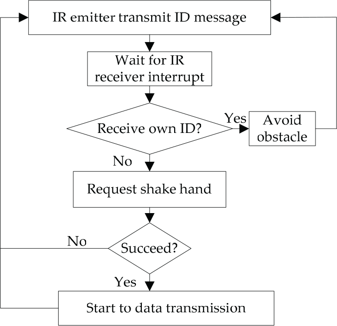
Confirmation-based message communication
4. Relative positioning approach
Our presented relative positioning approach is based on infrared sensor and compass. We describe the core localization algorithm with two neighbor robots, R1 and R2 that generates relative positions, which is shown as Fig. 5. Each robot which attaches a compass (the magnetic sensors) has common reference direction which is shown in Fig. 2 virtual arrow direction. Because the presence of magnetic interference around the magnetic sensors (hard magnetic interference, soft magnetic interference), making the measured local magnetic field is the vector sum of the local geomagnetic field and the local magnetic field, we take calibration before using compass. The origin of robot's local coordinate system is defined as the center of robot's rotation. IR emitter transmitting direction is the heading direction of robot. The principle of a simple relative positioning approach based on infrared sensors and compass is illustrated by the following five phases, including search, adjust, measure, calculate and amend.
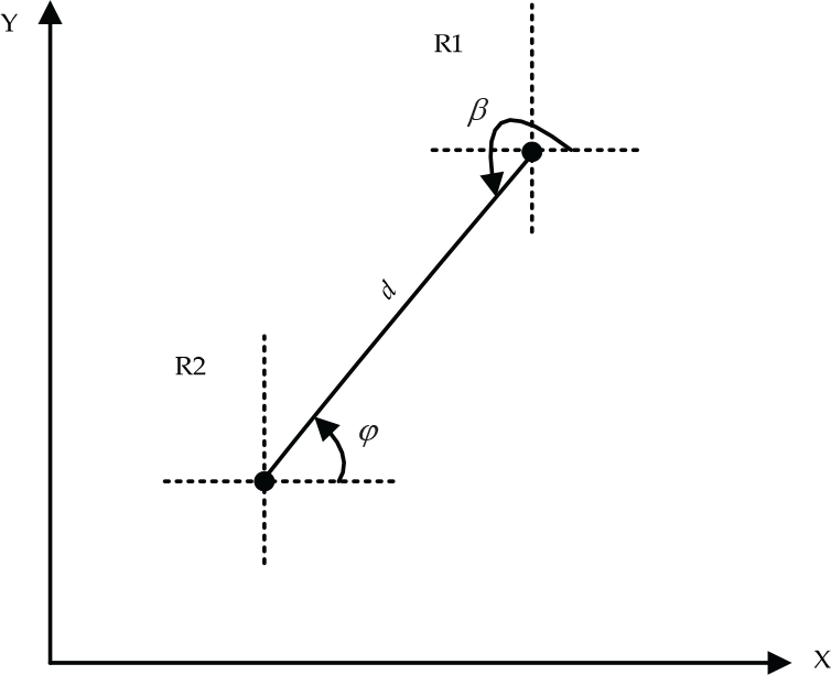
The φ, β and d is desired value in relative localization system
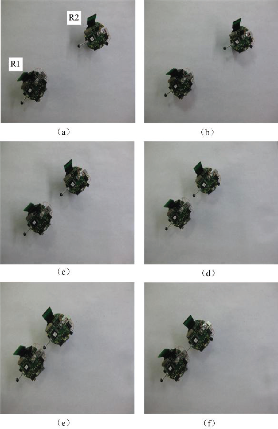
Search: The micro robot R1 wants to determine the R2's localization in its own coordinate system. The initial status of R1 and R2 is shown in Fig. 6 (a). Let R1 steer ±180° in situ to search for R2, until R2 receives the signal from the IR emitter of R1 (as shown in Fig. 6 (b)). After that R2 behaves in the same way to search for R1. This is because that the initial relative position and orientation between R1 and R2 are unknown when positioning begins and the IR emitter also has a beam angle. Therefore, it is possible that they cannot receive the signal from each other, so the search strategy above is adopted to solve the problem.

Process of relative positioning between two micro robots
Adjust: R1 steers micro-step in situ until R2 receives the maximal signal strength from the IR emitter of R1. The IR emitter has a maximal relative radiant sensitivity at 0 angle, which makes sure accurate positioning is achieved with less errors (as shown in Fig. 6 (c)).
Measure: After that R2 searches for R1 in the same way and steers micro-step in situ until R1 receives the maximal signal from the IR emitter of R2. R1 records the maximal signal strength from R2 and obtains the distance value by the distance estimation table, as shown in Fig. 6 (d).
Calculate: After measuring the distance, R1 and R2 read their own compass value φ1, φ2. φ1 is the R2 direction value in R1's own coordinate system and φ2 is the R1 direction value in R2's own coordinate system.
Amend: R1 and R2 transmit their respective measurement distances d1 and d2, of which the average check value d is the distance between R1 and R2.
If there are two or more robots requiring localization, the robot deals with them according to time order.
5. Relative localization system characterization
The accuracy of the relative positioning system is very important for a centimetre-scale robot. In order to effectively judge the accuracy of our positioning system, a thorough characterization of the robot's responses at different ranges and bearings is necessary. The overhead camera positioning system shown in Fig. 7 was used to provide ground truth measurements of robot positions during positioning. In this section, we evaluate our relative positioning system from different aspects.

The overhead camera positioning system
5.1 Intensity versus Distance
To convert the received IR intensity into a distance, it is necessary to manually measure range terms at different distances to create an accurate lookup table under ideal conditions, which is shown in Fig. 8. We assume that the minimum range possible is 20mm, as the RSSI reaches its maximum value around this distance. The RSSI drops off rapidly as distance increases up to approximately 50mm and then gradually decreases up to a maximum range of 150mm. This results in much more accurate intensity measurements for small distances, since RSSI variation has less effect here and less accurate measurements for large distances that are heavily influenced by changing RSSI values.

Intensity curve of IR sensors
5.2 RSSI Noise
In order to determine the accuracy limitation of our positioning system, it is necessary to know how much noise measured RSSI values contain. If we have very noisy RSSI measurements, it will be impossible for us to obtain very accurate range and bearing measurements. To do this, we measured the percentage variation in RSSI between two stationary robots for receivers with angular offsets of 0°, 45° and 225°. This was done at ranges of 30mm, 50mm and 150mm. The results can be seen in Fig. 9. The variation in RSSI is quite small in all cases, particularly for ranges of 30mm and 50mm, where standard deviation remains below 0.5%. Variation remains below 4.5% at a range of 150mm. The consistency of these measurements implies that if RSSI variation was the only source of error, we should be able to obtain highly accurate measures of range and bearing even for ranges up to 150mm.
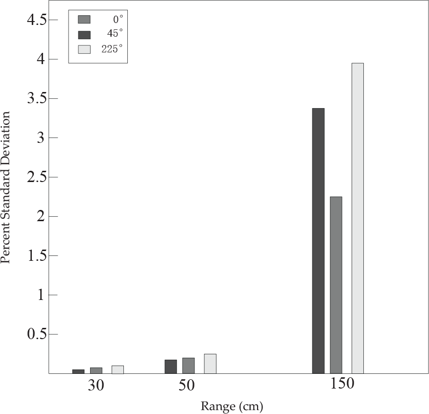
Standard deviation for 100 RSSI measurements from IR receivers a different angular offsets and distances
5.3 Bearing Accuracy
We used two robots to verify our relative positioning algorithm. The experiments were executed on an even surface with relative positioning of micro robot R1 and R2. We “fixed” the position of robot R1 and moved robot R2 through 36 different bearings (step size of 10°) at distances of 30mm, 100mm and 150 mm. We took 50 bearing measurements at each position. The amount of error for different bearings can be seen graphically in Fig 10. The maximum mean bearing deviation is 6.38° at a 110mm range. The mean measured bearing generally remains close to the actual bearing, though it does vary both above and below. These variations are the result of the robot steering movement during relative localization, which introduces error into measurement.

Bearing error versus actual bearing for ranges of 30mm, 50mm and 100mm
5.4 Range Accuracy
We now study the accuracy of the distance measurements given by the range term using the previously described lookup table. We again fixed the position of a transmitting robot and moved a receiving robot through 36 different bearings (step size of 10°) at 16 distances between 20mm and 150mm (step size of 10mm). We observe the mean of the measured distance across all bearings, with 50 measurements at each bearing. The results are shown in Fig. 11. The average measured distance is quite close to the actual distance in all cases: the maximum mean distance deviation is 8.8mm at a 130mm range.
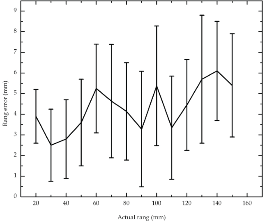
Measured range versus actual range across 36 different angular positions at each distance
5.5 Error Analysis
Theoretically, our algorithm does not have error, but it does have error in its practical application. There are three major reasons for that. Firstly, mechanical part inaccuracies and rotation slip during relative positioning introduce the error. Secondly, sensor noise affects the positioning accuracy. Compass measurement errors exist due to the uneven distribution of local magnetic fielded noise even when using the compass calibration procedure. The IR sensor measurement is susceptible to environmental factors such as brightness, temperature and humidity. Finally, rotation speed and communication speed affect sensor sampling and thus introduce error to the relative localization system.
In reference to [6], an on-board relative positioning module for mobile miniature robots is presented, which operates using modulated IR signals. A comparison of the performance between the method in [6] and our method is shown in Table 1. We can see the method in [6] is faster than our performance. Furthermore, it can operate at a greater range, which is unfit for small size micro robots due to more infrared sensors and a bigger driving current. Our method has a better bearing and range measurement performance than the method in [6]. Our method can operate at a shorter range and this could actually make up for the disadvantage of the short range in the method in [6].
The performance comparison between two methods

6. Experimental evaluation
In order to validate the effectiveness of our relative position method, we focus on the task of the autonomous docking of a self-reconfiguration micro robot. Our relative position method is also applied to a situation with more IR emitters. On-board the robot in [19], the compass is placed in the middle of IR emitter #1 and the IR receiver and the x-axis of the compass lines up with IR emitter #1 and the IR receiver, as shown in Fig. 12.

Arrangement of IR sensors and compass on the robot in [19] and virtual arrow direction indicates common reference direction
The docking experiment was done on an even surface with one object unit (R1) and one approach unit (R2). The approach path panning uses the control law described in [21] and uses a feedback controller based on the relative localization between R2 and R1. The linear control law is induced:

where kd is the control coefficient of v, kφ, is ω control coefficient d and φ is shown in Fig. 5.
At the beginning, the orientation of R2 is adjusted in situ until R1 receives the greatest IR intensity from IR emitter #1 of R2. Next, the orientation of R1 is adjusted in situ until R2 receives the greatest IR intensity from IR emitter #3 of R1. Then R2 approaches R1 by adopting the path planning method above until the male connector of R2 touches the female connector of R1. Finally, the male connector of R2 plugs into the female connector of R1. Meanwhile, it is judged whether the insertion action is completed successfully by detecting changes in the conduction status between the cover and base of the female connector of R1. If the insertion is successful, the female connector of R1 is closed by changing the orientation of its latch. Some scenes of the experiment are shown in Fig. 13.
Some scenes of docking experiment for self-reconfiguration micro robot
A variety of initial positions and orientations relative to each other were tested in the range of 40mm-150mm and 0–360° and docking was successful for all thirty trials.
In a comparison between our approach based on relative localization and [19], the finish time here is less than in the range of 40mm-150mm. The further the range is, the more obvious the advantage is. For this reason, [19] uses open-loop control, while our path planning uses the close-loop control based on relative localization. A close-loop control will always outperform an open-loop control. The resulting trajectories of open loop controls are usually not smooth, because the transitions from one trajectory segment to another are, for most of the commonly used segments (e.g., lines and part of circles), not smooth. This means there is discontinuity in the robot's acceleration, so it takes more time than close-loop control.
7. Conclusion and future work
We have presented a relative positioning module for multiple micro robots, which operates using one IR emitter, one receiver and one compass. A general technique for calculating the range and bearing between robots has been described and applied specifically to our module. The performance of the module has been characterized and the error source has been identified. The system has been shown to enable fast docking for multiple micro robots without global positioning and is a significant improvement over existing work reported in the literature. The ability of our algorithm makes it cost effective and easy to apply to multiple micro robots where global positioning is not essential and only relative positioning is required, such as multi-robot formation, docking of self-reconfiguration micro robots and search and rescue.
Our method of relative positioning has some advantages: (a) no accumulator error: it localizes without using historical positioning information; (b) distributed: a micro robot localizes only using own sensors; (c) low complexity: only using a small amount of data processing; (d) accuracy: which has been characterized in Section 5. However, the system is susceptible to interference from environmental fluctuations and external disturbance, such as magnetic fields, which affect the senor measurement accuracy and therefore affects the accuracy of the system. In the future measures will be taken to solve this, for example digital filter implementing.
Footnotes
8. Acknowledgments
This work was supported by the National Natural Science Foundation of PRC (No.61175100 and No.51275285), the Postdoctoral Science Foundation of China (2012M510087) and the Research Fund of Medicine and Engineering of Shanghai Jiao Tong University (No.YG2011ZD01).