
Abstract
A modular mobile self-reconfigurable microrobot is developed to enlarge the whole surveillance range of mobile microrobot. The microrobot is designed as differential driven vehicle equipped with a passive universal connector with autonomic engagement/disengagement function, and actuated by MEMS-based electromagnetic micromotors. To realize that the microrobot is autonomous, its electrical system is designed in modularity and integrated. A simple autonomous docking approach based on infrared sensors is presented. Experimental results verify high efficiency and reliability of the proposed docking method, and demonstrate the improved ability of performing large-range vision-based surveillance by power and communication relays.
Introduction
The research on distributed mobile microrobot has drawn much attention in recent years, because they not only have advantages of low cost, versatility, scalability and robustness, but also have broad application prospects in the limited spaces and special environments, such as narrow pipe, microfactory and other hazardous places inaccessible to humans. Some modular heterogeneous/ homogeneous mobile microrobots with various highly integrated and specialized sensors have been also developed to prove the value of collaborative swarm. In the distributed microrobotic systems, team members can exchange sensor information, and collaborate to search for and track objects (McLurkin, J., 1996; Fukuda, T., et al., 2002), map and explore unknown environments (Grabowski, R., et al., 2000; Correll, N. & Martinoli, A., 2006), or handle μm-sized or smaller nano-scale objects (Brufau, J., et al., 2005; Woern, H., et al., 2006). However, their whole operating range is generally very limited because each individual has limited energy and short communication distance caused by scaling effects.
Modular self-reconfigurable robotic system is a collection of unlimited numbers of distributed homogeneous/heterogeneous robots with uniform docking interface. This kind of robot can change their own shape by reorganizing connectivity of their parts in order to enhance mobility, adapt to new circumstances, perform new tasks cooperatively, or recover from damage. According to the geometric arrangement of their units, this kind of robots generally can be classified into three categories, including lattice-type (Ostergaard, E. H., et al., 2006; Zykov, V., et al., 2007), chain-type (Yim, M., et al., 2002; Castano, A., et al., 2002) and mobile-type (Fukuda, T. & Nakagawa, S., 1998; Hirose, S., et al., 2000; Bererton, C. & Khosla, P. K., 2001; Brown, H. B., et al., 2002; Hensinger, D. M., et al., 2002; Gross, R., et al., 2006; Zhong M., et al., 2008; Wang, W., et al., 2010). Among the three types above, it is easier for lattice-type and chain-type to realize self-reconfiguration because of their indivisible whole structure, but they can not carry out tasks alone for lack of mobility. In contrast, mobile-type is composed of independent moving units, and thus they can be also separated to form a distributed robotic system. Therefore, the mobile-type has the advantages of both distributed robots and self-reconfigurable robots. For self-reconfigurable robot, two of its key technologies are respectively design of connect mechanism and implementation of autonomous docking. Due to complicated mechanical structure and control approach, few reports on the self-reconfigurable microrobot with several centimeters are available up to now. Here, Yoshida developed a reconfigurable microrobotic system using shape memory alloy, the unit of which can realize rotational motion by using an actuator mechanism composed of two SMA torsion coil springs, and various shapes can be formed by a group of identical mechanical units (Yoshida, E., et al., 2000). Takeda developed a mobile reconfigurable microrobot with an electrical and mechanical connector by using MEMS technology for inspection of outer tube surface, and the task is carried out cooperatively by several units which gather and are connected with each other at the desired place (Takeda, M., et al., 2000). However, these microrobots are not self-reconfigurable.
In this paper, our objective is to enlarge the whole surveillance range of mobile microrobot by adopting the method of power and communication relays and the self-reconfigurable robotic technology. For this purpose, a modular mobile self-reconfigurable microrobot (named MNRIBot) actuated by MEMS-based electromagnetic micromotors is developed. In the system, each basic robot is not only an ordinary power relay unit which can link with the one with special sensor automatically and pull it to further places, but also a router that can relay messages for their neighbors, thus to enlarge their whole surveillance scope by the two kinds of relay methods.
This paper mainly focuses on design and docking of the mobile self-reconfigurable microrobot, and we also show how the team members can exploit collaboration to perform large-range vision-based surveillance. The outline of the paper is organized as follow. Section 2 presents the structures of electromagnetic micromotor and microrobot. The design and integration of electrical system of the microrobot is given in section 3. Section 4 presents a simple autonomous docking approach based on IR sensors. Section 5 presents the experiments of docking implementation and multi-microrobot cooperation, followed by the conclusion in Section 6.
Electromagnetic Micromotor and Microrobot Structure
Electromagnetic Micromotor
Microactuator is one of most critical components of the microrobot. Compared with other varieties of micromotors such as electrostatic, piezoelectric, ultrasonic, and shape memory alloy, the electromagnetic micromotor has larger output torque and higher efficiency in the same volume (Dario, P., et al., 1998). In this paper, two different sizes of electromagnetic micromotors are designed and manufactured as the driver of the microrobot, the diameters of which are 4.5mm and 6.8mm respectively. The former is used in the connection mechanism, and the later is employed in the locomotion mechanism.
The electromagnetic micromotor is designed as 3-phase permanent synchronous motor with the star-connected windings, and employs axial flux structure which can reduce the volume compared with radius flux (Li, Z. B., et al., 2007). It is designed with several characteristics: (1) One rotor and two stators, and the rotor is set between the two stators; (2) The stator has multiple layers of slotless concentrated planar winding; (3) The rotor has multi-polar permanent magnet; The structure of the electromagnetic micromotor is shown in Fig. 1.

The structure of electromagnetic micromotor.
The winding of the stator is fabricated on the Si substrate with non-silicon microfabrication techniques, including of photolithography process based on UV-LIGA, electroplating, etching, sputtering, milling and polishing, as show in Fig. 2(a). The winding of 6.8mm electromagnetic micromotor is composed of six layers of coils, 144 turns and 6 pairs, and the winding of 4.5mm electromagnetic micromotor is composed of four layers of coils, 64 turns and 6 pairs. The windings are both embedded with magnetic cores of NiFe alloy to increase the output torque of micromotors. In addition, Al2O3 is deposited as isolation layers between the coils to improve the heat-resistance performance of the windings. The rotor has four pairs of magnetic poles produce the axial magnetic field in the air gap, and is made of a magnetic permeability material layer (DQ117G-35, a kind of silicon steel sheet) covered with two layers of Sm2Co17 permanent magnetic alloy, as show in Fig. 2(b). The photographs of the stators and rotors of 6.8mm and 4.5mm electromagnetic micromotors are shown in Fig. 3, and their performance indexes are listed in Table 1.

3D schematic diagrams of stator and rotor.

Photographs of stator and rotor.
Performance index of electromagnetic micromotor.

To simple the locomotion mechanism of the microrobot, it is designed as differential driven vehicle with two identical standard wheels and a caster, as shown in Fig. 4. Three wheels of the microrobot are separated at the same distance and mounted at the bottom of its round chassis. To decrease the torque loss caused by intermediate mechanical transmissions and improve the driving efficiency, each standard wheel is directly actuated by a 6.8mm micromotor. In addition, the two stators and one rotor of the micromotor are directly mounted on one side of the wheel carrier, as so to reduce the whole size of the standard wheel. All the transmission shafts of the three wheels are fixed by micro rolling bearings with small friction coefficient.

3D assembly diagram of microrobot.
The connector is one of the major issues in design of a self-reconfigurable robotic system. Different kinds of connector mechanisms have been investigated (Ostergaard, E. H., et al., 2006), including mechanisms using electro magnets, permanent magnets or mechanical locking, as well as shape memory alloy and pin/hole mechanism. However, these mechanisms have complicated structure, higher current consumption or lager volume, so they do not apply to the microrobot. As it is also difficult to adopt the active joint between the microrobots due to its complicated structure, control and scarcity of a suitable microactuator with very high torque, a passive universal connector mechanism with autonomic engagement/disengagement function is developed by us. Thus the microrobots can be articulated together flexibly in train mode, and still can move in the small restricted places, such as narrow and curved pipe.
The passive universal connector mechanism comprises a female connector and a male connector, which are fixed on the two ends of the chassis respectively, as shown in Fig. 4. The female connector mainly consists of a cover, a base, a 4.5mm micromotor and a latch, as shown in Fig. 5. The 4.5mm micromotor is installed in the base, and its output shaft is connected with the latch. The cover is connected with the base by an axis which is fixed by two red jewel bearings, and thus can rotate around it. The foreparts of cover and base are also connected by a thin rubber hand with less elastic coefficient, and their identical spherical grooves can form a spherical hole bigger than hemisphere. By controlling the orientation of the latch, it can confine the rotation of cover, thus to open and close the female connector automatically. The male connector is composed of a spherosome pin made of Si and a link bar. As the radius of the spherosome pin is less than that of the spherical hole slightly, it can be inserted into the spherical hole to form a universal joint. In addition, the interface of the spherical hole is rounded to enable the spherosome pin to enter it more easily. Here, the other components of the microrobot are mainly made of aluminum alloy due to its high hardness, high strength and low density, so as to reduce its mass.

3D assembly diagram of female connector.
To judge whether the docking is successful, the following method is adopted: At the beginning, the cove and base are conducting by testing. When the spherosome pin enters into the spherical hole, they will not conduct at the transient time because their foreparts will be separated. After the spherosome pin completely enters into the spherical hole, they will conduct again. By detecting the change of conduct status above between them, we can judge whether the spherosome pin has entered successfully, then close the latch.
As the female connector is very small, the required positional accuracy for spherosome pin to enter is very high. So this problem how to reduce the required positional accuracy for docking is considerable. According the mechanical design above, it can be seen that though the bigger spherical hole can reduce the required accuracy, it will make the whole size of female connector become larger and meanwhile increase its whole weight. So, the compromise between size and required accuracy has to be made. To make the microrobot be compact, the diameters of the spherical hole, spherosome pin and link bar are designed as 4mm, 3.9mm and 1.5mm respectively. In practical application, the connector allows 1.8 mm of translational error and 40° of angle error, and the spherosome pin can be rotated in a range of ±40° around the center of the spherical hole, as shown in Fig. 6.

The schematic diagram of universal joint.
The integration of electrical system of the microrobots is still a challenge. On the one hand, the available space for circuit is limited because of their smaller volumes, which means that we must choose those highly integrated microelectronic components with tiny size; on the other hand, the power consumption should be reduced as much as possible due to lack of high-capacity micro-batteries The compromise between performance and power consumption usually has to be made. Considering the above two main factors, the electrical system of basic microrobot is designed and integrated, including the microcontroller base on ARM7, driver of electromagnetic micromotor, RF wireless transceiver, infrared sensors and power manager. In addition, some additional input and output CPU ports are reserved for other miscellaneous sensors such as magnetic sensor and microcamera. The system architecture of the microrobot is shown in Fig. 7.
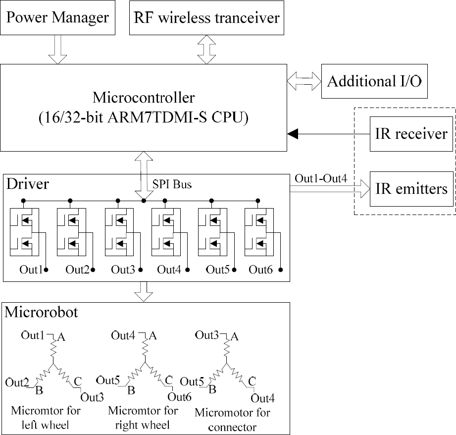
The system architecture of microrobot.
The microrobot is controlled by a microcontroller (LPC2138 from Philips) base on 16/32-bit ARM7TDMI-S CPU, which is characterized by tiny size (LQFP64: 10times10times1.4mm) and low power consumption (working mode: about 10mA at 10MHz). Other important characters are its high processing power (60 MHz maximum CPU clock), large buffer size (32 kB static RAM and 512 kB flash program memory) and abundant peripherals (including 10-bit ADC, 32-bit timers, PWM, SPI, I2C and so on). The user can also download and update the control program of the microrobot by its In-System Programming (ISP) and In-Application Programming (IAP).
Electromagnetic Micromotor Driver
According to the mechanical structure of the microrobot, it can be seen that its locomotion control is directly equal to control of its electromagnetic micromotors. As the three electromagnetic micromotors for two standard wheels and connector need to be driven respectively, this means needing nine half bridge drivers. To reduce the volume of driver circuit, the chip (ATA6836 from Atmel, QFN24: 5times5mm) integrating six independent half-bridge drivers is chosen to drive the microrobot. By using its six half-bridge drivers crosswise, only one chip is enough. As shown in Fig.7, half-bridge drivers 1, 2, 3 are used to drive the micromotor for left wheel. Half-bridge drivers 4, 5, 6 are used to drive the micromotor for right wheel, and the micromotor for connecter open/close is driven by half-bridge drivers 3, 4 and 5. Though half-bridge drivers 4 and 5 are shared, the locomotion control of the right wheel and connecter open/close do not affect each other. To improve the positional accuracy of the microrobot, 2–3 phases conducted approach (3-3 PCA) for the micromotor is adopted, which can realize 12 steps rotation in 360°electrical angle (i.e. 48 steps in 360°mechanical angle) (Li, Z. B., et al., 2007). Since the distance between two standard wheels is 13mm and their diameter is 10mm, the microrobot has positional accuracy of 0.65mm (πx10mm/48) for translational movement and 5.7° (360°x10/48times13)) for steering movement in situ. Such accuracy is high enough to satisfy the requirement of autonomous docking.
Infrared Sensors
The infrared sensors for the microrobot are mainly used for two purposes, one is to perceive the surrounding environment (such as obstacles); the other is to guide them to align each other by detecting IR intensity during a docking action. There are four Φ1.8mm focused IR emitters (BPW17N from Vishay) with the half-angle of 12° and a Φ5mm IR receiver (SFH203P from OSRAM) with the half-angle of 75°. The four IR emitters are placed at the microrobot in four different directions at 90° interval, and the IR receiver are set at its center of rotation, as shown in Fig. 8. The IR emitter has a small effective radiation range of 0–20°, which is beneficial to improve the reliability of docking. Though the half-angle of the IR receiver is only 75°, its conversion ratio is still up to 40% when the incident angle of its receiving IR light is equal to 90°. So it can be used as omni-directional receiver on the plane to perceive the IR light from all directions effectively. Thus, the surrounding environment of the microrobot can be divided into eight different districts, and the microrobot can recognize its position and orientation relative to adjacent one by receiving the light of the four IR emitters of its adjacent one.

Arrangement of IR sensors.
In the IR sensorial system, four IR emitters are respectively driven by Half-bridge drivers 1, 2, 3 and 4 with the driving current of 8mA, the output voltage of IR receiver is converted by 10-bits ADC in microcontroller. The fitted curve of the distance between the IR emitter and receiver versus the received IR intensity (expressed by ADC digital value) is shown in Fig. 9. It can be seen that the intensity of IR light can be well measured in the 25mm–150mm range.

Intensity curve of IR sensors.
To realize communication relay, a RF wireless transceiver (Nordic nRF24L01) is chosen by us. It is a single chip radio transceiver for the world wide 2.4 − 2.5 GHz ISM band with very low current consumption (only 9.0mA at an output power of −6dBm and 12.3mA in RX mode). It has 125 frequency channels, and its data rate on the air can be up to 2Mbps. The size of the wireless transceiver developed by us is 15mmx10mmx2mm (include antenna), as shown in Fig. 10. Its communication distance in open field can be up to 20m–40m. Thus, the distributed mobile microrobots can build up a mobile ad-hoc wireless network (Nguyen, H. G., et al., 2003), so as to prolong the whole communication distance more in multi-hop way.

Wireless transceiver.
Currently, two Li-ion rechargeable button cells (LIR2450-2, 120mAh, 3.6volts/chip) connected in parallel are used as the supply power of the microrobot due to its appropriate volume, large capacity and high discharged current. The power manager has two main functions, one is to produce different supply voltage for the electronic parts of above whole electrical system; the other is to estimate residual capacity of the button cells.
The microcontroller, electromagnetic micromotor driver, infrared sensors and power manager are integrated into a main control board. The basic microrobot with main control board, wireless transceiver and two Li-ion rechargeable button cells is shown in Fig. 11. Thereinto, the button cells are set between the main control board and the chassis of the microrobot; the wireless transceiver is plugged into the main control board, and meanwhile a certain gap between them is kept so as to prevent it from blocking the received IR light. The mass of the basic microrobot is 22.4g, and its size (not including the protuberant parts of connector and wireless transceiver) is 28mmx28mmx30mm. The microrobot can be up to a maximum speed of 13cm/s on the smooth surface, and has a movement range of 70—80m on a battery charge.
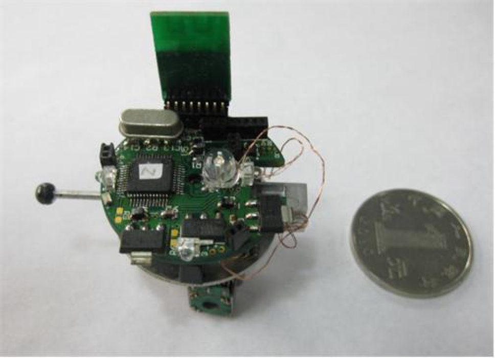
Photograph of basic microrobot with a 22mm coin.
Autonomous docking is an essential capability for self-reconfigurable robots. There are various methods for measuring their relative position/orientation, such as infrared (Fukuda, T. & Nakagawa, S., 1998; Yim, M., et al., 2002; Rubenstein, M., et al., 2004), ultrasonic (Hensinger, D. M., et al., 2002; Wang, W., et al., 2010) or microcamera (Bererton, C. & Khosla, P. K., 2001; Gross, R., et al., 2006; Murata, S., et al., 2007; Zhong M., et al., 2008). As both ultrasonic and microcamera have high power consumption and complicated driving circuit, they are not suitable for microrobot. In contrast, the infrared sensor has the advantages of easy control and low power consumption, and it also has small volume, low cost and high accuracy, so it fits better with the microrobot. In the section, a simple autonomous docking approach based on infrared sensors is presented, the principle of which is illustrated by the following five phases, including search, alignment, approach, insertion and retry. For example, the initial status of R1 (object unit) and R2 (relay unit) is shown in Fig. 12(a).
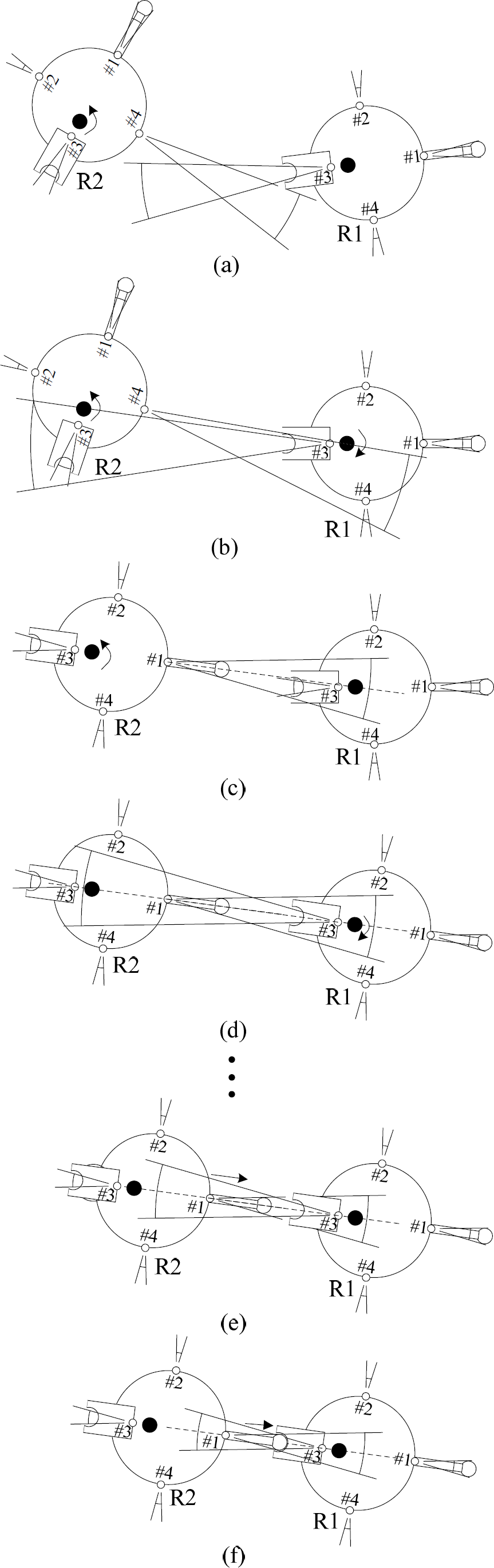
Process of docking between two microrobots.
Search: Let R2 steer ±45°in situ to search R1, until R1 receives the signal from any one of four IR emitters of R2. After that R1 also does in the same way to search R2. As shown in Fig. 12(b), R1 searches the signal from the IR emitter #4 of R2, and R2 searches the signal from the IR emitter #3 of R1. This is because that the initial relative position and orientation between R1 and R2 are unknown when docking begins and the IR emitters have also beam angle, it is possible that they can not receive the signal from each other. Therefore, the search strategy above is adopted to solve the problem.
Alignment: Adjust the orientation of R2 in situ until R1 receive the greatest IR intensity from IR emitter #1 of R2, as show in Fig. 12(c). Next, adjust the orientation of R1 in situ until R2 receive the greatest IR intensity form IR emitter #3 of R1, as shown in Fig. 12(d). At the time, the male connector of R2 has aimed at the female connector of R1.
Approach: Let R2 move straight a designing distance (S d ) toward R1 and then stop to go to alignment phase to check alignment alternatively, until the measured IR intensity is less than the preset threshold (P) which means the male connector of R2 has approached the female connector of R1 to a default minimum distance, as shown in Fig. 12(e).
Insertion: The R2 and R1 move straight toward each other at the same time, so as to make the male connector of R2 plug in the female connector of R1, as shown in Fig. 12(f). Meanwhile, judge whether the insertion action is completed successfully by detecting the change of the conduct status between the cover and base of the female connector of R1. If the insertion is successful, the female connector of R1 is closed by changing the orientation of its latch.
Retry: If the insertion is failed, the R2 will move backwards a fixed distance (S r ) after a timeout (T r ) occurs, and then return to alignment phase and try alignment and docking again. If three retries have been done, the docking procedure will be considered failed. Since the micromotors employ open-loop control and the movement of microrobot may be influenced by some uncertain factors, e.g. assembly error and platform smoothness, it is difficult for R2 to realize ideal translational movement in the process of approaching R1. The longer R2 moves, the larger the movement error is. However, a shorter movement distance will increase the adjustment times and whole time consumption, thus causing low docking efficiency. Therefore, a motion planning method is necessary.
Two principles are taken into account in the motion planning. First, the movement error of the microrobot has a direct relationship with its movement distance. Second, if the microrobot moves the same distance in different area and generates the same movement error, the adjusted angle in the areas further from the target position will be larger than that in nearer areas. Therefore, the closer the microrobot is to the target position, the shorter the designing movement distances should be. That is to say that the microrobot can move longer in the areas further from the target position, while shorter in nearer area.
As shown in Fig. 13, according to the distances between the microrobot and target position, the designing movement distances (S
d
) can be presented as:


The model of motion planning.
Where L is the distance between IR receiver of R2 and IR emitter #3 of R1 in the process of R2 approaching R1, S
c
is the allowed shortest distance between them which occurs at the moment that the male connector of R2 just contacts the female connector of R1, i.e. S
c
= 42mm (referring to Fig. 8). K is the adjustable proportion coefficient. The range of K can be defined as:
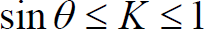
Where θ is the half-angle of IR emitter #3 of R2, i.e. θ = 12°. With K = sinθ, the model of motion planning is based on the worst condition, that is to say, it is impossible for R2 to move out of the half-angle radiation range of IR emitter #3 of R1 even if it moves along shortest direction. With K = 1, the model of motion planning is based on the ideal condition, that is to say, R2 move straight toward R1 without any deviation until the male connector of R2 plugs in the female connector of R1. In practical docking, according to the linearity of translational movement of the microrobot, the lager proportional coefficient should be adopted so as to improve the docking efficiency as much as possible.
Docking Experiment
With the following initialized parameter: K = 0.65, S c = 42mm, S r = 30mm, P = 315 and T r = 5s, the proposed docking procedures have been executed on an even surface with one object unit (R1) and one relay unit (R2), to verify the autonomous docking methods above. Fig. 14(a-c) shows the process that R2 and R1 look for each other in situ. Next, R2 and R1 align each other, as shown in Fig. 14(d-e). Fig. 14(f-k) shows the process that R2 approaches R1 by adopting the motion planning method above, in which three adjustments are made. Finally, the two units move straight toward each other simultaneously, and are docked together, as shown in Fig.14 (1). Fig.15 shows the movement trajectory that R2 approaches R1 in the docking, and the filled circles denote their centers of rotation and the solid lines denote their orientations. Since R1 and R2 cannot recognize its own position and orientation precisely in the process of docking, these parameters are measured by a global camera in experiment.

Experimental process of an autonomous docking.
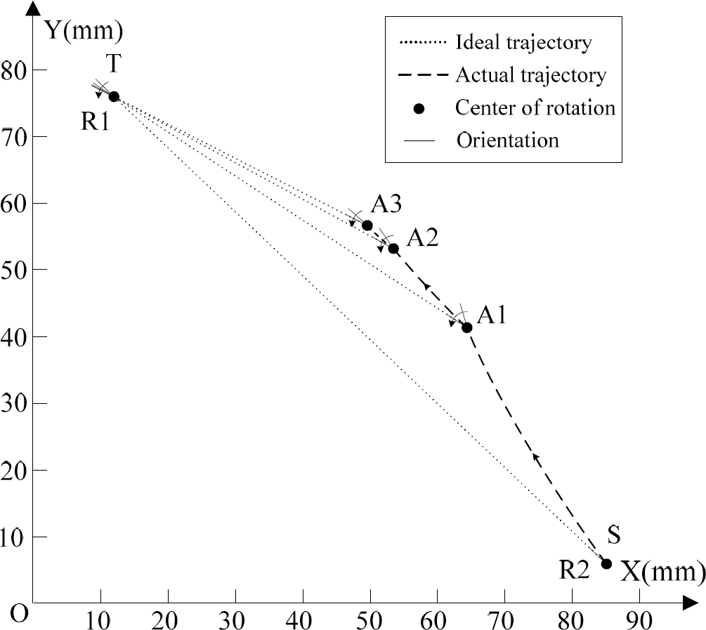
Movement trajectory in the process of approach.
The movement trajectory is divided into three sectors by three adjustment points (A1, A2 and A3). It can be seen that the longer the movement distance of R2 is, the larger its accumulated deviation error is. The adjustment points become denser and denser (from the start point S to the final target point T), because the distance between R1 and R2 and the permitted deviation error are reduced gradually. It is obvious that more adjustments can reduce the nonlinearity of the trajectory, but also increase the whole time consuming. Therefore, the key to improve the docking efficiency is to choose a reasonable proportion coefficient, which can be found by testing the linearity of translational movement of the microrobot. In the microrobtic system, the proportion coefficient is set as 0.65.
Various initial positions and orientations relative to each other were tested in the range of 45mm–150mm and 0–360°, and docking was successful for all thirty trials. Each successful experiment without retry lasts about 10–35 seconds depending on the initial relative positions and orientations between the two units. Thereinto, a retry happened in a trial because of failed alignment and took 16 seconds, which was caused by mutation of ambient light intensity in the process of approach. The experimental results show that the proposed docking method has short time consuming (less than 1 minute) and high reliability. The main reason lies in adopting the methods of centering alignment and motion planning. However, the approach does not fit with docking more robots continually, and more complicated motion planning algorithm needs to be developed based on current hardware configuration in the future.
To demonstrate the improved ability of whole microrobotic system and explore application, five basic microrobot prototypes (R1, R2, R3, R4 and R5) and a specialized microcamera are developed so that the microrobots can carry out large-range vision-based surveillance cooperatively by power and communication relays, as shown in Fig. 16. The microrobots can be controlled manually or automatically by wireless through a visual control panel of host computer, and the acquired images can be also displayed on it.
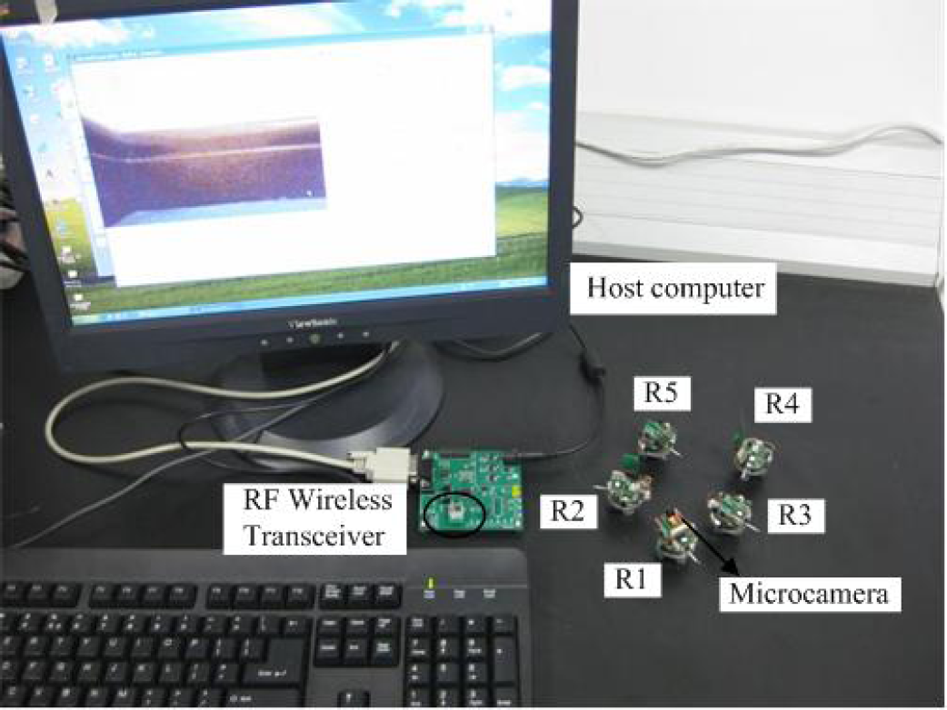
Experiment platform for control of multiple microrobots
The microcamera is a low voltage 1/6 inch CMOS image sensor (OV7670 from Omnivision) with 300K pixels. To improve image acquisition rate and reduce the system overhead, a camera control processor (MV3018 from MtekVision) with 1Mbit embedded memory and hardware based real-time JPEG compression and decompression, is chosen to control it wholly. Thus, the microcontroller of microrobot can directly gain the compressed images through data bus interface of MV3018. The size of the microcamera developed by us is 20mmx20mmx5mm, and its mass is 2.9g, as shown in Fig. 17. With 3.3v supply voltage, its current consumption is 56 mA in continuous image acquisition mode (image size: 640times480, transmission rate : 3fps), and 200uA in standy mode.

Microcamera.
However, with the microcamera mounted on the basic microrobot, its maximum movement distance and running time will be both decreased because of the additional power consumption, which accounts for about 60% of that of the microrobot. This means that the detection range of single microrobot with microcamera is very limited. To enlarge its detection range, some basic modules can be used as power relay units to pull it to further places. Thus, most of its energy can be also used for microcamera.
In the designed experiment, R1 carries microcamera and performs vision-based surveillance along the wall of the whole room (14mx12m), and the other four basic modules are used as power and communication relay units, as shown in Fig. 18. Due to limited wireless communication distance, if R1 fulfills the task independently, it will lose contact with the host computer when it moves to point E. In addition, the furthest place is at point F which it can arrive at because of the lager energy consumption from the microcamera. Under this condition, the following cooperative strategy can be adopted.

Cooperation of multiple microrobots by power and communication relays.
Firstly, R3, R4 and R5 are deployed at the corner B, C and D respectively, and R2 is connected with R1 manually and pull it to corner B, as shown in Fig. 18(a). The five distributed wireless microrobot form a multi-hop Ad-hoc networks. Next, when R2 and R1 arrive at corner B, R2 is separated from R1 automatically and used as a communication relay, and then R3 and R1 link together autonomously, as shown in Fig. 18(b). After R1 passes through point E, it can transmit its acquired images to the host computer by wireless in the way of multi-hop. To enable R1 to transmit its acquired images to host computer at the fastest speed and least power consumption, the shortest routing between and R1 and host computer should be adopted, i.e. R1→R2→Host computer. In the same way, R1 goes through corner C and D in sequence, and finally arrives at to the start point A by cooperation of relay units R3, R4 and R5, as shown in Fig. 18(c-d). After that, all the outer relay units return (R2, R3 and R4) the start point A along the shortest path.
The whole process above is done automatically. During the locomotion, each microrobot can follow walls, avoid obstacle and steer by controlling the distance between its IR emitters and the wall. The real-time shortest routing between R1 and host computer can be founded quickly by adopting AODV routing algorithm with energy saving. Fig. 19 shows the relay experimental scenes happening at corner C, in which first R3 stops when it finds R4, next R1 and R3 are separated from each other automatically, after that R4 and R1 link together by adopting the docking method above and move toward next corner D. Therefore, by the power and communication relays above, the detection range of single mobile microrobot can be enlarged.

Relay experimental scenes happening at corner C.
This paper presents a modular mobile self-reconfigurable microrobot actuated by two different sizes of electromagnetic micromotors based on MEMS technology. Considering that the available volume is limited, and the power consumption should be reduced as much as possible, the electrical system of the microrobot is designed in modularity and integrated, including microcontroller base on ARM7, electromagnetic micromotor driver, IR sensors, wireless transceiver and power management. Due to scaling effects, a passive universal connector with automatic disconnecting/connecting function is designed, and a simple autonomous docking method based on infrared sensors is developed. Since the methods of centering alignment and motion planning are adopted, the presented docking method has high efficiency and reliability. In the microrobotic system, each unit can be used as power and communication relay unit. Thus they can collaborate to enlarge their whole surveillance range. Finally, by adopting the novel cooperative method, the improved ability is also demonstrated in a designed relay experiment.
Footnotes
7. Acknowledgements
This work is supported by Hi-Tech Research and Development Program (“863”Program) of China (No. 2007AA04Z340).