
Abstract
Micro mobile robots (MMRs) can operate in rugged, narrow or dangerous regions; thus, they are widely used in numerous areas including surveillance, rescue and exploration. In urban environments, stairs are common obstacles, ones that such robots find difficult to manoeuvre over. The authors analysed the research status of MMRs, particularly in terms of difficulties when performing stair climbing and present a novel type of MMR called the micro flip robot (MFRobot). A support arm subassembly was added to the centre of a wheeled chassis; using this structure, the MFRobot can climb stairs when a flipping mode is utilized. Based on this structure, the authors established a kinematic model of the stair-climbing process and analysed the force conditions for the key status, contributing to the existing knowledge of robot design. An MFRobot prototype was produced and the stair-climbing experiments, as well as experiments on manoeuvring through rubble regions and slope surfaces, were conducted. The results show that the MFRobot can rapidly climb common stairs and can easily manoeuvre through a rubble region. The maximum slope angle the robot can climb was shown to be about 35° for concrete and wooden slope surfaces. In the case where the robot needed to be equipped with sensors, particularly a camera, the camera was equipped on the support arm of robot. The MFRobot prototype weighs 2.5 kg and is easily transportable. This structure can resolve contradictions between portability and performance in terms of overcoming obstacles; in addition, operational effectiveness can be improved using this structure.
1. Introduction
Micro mobile robots (MMRs) can operate in rugged, narrow and dangerous regions and have therefore been widely used in numerous contexts including surveillance, rescue, and exploration [1]. The main operational mode of these robots is that they are placed or thrown near targets and then move into the specific work area via remote control [2]. Hence, portability and performance in terms of overcoming obstacles are both important; this presents numerous difficulties in structure design.
A two-wheeled robot, Scout and its launch vehicle, Ranger, were developed at the University of Minnesota [3]. Scout is smart and Ranger is large; the launch vehicle can carry 10 Scout robots. Their work area can be expanded to 20 km and the vehicles can be launched over 30 m. O'Halloran of Carnegie Mellon University developed a type of two-wheeled robot [4] that can endure the large impacts of being dropped. The main shock absorption mechanisms are inflatable tires and a suspension chassis system. The Beijing Institute of Technology has developed a Third Generation two-wheeled surveillance robot. This robot can be equipped with a camera, microphone, thermometer, proximity sensor and other sensors, and uses inflatable tires that can absorb impacts omnidirectionally [5]. The National University of Defense Technology, Beihang University and the Nanjing University of Aeronautics and Astronautics have conducted research on two-wheeled robots and deformable spherical robots [6–8]. These robots are typically similar in shape to dumbbells, with one tire on each side providing movement. Such robots usually weigh less than 1 kg and can endure large impacts; however, their mobility and performance in terms of overcoming obstacles are weak. Their deployment methods always consist of being thrown by hand or being launched by an ejection device.
Another type of MMR has a common wheeled or tracked chassis, weighs no more than 5 kg and can be thrown short distances. The US-based company iRobot has developed an MMR called 110 FirstLook [9]. This robot has a tracked chassis and two arms are equipped in front of the chassis to aid in overcoming obstacles. Carnegie Mellon University, together with the US Naval Research Laboratory, developed the Dragon Runner Robot system, which consists of a micro ground vehicle, operational controller and user interface [10,11]; the system can be equipped with a microphone, camera and other devices.
The above-motioned robots are all portable and certain robots have some degree of obstacle-overcoming capability; however, none can overcome large obstacles such as stairs or crushed stone. However, in urban environments, stairs are common barriers and robots must often perform recon on different types of floors [12]. Tracked robots can climb stairs consecutively if the size of the tracks on the ground is sufficiently long, as is the case with, for example, the 510 PackBot [13], developed in the US, ResQuake developed in Iran [14] and the RAPOSA robot developed in Portugal [15]. These robots are relatively large and heavy, however, and it remains difficult for small tracked robots to successfully navigate stairs.
In this paper, a micro flip robot (MFRobot) is proposed, the tire chassis of which can climb stairs using support arms connected to the centre of the chassis. This robot weighs 2.5 kg and is 216 × 88 × 348 mm (width, height and length), with the support arm component being 400 mm in length. The tire diameter is larger than the thickness of the chassis. As a result of this feature, the robot's front tires can firmly stick onto the horizontal plane of stairs when the chassis flips and the tires are unlikely to slide down the stairs. This structure concept can resolve the contradiction between a robot's performance in overcoming obstacles and their weight and size.
This paper is organized as follows. Section 2 describes the architecture and operating principle of the MFRobot. In section 3, the key status of the stair-climbing process is discussed and the authors establish the kinematic model. Furthermore, the key critical dimensions are designed and their influence on the robot's performance is discussed. Section 4 performs the stability analysis of climbing stairs based on a force analysis. Section 5 presents a prototype and the experimental results. In Section 6, the authors draw conclusions and note directions for further work.
2. MFRobot Architecture
2.1. Mechanism
The main body of the MFRobot consists of the tire chassis and the support arm subassembly, as shown in Figure 1(a), in which the front and back wheels are demarcated because the chassis can flip over. The two support arms are equipped on opposite sides of the chassis and are connected by a rotating shaft at the centre of the chassis. The link bar is used to improve the rigidity of the arm subassembly.

MFRobot mechanism diagram
When the robot climbs stairs using the flipping motion, the wheels sticking to the step's horizontal plane must be braking or slowly rotating forward, ensuring that the robot does not slide down from the upper step. The front and back wheels will stick to the steps in an alternating manner; therefore, the two types of wheels must be driving wheels. The front and back wheels on the left side are powered by one motor. The torque and rotation are transmitted by a synchronous belt and synchronous pulleys. The right and left sides are symmetric, as shown in Figure 1(b). The rotating motor is a steering engine with “endless turn mode” and “joint mode”. The motor's power output must be substantial to provide the large torque necessary when the chassis flips; moreover, in “joint mode”, the angle position of the support arms can be easily controlled.
2.2. Locomotion concepts
In the ground-moving state, the MFRobot moves in the same manner as other wheeled chasses, such as Dragon Runner, running on flat ground, slopes or rugged regions.
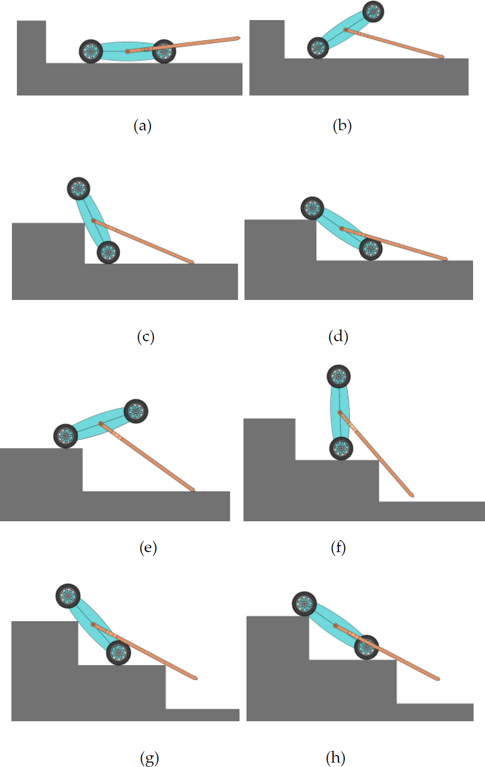
The stair-climbing movements using the flip mode are shown in Figure 2. First, the robot approaches the stair; then, the support arms rotate around the axis at the chassis centre, as shown in Figure 2(a). The arms continue to rotate even if it touches ground and the entire chassis is lifted up using the support of the ground, as shown in Figure 2(b). The arms continue to rotate as the chassis is lifted up; if the centre of gravity moves ahead of the first graze of the tire, the chassis will lean against the step, as shown in Figure 2(c). If the arms continue to rotate, the chassis will be forced to slide down to the step edge until the tires touch the horizontal plane, as shown in Figure 2(d). Until this state, the chassis will flip once and the tire will stick on the upper step. The locomotion that follows is similar to the previous process. Figure 2(e) to Figure 2(h) show the process of the chassis' second turn. To climb n steps, the robot chassis must rotate and flip n+1 times; in other words, it has to rotate (n+1)/2 times.
MFRobot stair-climbing locomotion concepts
3. Kinematic Modelling and Analysis
Assuming that the dimensions of the steps are equal, the process of climbing stairs can be viewed as repeatedly climbing one step. In this locomotion, there are two types of driving pairs. The first type is rotation between the support arms and chassis, while the other type is rotation between the wheels and the chassis, in which the first pair requires substantial torque and is the key driving pair. Taking a particular status as the initial state, the authors established a stair-climbing kinematics model and analysed the force stations of key states. Based on this model, the authors noted the variations in position and gestures of the chassis and the driving torque, taking the support arm angle gestures as independent variables. Furthermore, key dimensions were designed and their effects on the robot's performance are discussed.
3.1. Kinematics model
Assuming that the tires' rotational speed is zero (or that the tires brake) during the stair-climbing process and assuming that the tires do not slip on the step's surface, the chassis' position and gesture can be determined according to the angle between the arms and the chassis. Figure 3 shows a typical status. At this status, the front tires contact the upper step surface, the chassis contacts the upper step edge and the support arms resist the lower step edge. The figure is drawn in two dimensions and the chassis' outline is drawn using contour lines.

Initial status of the stair-climbing process
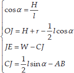
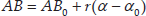
The symbols in Figure 3 are as follows: front and rear wheelbase (l); length of support arms (lt); wheel radius (r); chassis' rotational centre (O); front wheel rotational centre (O1); rear wheel rotational centre (O2); contact point of front wheel and the upper step surface (A); upper step edge (B); contact point of rear wheel and the lower step surface (K);lower step surface edge (E). The robot's position and gesture can be described by the following three angles: the angle from the arm to the chassis (δ); the angle from the step's vertical plane to the chassis (α);the angle from the arm to the step's horizontal plane (β), in which δ is an independent variable and α and β are dependent variables. The relationships among geometric parameters in this status can be described as follows:
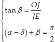
The parameters in Equation (1) are determined by Equation (2).
If the support arm begins to rotate around the chassis' centre, the chassis will be lifted up by the arm; this status is shown in Figure 4. In this status, Equations (1) and (2) remain valid and there is a complementary expression for

Status of chassis being lifted
When the support arm reaches the step edge, the arm continues to rotate and rests on the step's horizontal surface, as shown in Figure 5 and Figure 6. In Figure 5, the arm's end reaches the step edge; at this status, Equations (1), (2) and (3) are valid, and there is the following complementary expression for

The support arm reaching the step's edge
The support arm resting on the step's horizontal surface

At the status shown in Figure 6, Equation (3) is valid and the relationships for other parameters are shown in Equation (5). Some of the parameters are determined by Equation (6):

When the chassis is perpendicular to the step's horizontal surface, the arm continues to rotate and the chassis is forced to lean against the upper step's edge, as shown in Figure 7 and Figure 8. In the status shown in Figure 7, Equations (3), (5) and (6) are valid, and the following complementary condition holds:

The chassis is perpendicular to the step's horizontal surface

The chassis leans on the upper step's edge
At the status shown in Figure 8, α3 and β3 are determined by the step dimensions and the previous status. These expressions are given by Equations (7) and (8):


Following the status shown in Figure 8, the arm continues to rotate until it touches the step edge, as shown in Figure 9. The arm continues to rotate and the lower wheels are forced to slip backward as the chassis rests on the step edge, as shown in Figure 10. This progress will be sustained until the upper wheels touch the step's horizontal surface, as shown in Figure 3. At the status shown in Figure 9, Equation (1) is valid, with complementary equations shown in Equation (9).
The arm touches the step's edge

The lower wheels slip backward along the step's surface

At the status shown in Figure 10, Equation (1) is valid, with complementary equations shown in Equation (10).

Using Equation (1)~Equation (10), the robot's position
3.2. Critical dimensions
At the status shown in Figure 3,

If the step dimensions are given, the longer l is, the greater

At the status shown in Figure 7, the rotating arm must steadily rest on the step's surface; therefore, arm length lt should be shorter than

Support arm length lt ranges

In Equation (13),

Equation (11)~Equation (14) reflect the requirements of l and lt for climbing a given step. On the other hand, the maximum height of the step that the robot must climb is an important parameter. Supposing that l, lt, r and d are given, the maximum value of H is constrained.
From Equation (12), we find that H is limited by l and W:

The chassis is shocked when climbing the stairs, corresponding to the states in Figure 10, Figure 3 and Figure 4. Therefore, it is possible for the front wheels to slip backward to some extent. Thus, the distance

Translating the equation above as Equation (16), it can be observed that H exhibits a nonlinear relationship with r, d and l.

Moreover, H is also limited by arm length lt. Figure 11 shows the condition for the arms in order to not make contact with the step's edge:
The above equation can be written as:
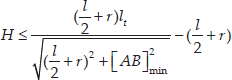
Equations (15), (16), (17) are restricting conditions of H and in practice should be simultaneously satisfied.
Define the step dimensions H = 150 mm and W = 300 mm. These dimensions conform to GB_17888.3-1999, Permanent means of access to machines and industrial plants – Part 3: stairways, stepladders and guide-rails. According to the critical dimensions in Equations (13)~(16), the authors set the critical dimensions as follows:
d = 54 mm, r = 44 mm, l = 260 mm, and lt = 410 mm.
According to the kinematics model in Equations (1)~(10), variations in α and β can be solved as the support arm rotates 2 π rad or when δ changes from −0.1 rad to 3.04 rad, as shown in Figure 12. When δ equals 2.5 rad, the chassis is perpendicular to the step surface. The arms continue to rotate and the chassis subsequently falls onto the step edge; thus, the two angles change sharply. This process is shown in Figure 12.

Chassis gesture angle as a function of arm angle
4. Stability of Climbing Stairs
4.1. Force analysis
There are two types of driving torques in the stair-climbing process: the wheels' braking torque (

Force analysis during stair climbing
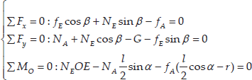
Some of the parameters in Equation (18) follow the relationships shown in Equation (19).

In Equation (19), μ1 is the friction coefficient between the wheels and the step, and μ2 is the friction coefficient between the support arms and the step; fA, NA and NE are three unknown parameters that can be solved using Equations (18) and (19). In other statuses, the force conditions are similar to that shown in Figure 13. By establishing the force balance equations on the X - and Y -axes and the torque balance equations around O, we can calculate the parameters according to the geometrical relationships and resolve driving torque T and braking torque
The robot is set as weighing 5 kg; this parameter is one of the design bases for the power system and there is some redundancy. According to the results of the kinematics model and force analysis equations, driving torque T and braking torque

Driving torque T vibration as a function of arm angle

Braking torque
4.2. Stability analysis
The stability condition for climbing the stairs is the friction force f
A
pointing toward the front being larger than the maximum friction force

In Equation (20), μ is the friction coefficient and fA and NA vary according to δ.
The friction coefficient between the front wheel and the road falls in the range (0.37~0.78) and in this paper, μ is approximately 0.6. Taking the arm angle δ as the independent variable, the variations in fA and

Friction force vibrations as a function of arm angle
Figure 16 shows that fA is larger than
The results of a comparison of the stabilities of different friction coefficients in the range (0.4~0.8) are shown in Figure 17.
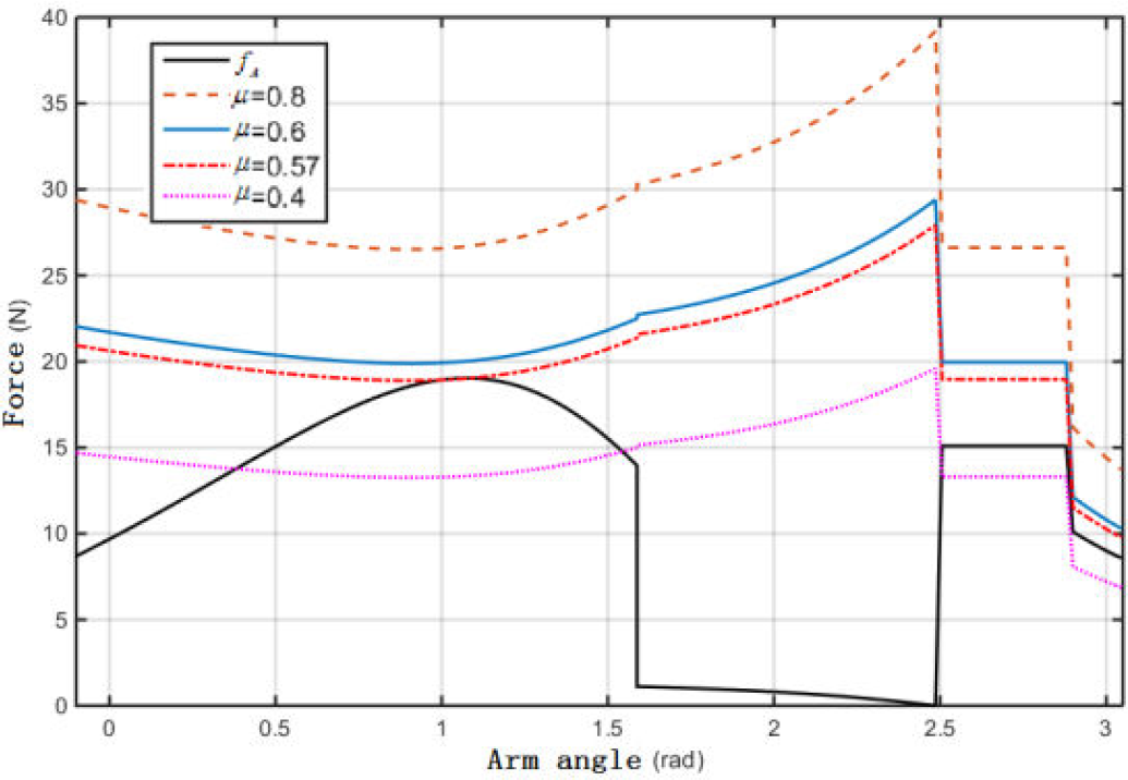
Stabilities of different friction coefficients
Figure 17 shows that the friction coefficient increases stability and thus represents a critical factor. If the coefficient is less than 0.57, the front wheel will slide down from the upper step's surface.
In addition to the friction coefficient, stability also exhibits a relationship with wheel radius r, chassis thickness d, rear wheelbase l, support arm length lt, the position of the centre of gravity, etc. Some of these factors exhibit nonlinear relationships with stability and are coupled; therefore, it is not appropriate to study the influence of only one factor. In practice, stability can be judged according to Equation (20) by plotting curves of fA and
5. Experiments
5.1. Robot prototype
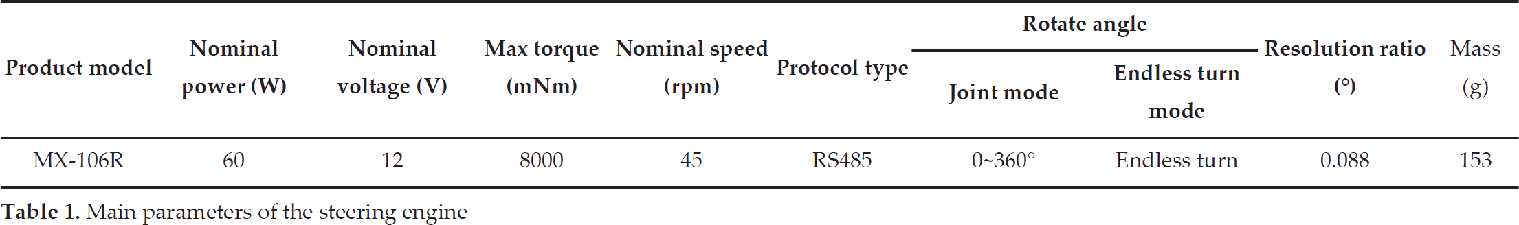
The authors designed the MFRobot prototype as shown in Figure 18. The prototype weighs 2.5 kg, where the chassis is 2.24 kg and the arm components are 0.26 kg. The true dimensions are 216 × 88 × 348 mm (width×height×length) and the arms are 400 × 239 mm (length × width). According to the results of the force analysis, the Dynamixel MX-106 steering engine was selected as the flipping motor. The main parameters of this motor are shown in Table 1. This motor has a large power density and can operate in an endless turn mode and joint mode. In the endless turn mode, the motor can drive the arms to continuously rotate, successively flipping the chassis. In the joint mode, the arms can be conveniently located at any angle position. This prototype is remote controlled because it has to flip over and wires can cause issues during manoeuvring.

MFRobot prototype
Main parameters of the steering engine
5.2. Stair-climbing experiments
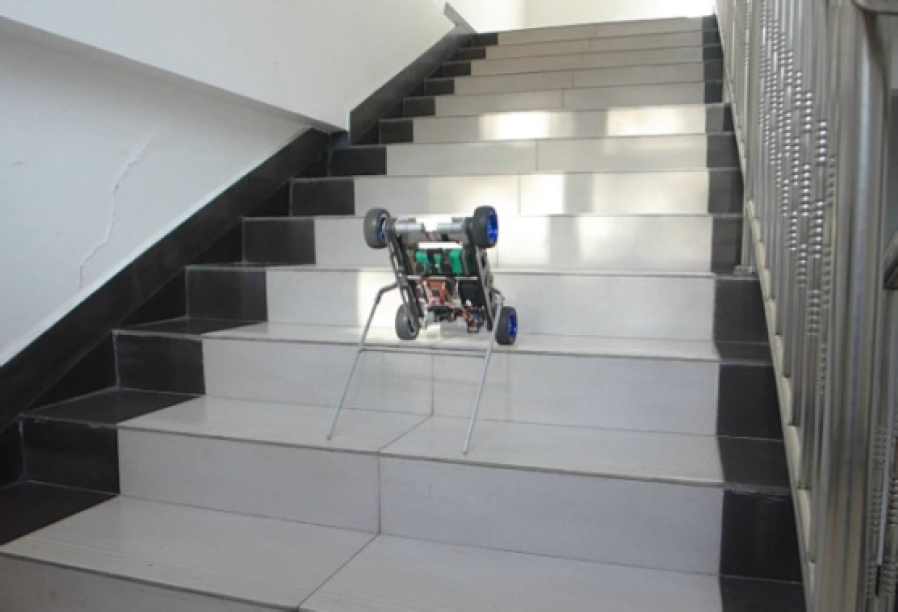
Climbing stairs is the main task of this robot. In this experiment, the step is 150 mm in height and 195 mm in depth. This experiment used four limestone stairs. The robot was set to flipping mode and the arms' rotational speed was set to 20 rpm. The results showed the following: by flipping five times, the robot climbed stairs using four steps and manoeuvred in a stable manner without any slippage. Video screenshots of the robot climbing the first three steps are shown in Figure 19, while the other processes are repeated movements.

Screenshot of the MFRobot climbing a set of stairs
Figures 19(a)~(d) show the process of the rear wheels lying on the first step, in which the edge of the first step is marked in the pictures with a white line for 0 s~1.75 s. Figures 19(e)~(g) show the process of climbing the first step and the front wheels lying on the second step, i.e., 1.75 s~3.33 s. Figures 19(h)~(j) show the process of climbing the second step and the rear wheels lying on the third step, i.e., 3.33 s~4.79 s. Figures 19(k)~(l) show the process of climbing the third step and the front wheels lying on the fourth step, i.e., 4.79 s~6.37 s.
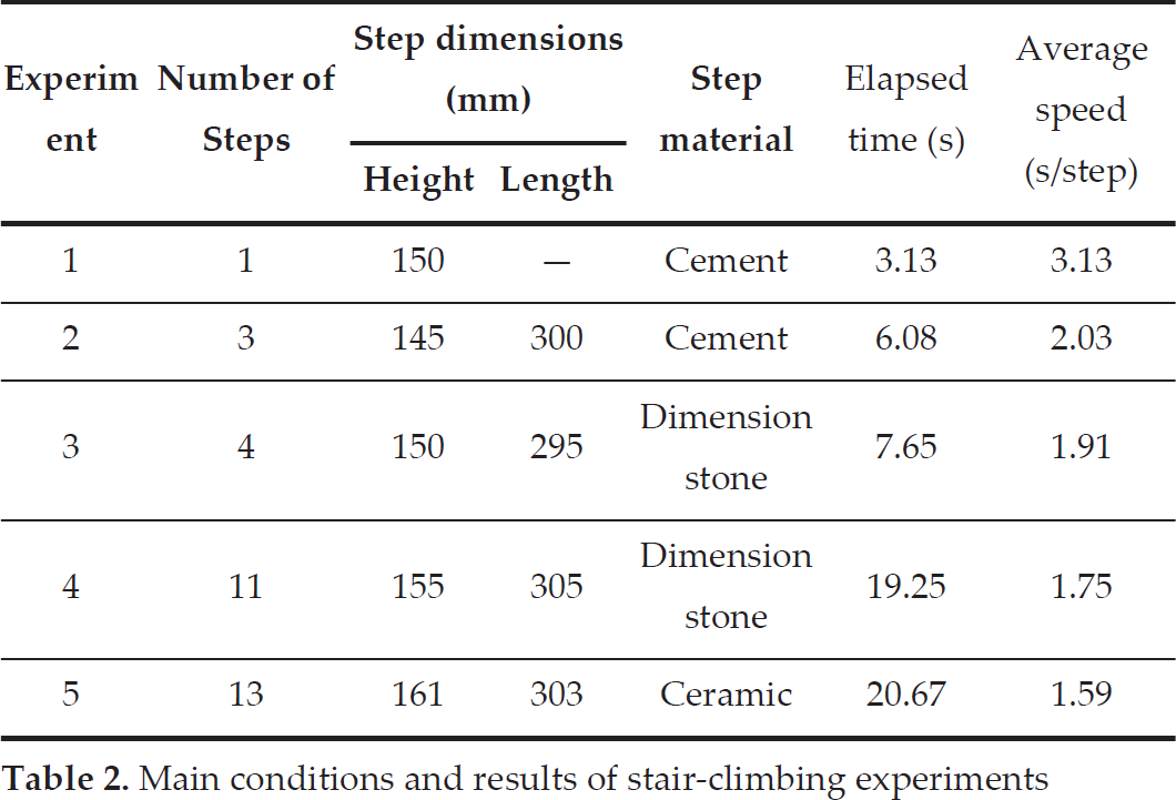
The MFRobot performed 2.5 rotations to climb four steps in 7.65 s and the climbing speed was 1.91 s/step. Various other experiments were conducted and the main experimental conditions and results are shown in Table 2, Figure 20 and Figure 21. In Table 2, one step of the stairs refers to the shoulder. Figure 20 is a screenshot of Experiment 4 and Figure 21 is a screenshot of Experiment 5.

Screenshot of the robot climbing 11 steps
Screenshot of the robot climbing 13 steps
Main conditions and results of stair-climbing experiments
5.3. Rubble region and slope surface experiments
The adhesion force and the ride height are restricted for micro mobile robots; as a result, they can become stuck in rugged regions. Rubble regions are a representative type of rugged region; moreover, they are one of the most difficult barriers to overcome. This MFRobot uses the flipping mode to overcome obstacles; therefore, it can address such issues if it becomes stuck and can manoeuvre across rugged regions by continuously flipping.
The main conditions of the rubble region experiment are as follows: the region is 5 m in length and 2 m in width, the rubble is 32 cm~53 cm in height, and the MFRobot manoeuvres across the rubble. To protect the inner electrical components, the authors added a cover on the top of the robot, increasing the robot's weight to 2.72 kg. The entire process is shown in Figure 22. Figure 22(a) shows the initial position. Figures 22(b)~(d) show the process of the first flip: the chassis is lifted up in Figure 22(b), the robot's centre of gravity moves ahead of the front wheels in Figure 22(c) and the chassis falls onto the ground. Figures 22(e)~(h) are screenshots of the crossing process. Figure 22(i) and Figure 22(j) show the last flip in the rubble region, in which the robot is indicated with a white circle in the figures. Figure 22(k) and Figure 22(l) are screenshots showing the flat region after crossing the rubble. The entire process for overcoming the rubble required 13 seconds and the robot successfully manoeuvred across this region. The robot's movement direction deviated to an extent.

Screenshots showing the robot crossing the rubble region
For the concrete and wooden slope surface, the maximum slope angle the robot can climb is roughly 35°.
5.4. Equipping the camera
The robot flips its body only when climbing stairs and crossing a rubble region. In either case, its support arms do not flip; therefore, in a case where the robot needs to be equipped with sensors, particularly a camera, the camera can be equipped on the support arm of the robot, as shown in Figure23.

Camera can be equipped on the support arm of the robot
6. Conclusions
In this paper, a type of flipping micro-robot structure is presented. The support arm subassembly is designed based on a wheeled chassis; this structure gives the micro mobile robot the ability to climb stairs, resolving the contradictions between a robot's weight and its ability to overcome obstacles.
The stair-climbing process is decomposed into several statuses. A kinematics model is established and the force state is analyzed based on these statuses. Taking the relative angle between the support arm and the chassis as the independent variable, the robot's gesture, position and driving torque can be mathematically described. This work provides theoretical guidance for critical dimensions in the design of major components and provides a basis for dimensions for optimizing and improving the adaptability of robot for climbing stairs of various heights.
An MFRobot prototype was developed and tested for climbing stairs and a sloped surface, as well as for crossing rubble regions. The results show that this robot is able to climb stairs of common dimensions and materials and that it can successfully cross rubble. The maximum slope angle the robot was able to climb was roughly 35° for a concrete and wooden sloped surface. Where the robot needed to be equipped with sensors, specifically a camera, the camera was equipped on the support arm of robot. These results confirm that the structure scheme is feasible and that the prototype is generally rationally designed.
There are several directions for improvement in future work. First, the support arm subassembly should be designed to support plug-and-play modules so that the robot can be thrown into a workspace under numerous conditions. Second, the chassis' anti-impact capacity must be improved for deployment by throwing.
Footnotes
7. Acknowledgements
This work was supported by the Program for Changjiang Scholars and Innovative Research Team in Beijing Institute of Technology under Grant IRT1208.