
Abstract
This paper presents an omni-directional wall-climbing microrobot with magnetic wheels. The integral design with an actuator and adhesive is realized by integrating stators and rotors of an MEMS-based electromagnetic micromotor with a magnetic wheel. The omni-directional wall-climbing mechanism is designed by a set of steering gears and three standard magnetic wheels. The required torque and magnetic force for microrobot movement are derived by its static analysis. The size of the magnetic wheel is optimized, with consideration of its own design constraints, by ANSOFT and Pro/Engineer simulation so as to reduce unnecessary torque consumption under the same designed load. Related experiments demonstrate that the microrobot (diameter: 26mm; height: 16.4; mass: 7.2g; load capacity: 3g) we have developed has a good wall-climbing ability and flexible mobility, and it can perform visual detection in a ferromagnetic environment.
1. Introduction
With the development of MEMS and bionic technologies, the research of wall-climbing microrobots has draw great attention from researchers over the last decade. As a special kind of mobile microrobot, a wall-climbing microrobot can go into limited and complicated three-dimensional spaces which are hazardous or inaccessible to humans, such as gas turbines, narrow pipes etc. To accomplish tasks efficiently, robots must have a small size, strong adhesion, flexible mobility, low power consumption and a high load capacity. Therefore, their locomotion mechanism, actuator and adhesive principle are inevitably different from those of traditional wall-climbing robots of a larger size due to scaling effects and the special work environment.
Current wall-climbing microrobots sized around several cubic centimetres mainly adopt two adhesive principles: magnetic force and synthetic adhesive. Up until now, examples of other adhesion principles, such as suction cups, grasping mechanisms or gripping with a claw, as applied to wall-climbing microrobot with a small volume are rare. Takeda developed a wall-climbing microrobot with two differential magnetic wheels actuated by radial-gap cored electromagnetic micromotors [1]. Fischer developed a foldable magnetic wheeled climbing robot for the inspection of gas turbines and similar environments with very narrow access holes [2]. Rochat developed a cylindrical wall-climbing microrobot with two wheels and magnetic adhesion, which has good mobility and can make the transition to almost any intersecting sheet from 10° to 360° [3]. Aoyama developed a modular microrobot with wall-climbing ability and high mobile accuracy which adopts electromagnetic adhesion and is actuated by a piezoelectric driver [4]. Greuter designed an autonomous microrobot with tread-based locomotion mechanisms and silicone rubber adhesive [5]. Unver designed a sixteen-legged palm-sized wall-climbing microrobot using a flat bulk tacky elastomer adhesive [6]. Daltorio designed a four wheel-legs wall-climbing microrobot using Scotch tape as the foot adhesive [7]. The two adhesion principles listed above have their own advantages and drawbacks. The synthetic adhesive enables the robot to traverse a wide variety of surfaces, but its adhesive ability may be degraded quickly when it is contaminated by dust and dirt. Magnetic adhesion suffers from the major drawback of being only suitable for ferromagnetic structures, but its adhesion force and reliability is superior to other known adhesive principles [8]. In comparison with electromagnets, both permanent magnets and synthetic adhesives have the advantages of a simpler structure and lower energy consumption. Thus, they are more suitable for a wall-climbing microrobot.
Omni-directional wall-climbing robots have also been researched by several groups due to their flexible mobility. Generally, the Mecamun wheel [9-10], the steered standard wheel [11] or the caster wheel [12] has been adopted, and the adhesive principles used by them have mainly involved a suction cup [10-11] or a magnetic force [9-12]. However, they generally have a larger size because of their complicated mechanical structures and because of the scarcity of suitable microactuators with a high torque and a small volume.
In this paper, an original omni-directional wall-climbing microrobot with magnetic wheels directly integrated with electromagnetic micromotors based on MEMS technology is studied. The magnetic element and the wheeled mechanism have been chosen due to their high reliability, low power consumption, simple structure and control, flexible mobility and high efficiency. The remainder of the paper is organized as follows. Section 2 presents the detailed design of microrobot. Section 3 derives the required magnetic force and torque by static analysis. The optimal design of magnetic wheel is given in Section 4. The preliminary experiment is presented in Section 5, which is followed by the conclusion in Section 6.
2. Design of the microrobot
2.1. Electromagnetic micromotor
The microactuator is a crucial part in the design of microrobots, mainly because of the lack of currently available micromotors and the unsatisfying performance of existing ones. Compared with other varieties of micromotors - such as electrostatic, piezoelectric, ultrasonic, pneumatic and shape memory alloy - the electromagnetic micromotor has a larger output torque and a higher efficiency in the same volume [13]. According to the directions of magnetic flux, electromagnetic micromotors can be generally divided into two types: radial flux and axial flux micromotors. Comparing with radial flux micromotors, axial flux motors can improve the efficiency of electromagnetic energy transformation, enlarge the electromagnetic interaction area (the most important parameter for a micromotor) between a rotor and a stator, and shrink the whole volume. Therefore, in this section, an original axial flux millimetre-sized electromagnetic micromotor with the structure of one rotor, two stators and axial flux is developed, as shown in Fig. 1(a).

Electromagnetic micromotor

Fabrication process of the winding of the stator (first layer)
The winding of the stator is fabricated on a ferrite substrate with non-silicon microfabrication techniques. The winding is composed of multiple layers of slotless concentrated planar coils, and is embedded with magnetic cores of a NiFe alloy in order to increase the output torque of the micromotor, as shown in Fig. 1(b). In addition, Al2O3 is deposited as isolation layers between the coils so as to improve the heat-resistance performance of the winding. The fabrication process of the first layer of the stator‘s winding is shown in Fig. 2, including a photolithography process based on UV-LIGA, electroplating, etching, sputtering, milling and polishing. The fabrication process of other layers of the winding is similar to that of the first layer of the stator‘s winding. The difficulty of fabricating the winding of the stator will increase with the number of layers. The rotor is made of a magnetic permeable material layer (DQ117G-35, a kind of silicon steel sheet) covered with two layers of Sm2Co17 permanent magnetic alloy, as shown in Fig. 1(c).
The winding of the stator is composed of 6 layers of coils, 144 turns and 6 pairs at a combined size of 6.8mm×6.8mm×0.7mm (length, width and height). The rotor has 4 pairs of magnetic poles and its thickness is 0.55mm while diameter is 6.6mm. The distance between the rotor and the stator is 0.1mm. The total size of a single micromotor is 6.8mm×7.8mm×3.9mm, its mass is 0.8g and its maximum speed and output torque can be up to 18000 rpm and 0.58mNm with a supply current of 100mA.
2.2. Mechanical structure
The microrobot is composed of three standard magnetic wheels which are separated at a distance and connected to each other by a set of gears (a small gear and three big gears). The CAD model of microrobot is shown in Fig. 3. Each magnetic wheel is made of two round ferromagnetic pieces stuck onto each side – symmetrical to one another – of a ring permanent magnet with axial flux. To decrease the torque loss caused by intermediate mechanical transmissions and also to improve the driving efficiency, the magnetic wheel is directly actuated by a micromotor. In addition, the two stators and one rotor of the micromotor are directly mounted on one side of the wheel carrier as so to reduce the whole size of the standard magnetic wheel. Although a similar magnetic wheel has been reported in our previous paper [14], the present wheel is mainly used to limit the slip effect of the mobile microrobot for microassembly and thus improve its positioning precision on the plane. The steering mechanism of the microrobot is designed by using a set of gears which are mounted at the bottom of its round chassis. A micromotor for steering movement is mounted at the top of the chassis and directly drives the small gear which joggles with other three big gears (the transmission ratio is 4.6:1). Three standard magnetic wheels are connected with the output shaft of each big gear in parallel, and thus the steering power can be amplified and transmitted to them through the set of gears and so the steering accuracy is also improved. All the transmission shafts of the microrobot are fixed by micro rolling bearings with a small friction coefficient.

CAD model of the microrobot
The three wheels of the microrobot can be driven synchronously as a whole for translation movement so as to improve its load capacity and simplify control. The driving method can also make the microrobot less sensitive to slippage because all of the wheels are tractors. By controlling the steering micromotor, the three wheels of the microrobot can steer synchronously in situ and maintain the same direction at any time. Thus, the mechanical structure detailed above has two main characteristics suitable for a wall-climbing microrobot: one is that the microrobot can perform omni-directional translational movement by changing the direction of its wheels due to a zero turning radius; the other is that the orientation and weight distribution of the microrobot will not change, which is beneficial to improving its wall-climbing stability. This is also the main reason why we have applied the previous omni-directional structure of the millimetre-sized mobile microrobot for microassembly on the plane [15] to the wall-climbing microrobot. The omni-directional movement characteristic of the microrobot can be proven by analysing its corresponding kinematics matrix [15].
The ring permanent-magnet is made of NdFeB (Type: N35) due to its high coercivity and magnetic energy product, and the round ferromagnetic piece is made of a FeNi alloy (Type: 1J36) because of its easy machinability and high magnetic permeability. The other mechanical components of the microrobot are mainly made of aluminium alloy (Type: 7075) due to its high hardness, high strength and low density, so as to reduce its mass.
3. Static analysis
The static analysis that the wall-climbing robot moves on the wall has been done so as to derive the required magnetic force and torque for its movement. As shown in Fig. 4, assuming that the gravity centre of microrobot is point C, the height of the centre of gravity is H, the gravity is G, the direction of movement is α (0≤α≤π) and the distance between the centres of wheel #1 and wheel #2 (or wheel #3) is L.
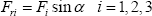
The force balance equation in the X r -direction is:

Where F m and N i are, respectively, the magnetic force of wheel #i and the counterforce of wall against it.
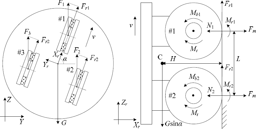
Force and moment analysis during movement (left: bottom view, right: side view along Y r shown on the left)
The torque equilibrium equation around the bottom contact line between the wheel (#2 and #3) and the wall is:

Where N1>0 and which can ensure that the microrobot will not overturn.
The force balance equation in the Z-direction is:

Where F i is the static friction force between the wheel (#i) and the wall and its direction is opposed to that of gravity G.
To prevent the microrobot from sliding along the wall, the sum of the maximum static friction force of the three wheels should be not less than the gravity of the microrobot, i.e.

Where µ1 is the static friction coefficient of the wheel on the wall.
For each wheel (#i), it is driven by the torque M t of the micromotor and it rotates clockwise. Since wheel (#i) has a backward movement trend with respect to the wall, the wall will generate a reaction F ri . The direction of F ri is the same as that of the movement of wheel (#i) and it can be seen as the rolling friction of the wall. Though F ri prevents wheel (#i) from rotating, it is regarded as the traction force in this situation and it is responsible for pushing it so as to move forward. The relationship between F ri and F i can be expressed as:
In addition, since the micromotors of the three wheels are driven synchronously as a whole, the traction force provided by each wheel should be maintained as same so as to avoid slip. Therefore, the maximum static friction force of each wheel must also satisfy the following equation:

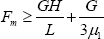
Thus, by equations (2) and (6), the required magnetic force can be derived as:

By the static analysis above, it can be seen that the microrobot can move safely along the wall as long as the required magnetic force is satisfied.
For the wheel (#i), assuming that the rolling resistance moment between it and wall is M ri , the rolling resistance moment generated by the two micro-rolling-bearings in its wheel carrier is M bi . The torque equilibrium equation for the movement of the microrobot can be presented as:

Where M bi = F i ·µ2·r2, with µ2 as the friction coefficient of the micro rolling bearing and r2 as its radius; M ri = N i ·µ3·r, with µ3 as the rolling resistance coefficient between the wheel and the wall.
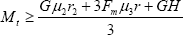
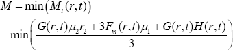
Substituting all of the relative expressions above for the arguments in Eq. (8), the required torque can be derived as:

By equations (7) and (9), it can be seen that the required magnetic force and torque is in direct proportion to the sine value of the direction of the movement (i.e. sinα), and they are up to a maximum when the microrobot moves upwards in a vertical direction on the wall, i.e. α=π/2. Therefore, the following equations should be satisfied:
4. Optimal design of the magnetic wheel
By equation (10), it can be seen that the required torque for the robot is mainly determined by its wheel radius, gravity, height of centre of gravity and the magnetic force. However, the parameters are constrained by each other, and they are all related to the size of the magnetic wheel. A lower torque consumption will lower the supply voltage and current of the robot and, finally, reduce its power consumption. Furthermore, it can improve the load capacity of the robot because the output torque of the micromotor is limited. Therefore, the size of the magnetic wheel is optimized in combination with our own design constraints in the next section, so as to reduce unnecessary torque consumption.
4.1. Constraints
4.1.1. Size of wheel
As shown in Fig. 5, the thickness of the magnetic wheel is t, the radius (also its wheel radius) and the thickness of the round ferromagnetic piece is, respectively, r and t1, while the inner radius, outer radius and thickness of the ring permanent magnet is, respectively, r pi , r po and t2, and the difference between the radius of the ferromagnetic piece and the outer radius of the ring permanent magnet is σ p and the assembly size of the micromotor mounted on the wheel carrier is 7.8mm×6.8mm×4.4mm (l×w×h) in length, width and height.

Structure diagram of the magnetic wheel (left: front view, right: bottom view)
To improve the magnetic force of the wheel, the outer radius of the round ferromagnetic piece should be slightly more than that of the ring permanent magnet so as to allow more magnetic flux to pass through the contact surface. Since both the ring permanent magnet and the micromotor are in axial flux, the inner radius of ring permanent magnet is chosen as equal to half of the width of the micromotor, so as to avoid its interference with the magnetic field of the micromotor and also reduce the volume of the magnetic wheel. For a magnetic wheel with a constant size, it was found that if the ferromagnetic piece is too thin, it will lead to magnetic saturation and thus reduce the magnetic force; if it is too thick, it will offer redundant paths for the magnetic flux of the permanent magnet and increase the volume of the magnetic wheel. Therefore, the design constraint that the volume of a single round ferromagnetic piece be equal to that of the ring permanent magnet is made in order to avoid magnetic saturation as far as possible, to provide enough paths, and also to reduce the number of design variables and thus simplify the optimization design of the magnetic wheel. In addition, the radius of the round ferromagnetic piece should be more than half of the width of the micromotor, otherwise it will not be a useful wheel. Thus, the design constraints of the sizes above of wheel are summarized and expressed as:

4.1.2. Magnetic force of the wheel
By equations (10) and (11), it can be seen that the magnetic force of the wheel should be big enough so that the microrobot can be absorbed on the wall safely, but a greater magnetic force will also increase the required torques. Here, based on equation (10), the design constraint of the magnetic force of the wheel is defined as:
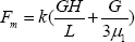
Where k is a safety factor, G = G R + G L , and where G R and G L are, respectively, the gravity of the microrobot body and the maximum designed load carried by it.
4.2. Design variables
By the analysis above, it can be seen that there are mainly four design variables, including t, r, σ p and σ d . To simplify the optimal design of the magnetic wheel, some of the design variables above are determined in advance according to the present level of mechanical machining and assembly techniques, i.e.

Thus, the number of design variables becomes two, namely r and t. By combining their physical meanings and the present level of mechanical machining techniques, their ranges are determined and described as (unit: mm):

4.3. Objective function
The design target is to minimize the required torque consumption of the microrobot by optimizing r and t. Therefore, by equation (11), the objective function is devised as:
4.4. Results
The solution of the permanent-magnetic field is a nonlinear problem. To ensure computational accuracy, ANSOFT Maxwell® 2D was employed. The magnetic force of a single magnetic wheel with a different radius and thickness are computed as shown in Fig 6. Since it is difficult to achieve high machining accuracy (<0.1mm) for a permanent magnet made of fragile NdFeB, the calculation interval (i.e. the optimal resolution) of r is chosen as 0.1mm. Accordingly, the calculation interval of t is chosen as 0.3mm. Since the mechanical structure of the microrobot is not regular, its CAD model (including the maximum designed load of 3g mounted on its chassis - i.e. G L =29.4mN - which we assume to be the microsensor carried by it) for a different radius and thickness are developed using Pro/Engineer simulation, so as to calculate their gravity and the height of their centre of gravity accurately, as shown in Fig 7. With the following parameters initialized: µ1=0.3, µ2=0.001, µ3=0.5, r2=1.5mm, k1=1.5, the eligible design variables can be found, firstly, by equation (13), followed by the computation of the required torque by equation (16), and finally the determination of the minimum.

Results of ANSOFT simulation
The results for the eligible design variables are listed in Table 1, including gravity, the magnetic force of wheel, height of the centre of gravity, and the required torque. From Table 1, it can easily be seen that the required torque is minimized when the radius and thickness of magnetic wheel are, respectively, 4.9mm and 2.1mm. The optimal results are labelled in bold font in Table 1. By analysing the results in Table 1, the following conclusion can be obtained: with the design constraints detailed above, neither the smaller nor the larger wheel radius will minimize the required torque. The reason is: the bigger wheel radius will increase the height of the centre of gravity of the microrobot, thus increasing the required torque; although a smaller wheel radius is helpful for reducing the height of the centre of gravity, the thickness of the magnetic wheel will have to be increased so as to satisfy the required magnetic force. Besides, this will also increase the gravity of the microrobot, thus increasing the required torque on the whole. Therefore, it can be seen that the torque loss of the microrobot can be minimized by the above optimal design.
Relative results of the design variables satisfying the required magnetic force


Results of Pro/Engineer simulation

Photograph of the microrobot next to a 16mm coin
5. Experiment
A prototype of the proposed microrobot was fabricated according to the optimal results presented above. The size of the microrobot body is 26mm in diameter and 16.4mm in height, and its mass is 7.2g, as shown in Fig. 9. The magnetic force of the microrobot was tested by using a spring dynamometer with a resolution of 1mN. The total value of its three magnetic wheels is 943mN, which is about ten times the gravity of the microrobot.
The control system of the microrobot is based on a host computer and a slave control unit using serial port communication. The slave control unit mainly consists of a microcontroller (LPC2104) base on a 16/32-bit ARM7TDMI-S CPU, and a driver (ATA6836) including six independent half-bridges. The driver is connected with the microcontroller by a serial peripheral interface bus, and both the high-side and low-side drivers of each half-bridge can be controlled separately. The micromotors of the three magnetic wheels are connected in parallel and are driven by three half-bridges. Thus, they can be controlled as a whole by inputting the same signal for the translational movement of the microrobot. The other three half-bridges are used to drive the steering micromotor of it. A visual control panel was developed in the host computer using Visual C++ 6.0 and the user can transmit related commands (such as translation, steering, stop, velocity set, etc.) to the slave controller by it, thus controlling the movement of the microrobot.
An experiment whereby the microrobot avoids obstacles and moves along a broken line on an erect ferromagnetic plate was firstly done to demonstrate its wall-climbing ability and flexible mobility, as shown in Fig. 10. In the experiment, the microrobot starts from point S, avoids and goes through the raised grids on the ferromagnetic plate, and finally arrives at the destination point D. The basic control process is that the microrobot should move linearly to a corner first, and then immediately stop so as to quickly adjust the direction of its wheels in situ due to its zero turning radius, and then continue to move towards the next corner. Thus, the microrobot can quickly arrive at its destination via several broken-line movements. During steering, the micromotors for translational movement need to be electrified continuously so as to prevent the magnetic wheels from rolling down. In addition, and in order to reduce the power consumption of the microrobot, its wheel direction should be adjusted to 0° (i.e. α=0, the power consumption is equal to 0 by equation (9) at the time) after it arrives at the destination point D and remains stationary. With an external supply voltage of 6V, the microrobot can move at a speed of 2.5cm/s and its load capacity can be up to 3g.
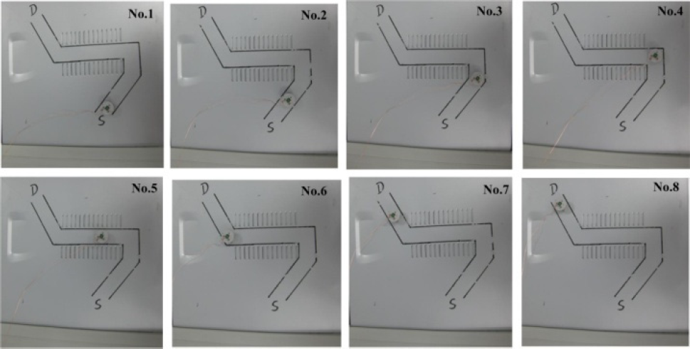
The microrobot goes through and avoids an obstacle zone
In addition, to explore the application of the microrobot further, a microcamera module was developed. The microcamera (size: 20mm×20mm×5mm, mass: 2.9g) is a low voltage 1/6 inch CMOS image sensor (OV7670) with 300K pixels (image size: 640×480). To improve the image acquisition rate, a camera control processor (MV3018) with 1Mbit of embedded memory and hardware-based real-time JPEG compression and decompression was chosen to wholly control it. Thus, the slave control of the microrobot can directly gain the compressed images through the data bus interface of MV3018. A related experimental scene where the microrobot carries the microcamera and performs visual crack detection in a ferromagnetic pipe is shown in Fig. 11.

The microrobot performs visual crack detection in a ferromagnetic pipe
6. Conclusion
This paper presented the design and optimization of a compact omni-directional magnetic wheeled wall-climbing microrobot actuated by MEMS-based electromagnetic micromotors. The integral design with an actuator and adhesive not only reduces the volume of the magnetic wheel but also improves its driving efficiency. Under the condition of a tiny size limit, the microrobot developed has the advantages of a simple mechanical structure, high reliability, low power consumption, high driving efficiency, flexible mobility and good load capacity. Future work will mainly focus on developing an autonomous control system for the microrobot with a lower mass, volume and power consumption by adopting advanced SOC technology, and so that it can carry out some non-destructive inspection tasks autonomously in a real ferromagnetic environment.
Footnotes
7. Acknowledgments
This work was supported by the National Natural Science Foundation of PRC (No.61175100) and the Research Fund of Medicine and Engineering of Shanghai Jiao Tong University (No. YG2011ZD01).