
Abstract
The public healthcare system in South Africa is in need of urgent attention in no small part because there has been an escalation in the number of stroke victims which could be due to the increase in hypertension in this urbanizing society. There is a growing need for physiotherapists and occupational therapists in the country, which is further hindered by the division between urban and rural areas. A possible solution is a portable passive physiotherapeutic exoskeleton device. The exoskeleton device has been formulated to encapsulate methodologies that enable the anthropomorphic integration between a biological and mechatronic limb.
A physiotherapeutic mechanism was designed to be portable and adjustable, without limiting the spherical motion and workspace of the human arm. The exoskeleton was designed to be portable in the sense that it could be transported geographically. It is a complete device allowing for motion in the shoulder, elbow, wrist and hand joints. The inverse kinematics was solved iteratively via the Damped Least Squares (DLS) method. The electronic and computer system allowed for professional personnel to either change an individual joint or a combination of joints angles via the kinematic models. A ramp PI controller was established to provide a smooth response to simulate the passive therapy motion.
1. Introduction
There are 50 million people living in South Africa and 52% of the population are resident in rural areas [20]. It was therefore essential to design a portable system that allows a physiotherapist to easily transport the mechanism between urban and rural areas. This will provide individuals with physiotherapy which is not well established in rural areas.
An exoskeleton arm is an anthropomorphic external mechanical structure that allows for the transfer of mechanical power from the exoskeleton structure to the human arm [1]. A device such as this allows for physiotherapy rehabilitation and an exoskeleton arm is intended to provide passive therapy to stroke victims in order to prevent spasticity in the joints. Clinical trials have proven that passive robotic therapy results in improved rehabilitation in the shoulder and elbow motion of spastic hemiparesis patients as compared to traditional physiotherapy [3]. Passive therapy is the movement of a limb segment created completely by an external force; it is a non-restrictive motion and therefore only requires positional motion of the mechanism.
An exoskeleton arm is a bio-mechatronic system, which is the integration of mechanical, electronic, software engineering and biology (the human arm). This integration is illustrated in Fig 1.

The integration of various disciplines which result in a bio-mechatronic system.
Traditional rehabilitative exoskeleton arms implement three mutually orthogonal serial joints which imitate the spherical motion that is achieved by the glenohumeral joint (GH joint). It is essential to attain such a motion in order to replicate the Activities of Daily Living (ADL) which will achieve the large workspace required for physiotherapy.
However, it is difficult to replicate the spherical motion produced by the GH joint in a portable supported exoskeleton. The reason for this is that the exoskeleton has to be anthropomorphic and three orthogonal joints will cause interference with the human arm or produce a bulky structure, which is undesirable for obvious reasons. It is important to consider arm lengths and since each individual has different arm sizes, adjustability has to be taken into consideration. This adjustability means that the kinematic model has to be updated for different adjustments. Inverse kinematics is implemented, numerically, into the system to allow a physiotherapist to place the hand (end-effector) at a position that will provide efficient movement in a combination of joints. The DLS method is implemented, which overcomes the complexity of the system.
The exoskeleton arm will respond to instructions determined by a physiotherapist. These instructions could be task space in terms of position and will be relative to the base point, which is the GH joint and is represented by X0 and Z0 in this paper. The instructions could also be in terms of joint space which will be the change in angle of a specific joint, or a combination of joints. These positional changes will assist the mechanism in placing the upper-limb at various workspace positions in order to create the passive therapeutic motion.
The paper covers the concept of the biomechanics for the human arm and a literature survey of previous designs. The mechanical design is presented which illustrates the different mechanisms used and the adjustability of the system. The kinematics section explains the inverse kinematics and joint limits of the exoskeleton arm. An explanation of the implemented control system is also presented. Finally, the results and a discussion conclude the paper.
1.1 Bio-mechanics of the human arm
The human arm consists of various Degrees Of Freedom (DOF) which must be taken into consideration in order to design a successful exoskeleton structure. The shoulder, elbow, wrist and hand (excluding fingers) joints yield 7 DOF. These include extension/flexion (ext/flx), adduction/abduction (add/abd) and lateral/medial (lat/med) rotation which are produced by the shoulder joint; the elbow joint produces supination/pronation (sup/pron) and flexion of the forearm, and the wrist joint creates ext/flx and add/abd of the hand. Fig 2 [5] illustrates the above explained DOF in the human arm. Sup/pron movements are propagated by the ulna and radii bones which are connected to the elbow and wrist joints.

DOF in the human arm.
However, this motion affects the lower part of the forearm, thus affecting the orientation of the end-effector. This has to be taken into design consideration. As previously explained, the spherical motion is created by the shoulder joint and is the fundamental motion required to produce a workspace according to the ADL. Mechanically this is usually achieved by three serial orthogonal joints; which is in this case not feasible as previously described. The mechanical design is further complicated with the presence of singularities. A singularity is created when two joint axes become co-linear; any further rotation regarding the joints will yield the same result. This results in a loss of a degree of freedom [6]. As a result, the Jacobian reduces in rank and the matrix will command an infinite speed in the relative joint axes, which is undesirable for obvious reasons [7]. A singularity cannot be removed from the mechanical design, however, it can be moved to a position which will not hinder the ADL. This placement will be explained further in this paper.
1.2 Previous designs
Traditional rehabilitative exoskeleton arms are bulky and their mechanical manipulators are not designed to be portable. However, their designs can be extremely useful with regard to certain criteria, such as joint analysis and achievable workspace. Four exoskeletons (CADEN-7, MAHI, MGA and ARMin II) were analysed in terms of their joint angle ranges and this is compared to the ADL. This comparison is tabulated and can be seen in Table 1 [adapted from [8]].
Range of joint angle motion which corresponds to the various DOF.

The tabulated values printed in red are joints that are capable of rotating more than the human joint can handle. This can cause severe damage resulting in hyper extension or flexion of the human joints, therefore, safety is an essential factor in this design and the proper implementation will be discussed further in this paper.
1. The CADEN-7 uniquely implements several control algorithms one of which is for the purpose of rehabilitation.
It also successfully imitates the three DOF in the shoulder joint and the sup/pron rotation, as tabulated in Table 1. However, it is actuated via a pulley system which remotely adds extra weight and therefore requires a fixed external support structure.
Thus, portability is not achievable. It is also limited in terms of adjustability due to the additional cables in the pulley system – see Figure 3 [10] which is a computer aided drawing (CAD) of the CADEN-7.

The CADEN-7.
As can be seen from Figure 3, the pulley actuation adds extra bulk to the system and therefore results in non-portable system [10].
2. The L-EXOS is similar to the CADEN-7 in terms of the pulley actuation and structural design. It consists of three mutually intersecting orthogonal joints which emulate the spherical motion of the GH joint. This motion is desirable, however, the orthogonal layout is undesirable as previously explained. The L-EXOS can be configured to allow for the hand to be implemented into the end-effector, which is required for this research. However, this is purely for a virtual environment and only makes use of the thumb and index finger [9]. The L-EXOS can be seen in Figure 4.

The L-EXOS exoskeleton.
3. The MAHI is a haptic exoskeleton designed for training and rehabilitation. It implements an actuation layout that consists of a revolute prismatic spherical (RPS) parallel mechanism.
This mechanic layout creates the required pron/sup rotation, but it does not allow for any shoulder motions [13]. Its elbow design can be implemented into this research and although the 3 RPS layout maybe effective for the MAHI the extra actuators combined with a shoulder mechanism will add extra weight. Figure 5 [13] is a picture of the MAHI exoskeleton.

The MAHI exoskeleton.
4. The MGA exoskeleton, Figure 6 [5], allows for scapula rehabilitation which adds a DOF to the design. However, its structure compensates for the spherical workspace by allowing for a joint layout that is not mutually orthogonal. The MGA makes use of DC motors for the individual joints, therefore, not requiring an external support for actuation. The structure has a hand support and not an exoskeleton hand, thus not accommodating the full upper-limb, but its joint layout and actuation setup will be implemented in this design.
The MGA exoskeleton design.
The above described designs consist of motion in certain segments of the upper arm; none of which can rehabilitate a combination of the shoulder, elbow, wrist and hand (gripping) joints. It was therefore decided to implement such a combination as a contribution to this area of research, together with the concept of portability, spherical workspace, adjustability and inverse kinematics with the DLS method.
2. Mechanical design
It is difficult to implement hydraulic or pneumatic actuators in a portable exoskeleton system because these actuators require reservoirs for either the oil or compressed air [7]. This results in an impractical and bulky solution. The MGA exoskeleton used electric motors for each joint thereby reducing the need for a bulky pulley system. It was therefore decided to use geared electric motors following the success of the MGA [7].
Wrist ext/flex and add/abd was excluded from this design in order to create a simpler and lighter structure. This omission limits the orientation of the wrist which will not be necessary for rehabilitation purposes because sup/pron movements will provide wrist rehabilitation around the carpus region [14] and this motion will reduce stiffness of the joint. The exclusion of the wrist DOF results in a 5 DOF manipulator which includes abd/add, flx/ext and med/lat rotation of the GH joint, and flx/ext of the elbow and sup/pron of the wrist. The exoskeleton hand will be in an intrinsic position allowing for the movement of both sides of the carpus bones [14]. This will allow for the four fingers to meet with the thumb at a symmetric point. The hand mechanism will therefore require an additional 2 DOF, hence resulting in a 7 DOF system and a 4 DOF manipulator.
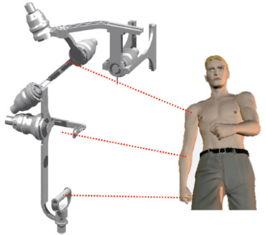
Figure 7 illustrates the shoulder, elbow, wrist and gripping (carpus) joints by circles 1–4 respectively, the connection between these joints are represented by I, II and III respectively. Each arrow represents the respective DOF as previously explained. The design of the hand and the wrist will be discussed further in this section.
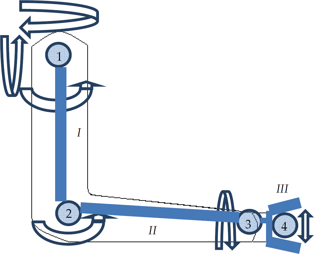
A systematic integration of the 7 DOF in this design.
The shoulder joint is complex and results in the desired spherical motion; achieving this motion via three intersecting orthogonal joint is undesired. It has been proposed that three serial mutually intersecting joints at the shoulder, which obey inequalities (1) and (2), will produce the required spherical motion for the required workspace, as discussed in this paper [7].


Where θ1, θ2 and θ3 ranges from 0 to π and are the angles between joint 1 and joint 2, joint 2 and joint 3 and joint 3 and the end-effector (tool tip) respectively. The three joints represent the GH joint at a mutual intersection and these joints will be illustrated in the conceptual designs further in this section. Figure 8 [5] illustrates the relationship of the above described angles and the tooltip.
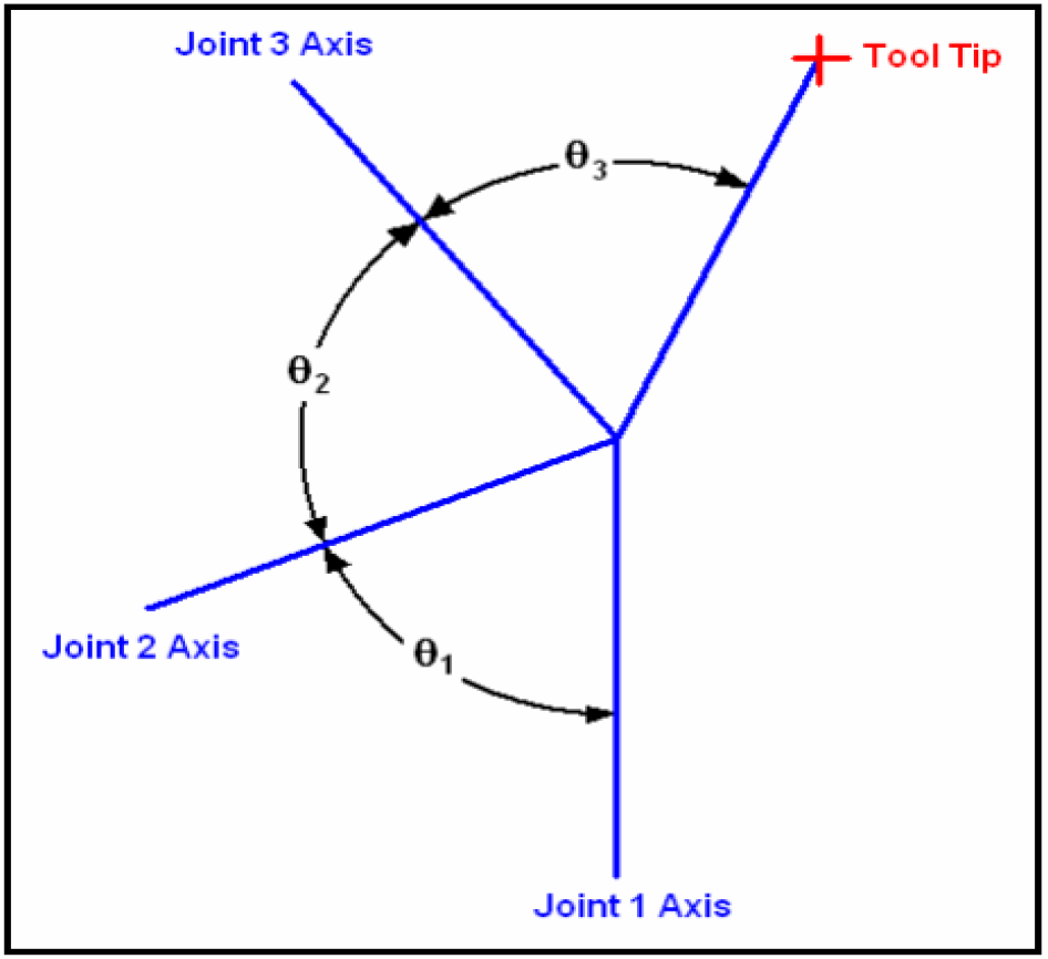
The three joint axes' angles and the tool tip direction.
By rotating the tool tip around joint axis 3, a circular path will be outlined, this is represented by the green circle in Figure 9 (b) [5]. A further rotation of this circle around joint axis 2 results in a spherical surface bounded by joint axes 2 and 3. The orange sphere in Figure 9 (c) [7] represents this surface. By further rotating the orange structure around joint axis 1, a complete sphere is obtained. Inequalities 1 and 2 therefore need to be satisfied in order to achieve the required spherical workspace [5].

The spherical motion.
The relationship between the shoulder joint axes forms the fundamental foundation of this research, therefore, inequalities 1 and 2 must be satisfied in order to provide the spherical workspace. Once a suitable relationship is obtained for the three intersecting joints, a serial joint can be easily linked to the shoulder mechanism – this will represent the elbow joint.
The final design in Figure 10 was designed around inequalities 1 and 2; this resulted in θ1, θ2 and θ3 equating to 900, 750 and 450 respectively; with the direction of the tool tip taken along the upper arm.
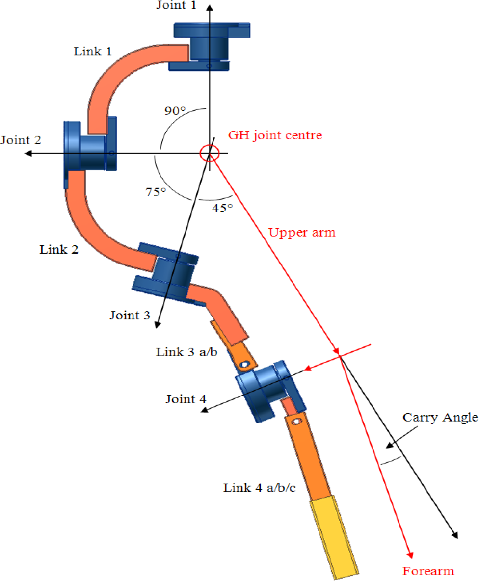
The relative links and joints.
2.1 Wrist mechanism and hand exoskeleton
The wrist mechanism provides motion in the hand, wrist and the forearm. This will produce the relevant supination and pronation movements. The mechanism was easily achieved by using a pinion and a semi-circular gear which was inspired by the ARMin II [15] exoskeleton. The pinion and semi-circular gears are encased in a gear cover. The ARMin II makes use of a steel cable which rotates in a semi-circular cuff.
A gear system was implemented for safety reasons and to eliminate the possibility of cable failure. The semi-circular gear turns in a slot with power supplied via the pinion gear which is actuated by a dc motor. The lower forearm of the individual is strapped to this gear and the supination/pronation movements are created as a result of the rotation of the semi-circular gear. This system is connected to link 4 and therefore can be adjusted via the forearm. The wrist mechanism can be seen in Figure 11 [8].
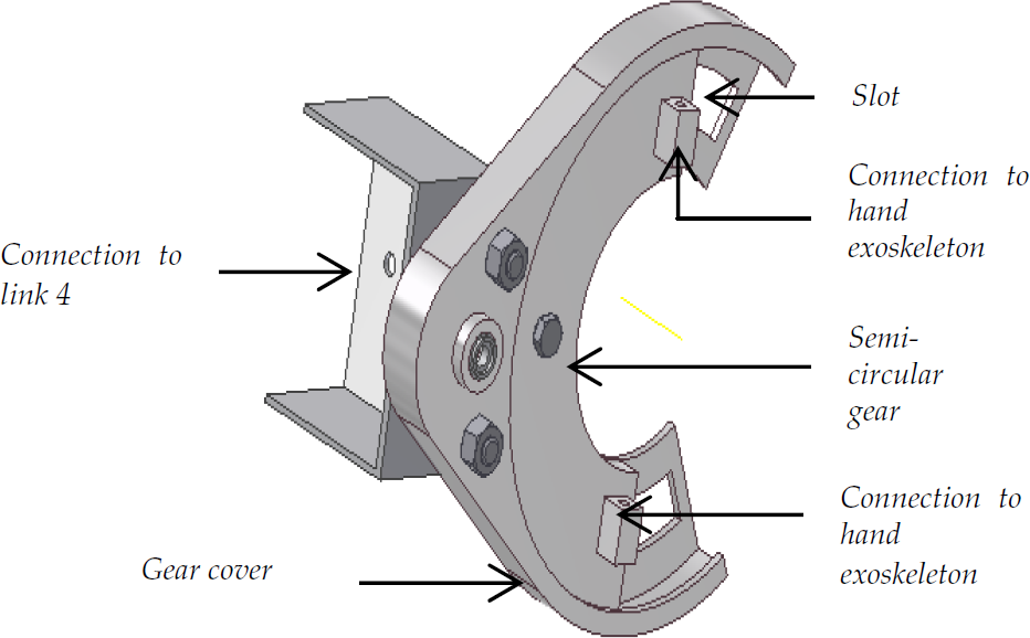
The wrist mechanism
The exoskeleton hand allows for the human hand to be placed in an intrinsic position. This provides the gripping motion which consists of the movement of the four fingers (combined motion) and the thumb at the carpus bone, therefore, the thumb and the four fingers can approach each other. This mechanism, Figure 12, is connected to the wrist mechanism.

The exoskeleton hand.
2.2 Adjustability
The shoulder joint is not mechanically adjustable, however, the links are designed for the 95th percentile human arm. The 95th percentile arm is statistical information on individuals that have larger arm dimensions than the average human being.
The mutual intersection is designed such that the three serial joints will represent the GH joint of an individual that has dimensions greater than the average human or individuals that are smaller than the 95th percentile. Therefore, the shoulder mechanism will be adjustable in the sense that it will represent both the average and above average individual's GH joint. The elbow joint is mechanically adjustable as it allows for the forearm length to be adjusted via square tubing. The above adjustments were implemented into the chosen conceptual design and this resulted in the final design which can be seen in Figure 13 [8]. Links 3 and 4 consist of rectangular tubing with slots on the inner layer and holes in the upper layer. This allows for the tubing to be adjusted and then bolted at a desired position via the upper layer holes and the inner layer slots.

The final exoskeleton mechanism.
Figure 14 illustrates the implementation of portability; the base support is large enough to support the centre of mass of the exoskeleton when connected to the user. It is portable and is geographically transportable.
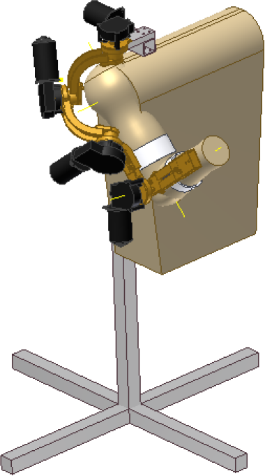
The final shoulder and elbow mechanism connected to the portable stand.
3. Kinematics
The kinematic models allows for a simulation of the workspace and for positional control during physiotherapy. The joint frames and transformation matrices are derived using the Denavit-Hartenberg (DH) notation – this is the most common method used for manipulator kinematics [16]. It involves the derivation of DH parameters which are used to solve the transformation matrices. The joint schematic of the positive X and Z axes of the final design is illustrated in Figure 15 [8]. X0 and Z0 represent the base frame's X and Z axes respectively.

Joint schematic of the final design; X0 and Z0 represent the base axes.
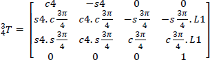
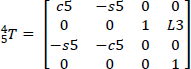
Where αi, ai, di and ϑ i are the four DH parameters and represent the twist angle, link length, link offset and joint angles of joint i respectively. These parameters are tabulated in Table 2 and are according to the DH notation; further methodological information can be found in [16]. The variable ϑ in the kinematic model is different to that previously specified. ϑ i represents the angle from Xi–1 to Xi about Zi [16]. Equation 3 [16] is the transformation matrix of joint i relative to the previous joint. The first three rows of column four, in Equation 3, represented in red are the X,Y and Z co-ordinates of joint i relative to joint i-1 [16]. This will be used to solve the inverse kinematics. The individual joint transformations are obtained by substituting the tabulated parameters into Equation 3.
DH parameters of the final design.

These are represented by matrices 4, 5, 6, 7 and 8 [8]. Where s1 and c1 represent sine(ϑ1) and cosine(ϑ1) respectively. L1 and L3 are length parameters and represent the distances from the GH joint to the elbow joint and the length from the elbow joint to the centre of the end-effector respectively, and vary with changes in adjustability.


The forward kinematics can be obtained by a matrix multiplication of matrices 4–8 and is represented by Equation 9 [8]. This represents the transformation matrix of the end-effector with respect to the base frame.

The forward kinematics will determine the change in X, Y and Z for a combination of joint angle changes. A simulation of the workspace of the device can be achieved with the forward kinematics of the exoskeleton. This will determine if the shoulder mechanism produces the desired spherical motion. The workspace of the device is created by taking joint constraints into consideration. ϑ1, ϑ2, ϑ3, ϑ4 and ϑ5 are constrained to −300 to 1500, −1500 to −300, 00 to 1370, 00 to 1200 and 00 to 1750, respectively, according to the kinematic models.
These joint constraints are implemented for safety reasons, therefore preventing link collision, collision of the mechanism with the user and hyper extension or flexion of the human joints. The values for L1 and L3 were taken to be 250 and 350mm respectively. This resulted in the simulation illustrated in Figure 16. The X and Z axes (Figure 16) are according to Figure 15 and respectively represent the X0 and Z0 axes.
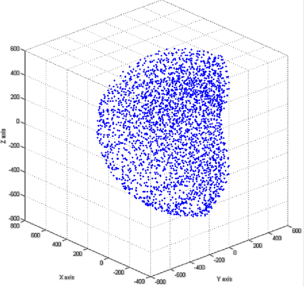
Workspace of the exoskeleton mechanism which results in a spherical motion.
The workspace of the exoskeleton possesses a spherical nature and therefore results in a successful spherical motion which is inherent in the shoulder mechanism. The forward kinematics is essential as it allows for a visible workspace and forms a foundation for the inverse kinematics which will be explained in the following section. The simulation of this workspace was created using a nested ‘for loop’ and an array layout. The ‘for loop’ ranges from the minimum to the maximum joint limits of joints 1–4 by which the condition incremented by 20 degrees for joints 1, 2 and 3. Joint 4 was incremented by 10 degrees to achieve a better resolution. The forward kinematics position of each simulated point was then plotted as illustrated in Figure 16.
3.1 Inverse kinematics
The distance between joints 2 and 3 and joints 3 and 4 are 750 and 1350, respectively. This means that the transformation matrices consist of more non-zero terms, which results in a complex algebraic inverse solution. The non- orthogonal layout produces a difficult geometric solution which is further coupled by a 3- dimensional problem. This is evident from the methods illustrated in [16]. Buss [17] proposes several inverse kinematics iterative methods of which the DLS method is superior around singularities and complex designs. The DLS method implements the Jacobian of the positional vector of the mechanism and is required to solve the change in ϑ i [17].
Matrix

The iteration of small angle changes is a function of the Jacobian and results in a linear derivation of the inverse kinematics.
The Jacobian is represented by Equation 11 [17]. This will result in an m x n matrix; in this model m=3 and n=4.

The change in ϑ i can be determined by Equation 12 [17].

J', λ and I respectively represent the Jacobian transpose, damping factor and identity matrix. The damping factor compensates the computational problems as a result of singularities [18]. The multiplication of the Jacobian with its transpose produces a square matrix which allows for the computation of the inverse of this multiplication. The error value is the difference between the initial position and the target position. This is updated in the iteration. The algorithm of the DLS method is illustrated in Figure 17. The iteration process is dependent on the error value which is initially calculated. The angle change is then iteratively solved and the error value and joint angles are updated. This process is repeated until the error value is reduced to a desired tolerance.

The iteration process of the DLS method.
3.1.1 Joint limits
Na et al. [18] proposed a method to limit the joints according to the desired constraints with a weighting which relates to the joint flexibility. This is implemented by modifying the damping factor by inserting an n x n diagonal matrix which is illustrated by Equation 13 [18].

The individual damping factors are represented by Equation 14 [18]].

Where c and p are user defined functions with p as an even number. ϑ i is the angle of joint i during the iteration process and is updated as the error decreases, according to Figure 18. ϑ max and ϑ min are the maximum and minimum limits of the respective joints. wi is the user defined weighting according to the flexibility of each joint. The original DLS method implements a constant damping factor. However, Equation 14 produces a small damping factor when within joint constraints and a large damping factor when near joint limits which result in a feasible solution [18]. This can be seen in Figure 18 [18].
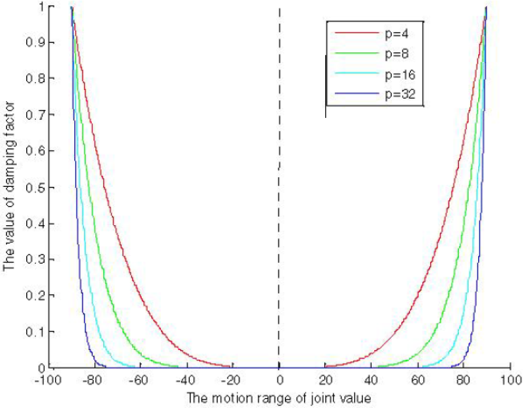
Damping factor curve for motion range of a joint with c =1, ϑ max = 900 and ϑ min = −900.
It is visible from Figure 18 that a lower p value allows for a wider range of motion, therefore, a value of 4 was chosen in this research. This value will enable a larger motion range with regard to the joint angles.
Implementation of the diagonal matrix into the DLS methods results in Equation 15.

The diagonal matrix, Equation 13, is an n x n matrix and, therefore, the addition in Equation 15 requires the J'J matrix multiplication. This allows for a conversion of the m x n Jabcobian matrix into an n x n square matrix that can be inverted successfully. This is multiplied by the error value as illustrated in Equation 15.
4. Control implementation
Based on the kinematical model presented in this paper, control architecture was developed and implemented according to the algorithm illustrated in Figure 20. The physiotherapist will enter the X, Y and Z positions of the end-effecter. These values are processed by the kinematic model illustrated in Figure 17 and sent to the microcontroller which performs the necessary motor control. The desired joint angles may also be entered; in this case the kinematic model will be bypassed. A PI ramp controller is implemented in this system in order to minimize overshoot in joint angles. Initially a PID step controller was implemented, however, this produced an initial jerky motion which was not desired. The comparison between the two controllers is illustrated in Figure 19, it is visible that the initial gradient of the ramp response is lower than that of the step response. The resolution of the encoders was only accurate to a degree and therefore the lines in Figure 19 appear to be coarse.

Comparison between the PID step response and PI ramp response.

Control strategy for future control algorithms.
5. Safety
Safety is essential in an exoskeleton arm in order to prevent hyper extension or flexion of the joints and is implemented by mechanical stops, electronic sensors (limit switches) and software control. The combination of the three implementations results in a safe bio-mechatronic system.
6. JLDLS results
The implementation of the joint limits was tested and tabulated in Table 3. Table 3 illustrates the comparison between the Joint Limited Damped Least Squares (JLDLS) and the original DLS. The values highlighted in red in Table 3 are the values that do not obey the joint constraints which were previously stipulated. The bold values (Table 3) are obtained using Equation 15 and overcame the problem highlighted in red. These values were obtained from an initial position of 00, −450, 750 and 00 for ϑ1, ϑ2, ϑ3 and ϑ4, respectively.
A comparison of the JLDLS and DLS methods for different end-effecter positions.
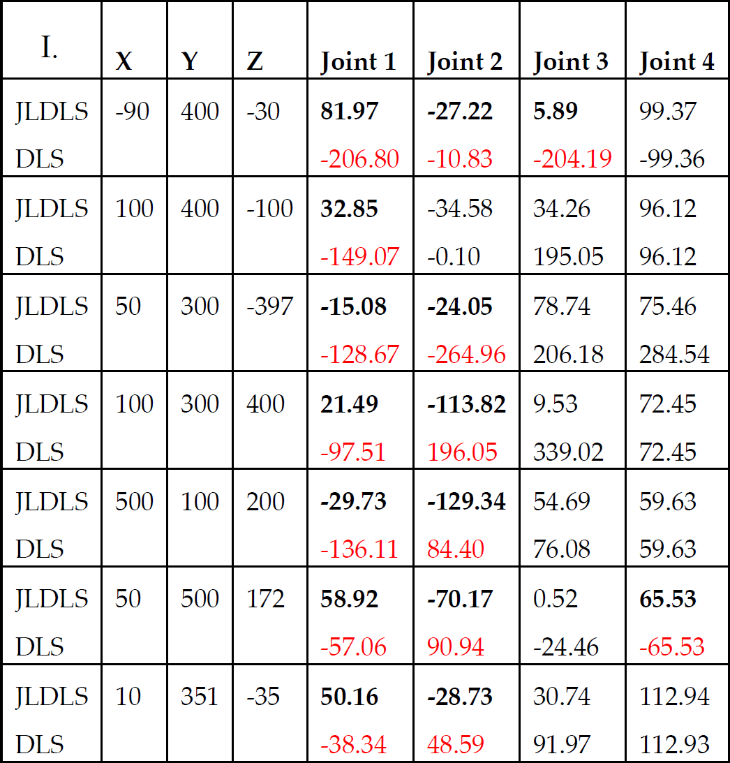
Figure 21 and 22 represents the minimization of the error value for each axes and the change in joint angles respectively. The error value is reduced to 0 at approximately 160 iterations of the algorithm depicted in Figure 17.

The minimization of the X, Y and Z error values, against the number of iterations.
This convergence to zero is illustrated by Figure 21 and the joint angles become stable at their respective values as the error values approach zero. The stabilization of the joint values and the minimization of the error are dependent on the iteration count. The iteration count can be further increased by minimizing the tolerance of the error value and this will result in a more accurate solution. The stabilization of the joint values, Figure 22, as the error values minimizes illustrates that a successful JLDLS was implemented on a redundant manipulator.

The stabilization of the joint angle values.
7. Manipulator's range of motion
The different range of joint motions were tested. The exoskeleton manipulator was driven to its joint limits in order to determine its workspace angles. The following joint motions were analysed:
Shoulder abduction
Shoulder flexion/extension
Shoulder medial/lateral rotation
Elbow flexion/extension
Wrist pronation/supination
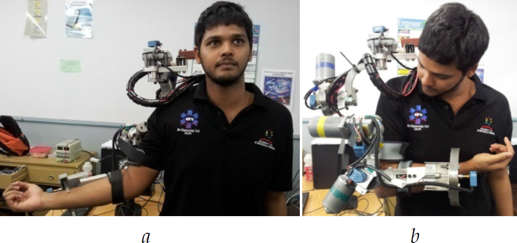
The DOF as described above were tested and photographed. Shoulder abduction and flexion/extension are illustrated in Figure 23 (a) and Figure 23 (b), respectively.

(a) Shoulder abduction. (b) Shoulder flexion.
Figure 24 (a) and Figure 24 (b) illustrate the maximum shoulder extension and elbow flexion, respectively.
(a) Shoulder extension. (b) Elbow flexion.
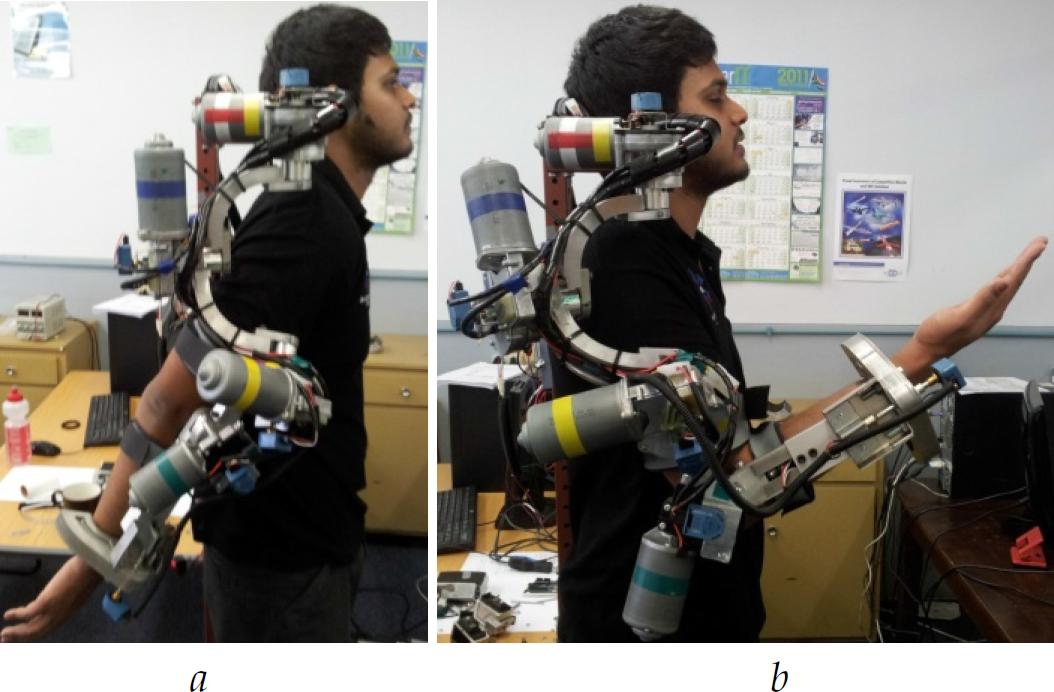
Shoulder lateral and medial rotation is illustrated in Figure 25 (a) and Figure 25 (b), respectively.
(a) Shoulder lateral rotation. (b) Medial rotation.
Figure 26 (a) and Figure 26 (b) illustrate the supination and pronation movements, respectively.

(a) Wrist supination. (b) Pronation.
The workspace tests were concluded as follows in degrees.
Shoulder abduction/adduction – 1100/450
Shoulder extension/flexion – 300/1350
Shoulder lateral/medial rotation- 400/900
Elbow flexion – 1200
Wrist pronation/supination – 850/850
These values are impressive considering that the exoskeleton is portable and adjustable. The range of motion can be further compared to the motion of the previous exoskeletons and the ADL which is tabulated in Table 1.
8. Conclusion
This paper illustrates the development of an upper-limb passive therapeutic exoskeleton that can be used for physiotherapeutic purposes. The exoskeleton is portable in the sense that is can be moved from one geographical location to another. The mechanical attributes result in complicated kinematics which requires the solution of inverse kinematics via iterative methods. The joint limits were constrained by taking redundancy into consideration and manipulating the damping factor which resulted in an inverse kinematics model that obeyed a combination of joint constraints. The desired spherical motion which is essential for a large workspace was achieved and this overcame the need of mutually orthogonal joints. This workspace was created without the hindrance of singularities. The results of the joint limited method proved successful as compared to values from the original DLS. The stabilization of joint angles as the error values approach zero results in a successful implementation of the DLS method. The range of motion of the exoskeleton was established and was greater than that of the ADL which is impressive considering that the exoskeleton is adjustable and portable. Therefore, a portable, non-singular and adjustable exoskeleton which is inherent of a large workspace with implemented DLS was designed.