
Abstract
The present work, which describes the mechatronic design and development of a novel rehabilitation robotic exoskeleton hand, aims to present a solution for neuromusculoskeletal rehabilitation. It presents a full range of motion for all hand phalanges and was specifically designed to carry out position and force-position control for passive and active rehabilitation routines. System integration and preliminary clinical tests are also presented.
1. Introduction
More than 200 million people worldwide live with some type of disability [1]. Among them are a large number of people with motor disabilities. This renders rehabilitation a primary challenge with the goal of helping and improving the quality of life for patients through either traditionally-assisted physiotherapy or by using new technologies in rehabilitation centres.
Robotics has led to the significant innovation of traditional rehabilitation methods. The use of robotic systems has greatly evolved and improved human quality of life; the repeatability, precision, control and accuracy in the movements of a robot can offer patients extremely thorough rehabilitation routines.
During the past few decades, research in the field of rehabilitation robotics has focused on developing upper extremities robots [2, 3]. On the other hand, some of the disadvantages of these technologies include high cost, making them accessible to everyone, as well as the fact that many of these systems, developed by laboratories, are not commercially available.
In general, these rehabilitation machines are robotic exoskeleton systems worn on the patient's joints, helping them perform physiotherapy training and supervising the established routines needed to accomplish their rehabilitation. The primary causes of hand disabilities are neuromusculoskeletal diseases such as the tetraplegia, hemiplegia, tendonitis, broken bones and degenerative illnesses like arthritis, which affects the motion of fingers in the hand. In order to be treated, these illnesses require opportune active and passive physiotherapy treatments to avoid permanent damage to the joints. Passive assisted rehabilitation requires the physiotherapist to apply many flexion-extension movement repetitions to the fingers of patients, whereas active rehabilitation focuses in flexibility training and specific stretching exercises for each injury. When a normal range of motion has been established and can be maintained, force training is introduced to restore strength [4].
One of the biggest limitations when designing hand exoskeletons is its complex morphology; this is due to the need to adapt it to different human hand sizes. At present, exoskeleton robots such as the HX [5] offers adaptability to the anthropometric variability and different mechanisms of the hand, as well as self-alignment mechanisms to absorb human/robot joint axes misplacement. It also presents an advanced mechanical design for achieving this adaptability and mobility. Another robot that aims to focus on adapting to the varied size of human fingers is the exoskeleton developed by the Harbin Institute of Technology [6], where the transmission system is performed by a cable, with actuators mounted on the forearm of the user. The Handexos [7] and the Sabanci University hand robots [8] solve the issue of adapting to different finger sizes.
Assuring independent movement for each of the joints in the fingers is one of the most complex aspects of the mechanical design of hand exoskeletons. Robots such as the Hand I [9] and the CAFE (cable actuated finger exoskeleton) [10] focus on addressing this problem and perform the independent control of movement, speed and torque for each of the finger phalanges. The Festo Company developed the ExoHand [11], a hand exoskeleton whose main characteristic is the individual finger motion applied principally to increase user strength, transferring skills from human to robot and BCI. Though this robot can be used by different hand sizes, it does not present perfect fitting in terms of the phalanges because it has been mechanically designed for one hand size. It is a pneumatically actuated robot and as such, it is robust and not especially portable. Carnegie Mellon University [12] presents an orthotic exoskeleton system that was mechanically designed to assure independent movements for each phalange and to be adapted for different human hand sizes. However, this solution was exclusively designed to be a human index finger orthotic robot, it also presents pneumatic actuators that increases its weight and renders it a non-portable device.
Control is a major aspect that enables hand exoskeletons to provide repetitive and accurate movements. Therefore, on the issue of strength and position control, much research has addressed the use of specialized sensors for obtaining strength and position [13, 14, 15, 16, 17, 18]. Furthermore, bio-signals such as the EMG have also been tested in this field. The most relevant work completed in this field includes the index finger of the Pittsburgh University hand [12], which totally controls the movement of the finger with EMG signals located in the biceps of the user. The Milan University hand [19] was designed with the objective of helping people who have partially lost the ability to correctly control the hand musculature. Another important rehabilitation exoskeleton is the EMG-controlled robotic hand exoskeleton for bilateral rehabilitation [20], which can be adapted for a varied range of finger sizes; however, as its objectives are aimed carrying out bimanual training for hand grasping, there is no independent movement for each phalange in this exoskeleton. The five-fingered PAM hand exoskeleton, driven by pneumatic artificial muscles with polypyrrole sensors [21] is an exoskeleton with 19 DOF that assures independent movement of each phalange of the robot. Additionally, PAM offers similar characteristics to biological muscles; however, its adaptation to different finger sizes has not been fully solved.
The ExoK'ab robot (K'ab being a Mayan word meaning “hand”) presented in this study aims to design and develop a compact, light-weight solution, with independent motion on each phalange, complete position sensorization and the capability to exert forces that fulfil the specifications obtained in a preliminary ergonomic study on patients for particular rehabilitation protocols that demand position and force control.
The present robot is an original hand exoskeleton focused on hand-motor-rehabilitation for patients with neuromusculoskeletal motor disabilities. The system includes independent movements for flexion and extension; for comfort reasons, abduction-adduction movement is included but not actuated. Compared to many existing robots, this exoskeleton is compact, light-weight and has an adequate torque for patient rehabilitation routines. It has the capacity to be adapted to different finger sizes and to accommodate different palm sizes, including the particular motion of knuckles. Due to it being completely sensorized, it measures each rotational and translational movement of the robot in order to control position in passive rehabilitation. It also provides the capability of measuring the force applied to the user in each phalange when active rehabilitation is required. It is also important to note that the present design was carried out taking into account a low-cost criterion and long-term mass production.
2. Anthropometric Studies
Since there are different hand sizes according to the age, height and physique of people, a precise ergonomic design is required; as an example, the anthropometric parameters of the hand depicted in Figure 2 were considered.

Hand exoskeleton

Hand anthropometric
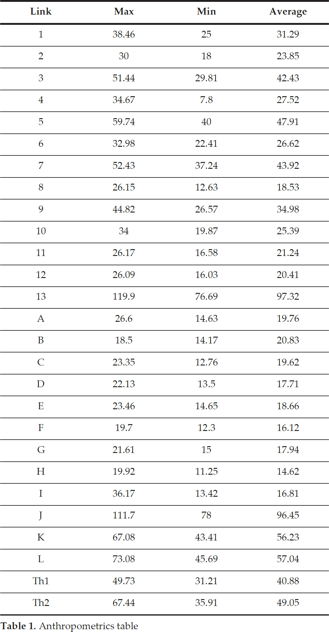
An anthropometric study of the hand was conducted from a population sample of 500 people to determine ideal exoskeletal size. This sample comprised 70 males and 30 females aged between 16-70 years old, all of whom were Mexican. Table 1 shows the maximum, minimum and average results for each part of the hand.
Anthropometrics table
3. Mechanical Design
The main objective of the mechanical design is to achieve independent movement in each of the phalanges of the hand. This assists the patient to adapt the exoskeleton to their own hand deformity. As such, this system is completely adjustable to the different anthropometries and deformities that may occur in the hand's fingers.
ExoK'ab contains six DOF in each of the hand's fingers (numbers 1 to 6). The first movement (1) is a prismatic displacement. DOF (2) is an abduction-adduction movement (it is not actuated); the DOFs (3) and (4) correspond to a rotational movement for flexion of the proximal and distal phalange. Movement (5) corresponds to the telescopic movement of the proximal and medial phalanges. This mechanism was specifically designed to not generate independent movements in the phalanges and as such, indicates a distinctive and desirable feature. The mechanical design of the finger transmission is shown in Figure 3 and presents: (1) the linear displacement mechanism; (2) the abduction-adduction mechanism; (3) the gear for flexion-extension movement; (4) the straight gear for flexion-extension of the medial phalange; (5) the telescope mechanism for carrying out the flexion movement of the phalange; (6) the proximal, (7) distal and (8) cylindrical axis mechanism for linear displacement. Figure 4 shows the elements of the mechanical system that perform each phalange movement. These elements are: worm screws (8) and (9) and the straight gear of the flexion-extension proximal phalange (3) and (4). The motors are placed in (10) and (11), and the position of the sensor for measuring the rotation of each phalange is coupled to the axis in gears (3) and (4); the FlexiForce force sensors are placed in (5) and (6).

Mechanical design of the phalanges' transmission

Mechanical design of the phalanges' transmission
The worm gear mechanism uses a DC motor with 5 kg-cm of torque and a 100 rpm rotational speed. The output speed of the mechanism was designed to rotate 97.2° in one second. In order to obtain this rotational speed in the phalanges of the exoskeleton, the worm gear was calculated with 12 teeth (2 teeth in contact between gears) and an output speed of 16.66 rpm. The relation ratio in the mechanism is 1/6.
The kinematics schema of the mechanism is shown in Figure 5, where the Ji is joint number, di is distance between the axis of the phalange and the flexion rotation point of the exoskeleton, Si is joint linear displacement, qi is joint angular displacement, ri is the radius of the gear,

Kinematics schema
Despite the complexity of the mechanism, ExoK'ab includes force and position sensors mounted in each phalange to generate a force-position control, thereby allowing the therapist to define rehabilitation routines based on a variety of user requirements. Moreover, the complete phalanges system is supported on a light-weight base mould and developed based on a clinically supervised hand anthropometric study, and includes an adjustable wrist for reaching a greater population of patients without limiting performance (see Figure 6).

Design of the hand exoskeleton base
The base mould also supports the transmission mechanism per phalange, which has the capacity to adjust to different knuckle distances for different users. Figure 7 shows the adjusting mechanism of the wrist, where the guide duct for the electronic wiring is shown. Figure 8 shows the exoskeleton weight in grams, as well as the palmar view of the designed mechanism, where it is possible to see the DC motors.

Adjustable bracelet mechanism
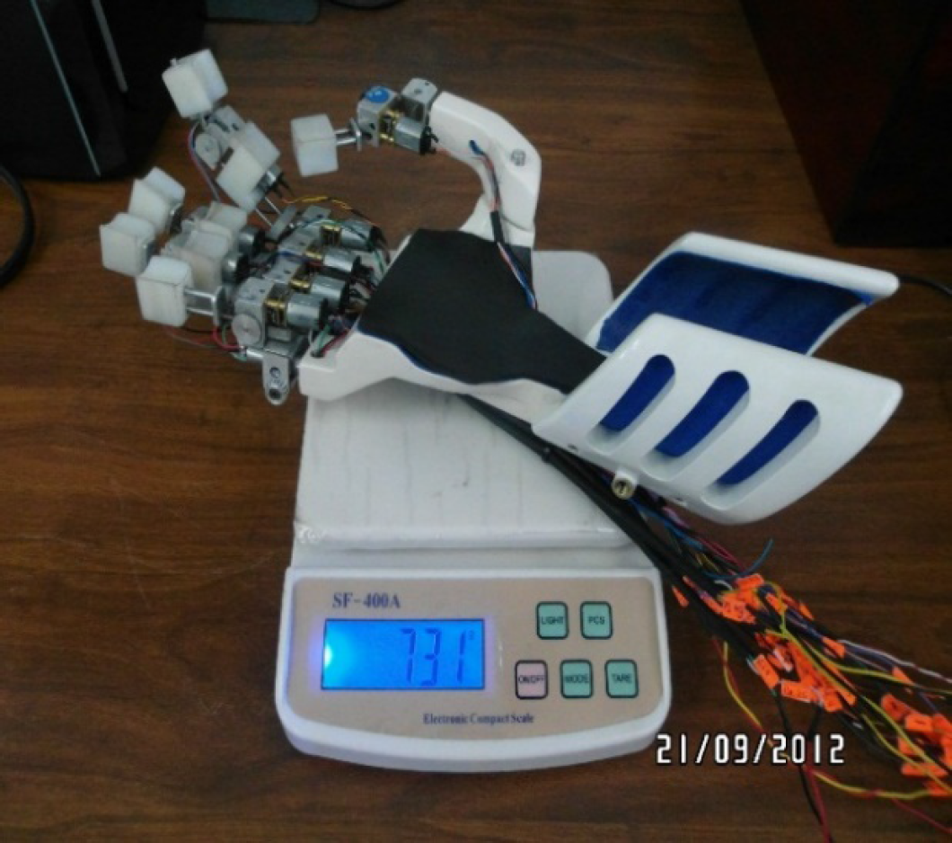
Rear part and weight of the exoskeleton
The hand exoskeleton assemblage presented in Figure 9 shows the displacement mechanism of the proximal phalanges, the gearwheel boxes, the linear and rotational potentiometers and the DC motors, which provide the necessary rotation to the fingers' flexion movement for achieving the entire measurement of the hand force. Achieving this is a significant challenge and as such, it is essential that a controlled feedback state is implemented at the kinematic or dynamic level. Therefore, a mechanism where sensors are placed at the top part of the phalanges for ergonomic and maintenance purposes was designed for obtaining the correct placement of the force sensors.
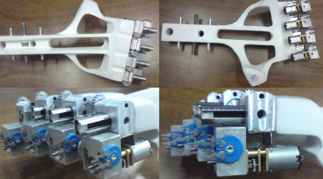
Proximal phalange mechanism assembly
Additionally, a Velcro ring that integrates a cylindrical die of 1 cm in diameter, made of stainless steel, was used to obtain the effect of the pressure applied on the force sensor. This ring is located in the upper part of the force sensor in such a way that the metallic pad presses it against the upper part of the phalanges support. Hence, when the user applies flexion movement in their hand, the metallic pad transmits the pressure to the force sensor via the Velcro ring, which is used as the control signal and the modulator of pressure and force effected by the commanding joint displacements.
The mechanical design of this exoskeleton was specifically designed for passive and active rehabilitation. On the one hand, in terms of passive rehabilitation, the mechanical displacement of each finger of this robot ensures the correct adjustment between the exoskeleton and the human finger.
For this reason, it was important to measure all rotational and translational movements of each part of the mechanism. On the other hand, for active rehabilitation, one of the goals of this exoskeleton was to reduce the effects of having a high transmission ratio due to the worm screws. Therefore, force sensors were mounted in each phalange in order to measure the quantity of force that the user applies in each phalange. Since the objective was to apply a force-position control in each phalange, the user must carry out a certain quantity of force in each phalange of the exoskeleton to achieve the force goals indicated by a physiotherapist. In other words, during their rehabilitation routines, users will perceive each phalange to have spring behaviour, indicating a direct relationship between force and position in the phalanges.
4. Electronic Design
The electronic system was designed for controlling 10 DC motors and for measuring 10 force, 10 angular position and four linear position sensors. A motherboard is responsible for integrating and obtaining data delivered by the signal acquisition and processing target (shown in Figure 10). The power control target controls the position of 10 DC motors and is isolated using integrated circuits with 10 optocouplers (PS2801-4-A).
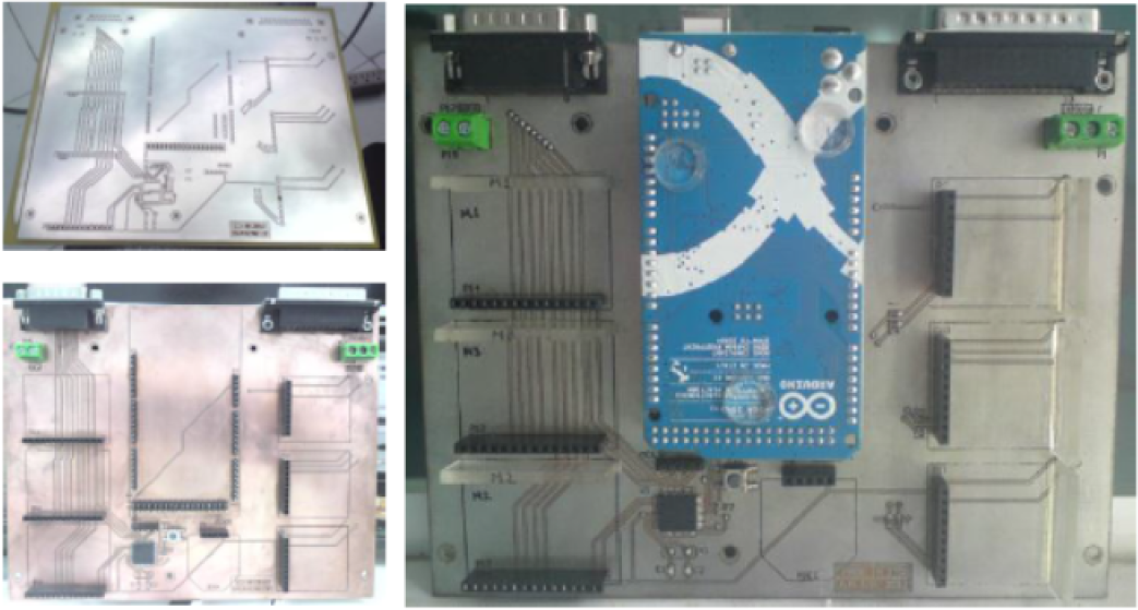
Motherboard PCB design
Each optocoupler is responsible for receiving a PWM signal from the Arduino microcontroller and supplying it to the power stage. For the power electronics section, motor drivers (L298N) were employed and each L298N circuit took over two H-bridges to control two motors.
The position sensors (shown in Figure 11) are important for the kinematics of the robot. This device has three sensors per finger, two potentiometers with rotatory motion and one potentiometer with slider movement. The potentiometers used were analysed by executing destructive tests in order to validate their lifetime and stability.

Sensor positions
ExoK'ab uses a flexi-force sensor. The point where patient-system interaction is located varies resistance according to the applied force, because sensing force is a critical stage and requires efficient measurement. Nonetheless, this system is not completely stable, because it presents different disadvantages in terms of resolution, stability, repeatability, hysteresis and drift. Therefore, a special electronic system for detecting the variation of capacitance according to the applied force was designed. The system uses a resistive force sensor as a generator for a frequency signal, which is executed by an oscillator system that shows the capacitive qualities of the sensor [22]. Figure 12 shows the circuit applied for the force sensor.

Force sensor circuit
Figure 13 indicates the position of these force sensors. The red band connects the fingers to the exoskeleton and this connection is responsible for transmitting force from the human fingers to the exoskeleton sensor.

Force sensors
5. Integration of the System
The entire system consists of mechanical parts, position and force sensors, control targets and power electronic targets and actuators; its integration is shown in Figure 14.
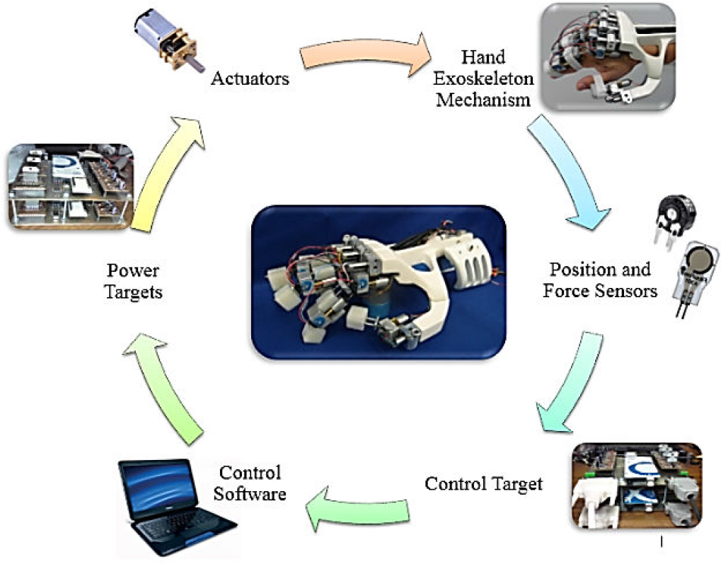
Integration of the system
6. Forward Kinematics
The kinematic model is obtained from the 4-DOF finger mechanism, which involves one prismatic and three rotational DOFs (see Figure 15). Table 2 shows the Denavit-Hartenberg (D-H) convention used, where parameters allow for obtaining the inverse and forward models.

Direct kinematics model for the finger
D-H parameters

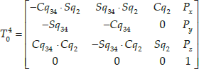
where
7. Workspace
To determine the end effector position in operational and generalized coordinates on their own reference frames, forward and inverse kinematic models were employed. Figures 16 and 17 suggest that the best regions for energy and work conversion are in the region where maximum eigenvalues of the Jacobian can be found, including the proximal and intermediate movement of 1.5708 rad.

Top view workspace q2 (−0.26 rad to 0.26 rad)

3D view workspace q2 (−0.26 rad to 0.26 rad) q3 (1.57 rad), q4 (1.92 rad)
8. Inverse Kinematics
To obtain the inverse kinematics of the robot a geometric method was implemented and is shown in Figure 18.

Inverse kinematics configuration
Consider that q1 and q2 are not actuated movements. The points of interest are P1, P2 y P3 9 (see Figure 18) and are given by:

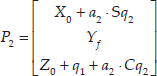

The distance r defined between P1 y Pf is:

A simplified diagram of the inverse kinematics configuration (Figure 18) was obtained, where:


9. Analytic Jacobian
The analytic Jacobian was obtained using the geometric Jacobian using the following standard formula:

Using conventional roll, pitch and yaw (RPY) representation, where


This yields a 6×4 matrix in which the first three rows correspond to lineal velocity and the three bottom rows correspond to rotational velocity.

The inverse Jacobian renders the differential kinematics map, i.e., it maps x, which represents the lineal and rotational velocities of the end effector Cartesian space (xyz) into generalized velocities, and is expressed as follows:

where:

Since J a is not square (6×4), the left Jacobian pseudo-inverse is used to compute each motor's desired joint velocity, which corresponds to the desired position and velocities of operational coordinates. This is useful when a velocity command is preferred over a torque or force control at torque/current level.
10. Position Control and Orientation
Once the inverse analytic Jacobian is obtained, the position and orientation proportional control (P) is implemented; a block diagram regarding this process is shown in Figure 19.
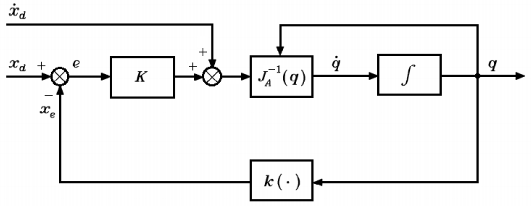
Block diagram of the position and orientation control
where

Position of the end effector
11. Force-position Control
Geometric Jacobian J is used to properly map the desired torques τd into force

where:
The vector of desired forces fd is given by the force variables
12. Experiments and Discussion
Passive rehabilitation is one of the first procedures in rehabilitation after suffering an injury such as broken bones. Following on, the therapist is responsible for assisting the patient in the movement of all phalanges using flexion and extension movements. At this point, it is important to point out that broken bones in the hand result in muscle atrophy and stiffness. Therefore, therapists have to evaluate the flexion and extension range in each phalange of each finger in the patient first and then, effect repetitive movements in the range previously selected in order to aid the patient in incrementing the range of movements gradually. Although this may seem like a simple procedure, it is complicated due to physiotherapists never knowing exactly if the movement ranges effectuated on the patient are correct. All of the above generates painful and not particularly efficient rehabilitation routines.
12.1. Passive rehabilitation
The experiment was implemented involving 10 patients divided into two groups of five people each (two women and three men). The 10 patients were selected according to a specific characteristic: having suffered a wrist fracture, resulting in muscular atrophy and a similar range of movement in the phalanges. In group 1, the rehabilitation routines were directly performed by the physiotherapist while in group 2, the rehabilitation routines were carried out using the exoskeleton. The objective of the experiment was to evaluate performance and evolution related to the range of movement of patients during three weeks of rehabilitation.
The patients of group 1 used an electronic glove especially designed for measuring the position and angles of the different phalanges of the hand, using 12 flexion sensors placed in each joint of the fingers with a precision of +/- 0.0227 rad. The physiotherapist assisted the patients of group 1 with movements of flexion and extension of 0.349 rad in each phalange of the hand over three sessions a week, each session lasting 10 minutes. In the second week, the movement executed was 0.698 rad and in the third week this was 0.959 rad. The patients of group 2 used the exoskeleton, which had previously been programmed by the physiotherapist with flexion and extension movement routines; these specifics were repeated for group 1. After each 10 minute session, patients were requested to flex and extend all the fingers of their hands as much as possible until they began to experience pain.
Figure 21 shows the passive rehabilitation routines of one of the patients using the ExoK'ab device. The simulated plots indicate the desired motion of the phalanges and the real plots indicate the motion of the robot. Figure 22 shows a passive rehabilitation routine during flexion and extension movements.
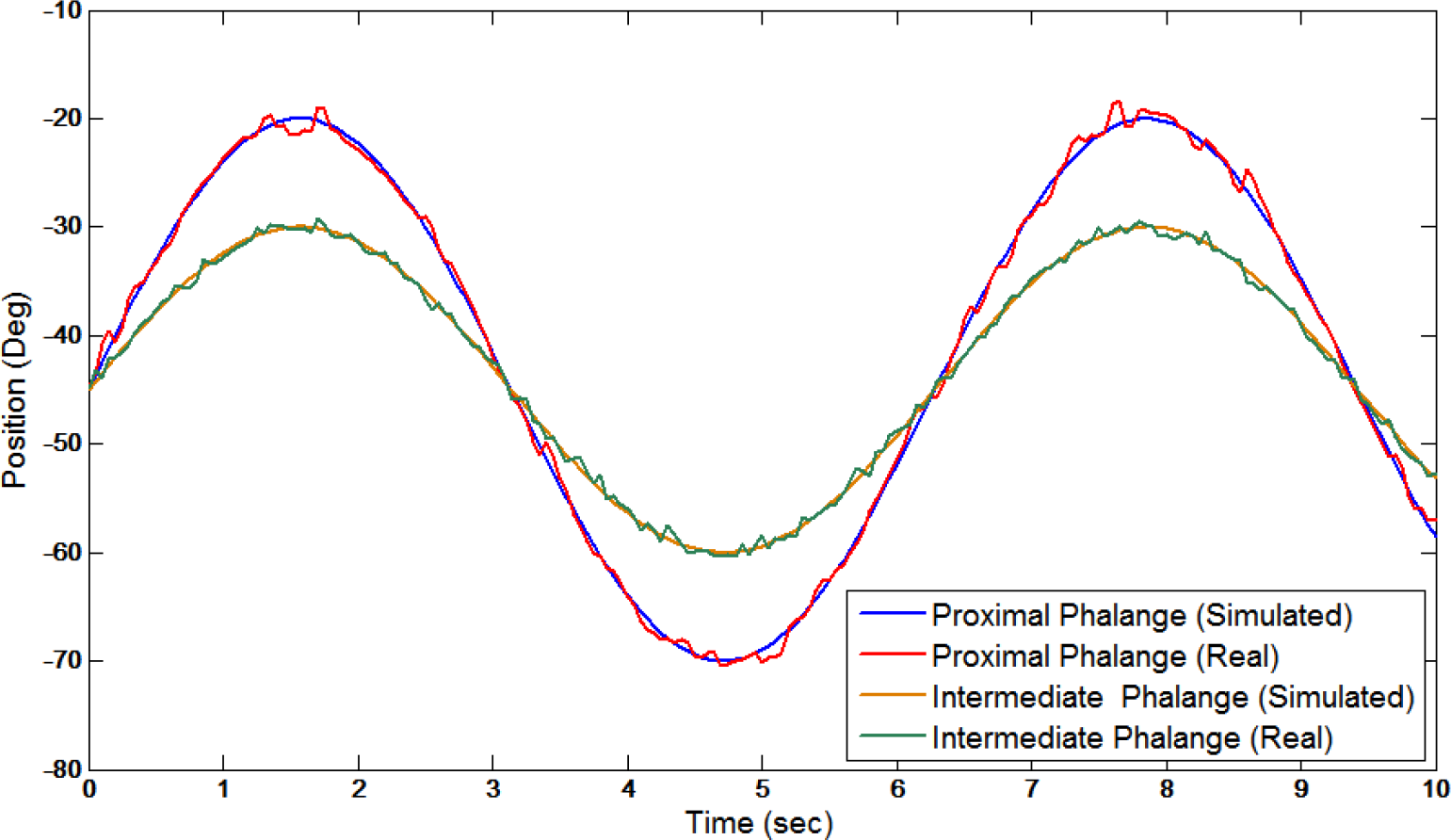
Passive rehabilitation routine of one patient using the ExoK'ab

Passive rehabilitation routine during flexion and extension movements
12.2. Active rehabilitation
Active rehabilitation is important for improving the grasping force of patients. This experiment was effected among the same individuals involved in the previous experiment (passive rehabilitation). In group 1, the active rehabilitation routines were carried out by a conventional hand exercise table, with hanging weights that are connected to the fingers of the patients using cables and pulleys. The patients of group 1 performed flexion and extension movements without any help, using during the first week a weight of 0.2 kg for each finger during four sessions of three minutes per day, three times a week. In the second week, a weight of 0.4 kg was used and finally, in the third week, a weight of 0.6 kg was applied. In order to obtain information about the performance from the user, it was necessary to use the same force sensors applied in the exoskeleton, but in this instance, connected to the phalanges on the individuals in the test group. For group 2, the hand exoskeleton was mounted on the patient's hand during active rehabilitation. The force-position control of the robot was programmed (depending on the week of rehabilitation) at 0.2 kg, 0.4 kg and 0.6 kg for each finger. In the phase of active rehabilitation, one patient noted that he felt the exoskeleton work like a spring, where it moved when the desired force on the phalanges was reached; alternatively, when the patient could not reach the force expected, the exoskeleton returned to the initial position. Patients in group 2 performed flexion and extension movement using 0.2 kg, 0.4 kg and 0.6 kg for each finger during four sessions of three minutes a day, three times a week during three weeks, the same as for group 1. Figure 23 shows the active rehabilitation routines of one patient. The range of force achieved for each phalange is also observed.
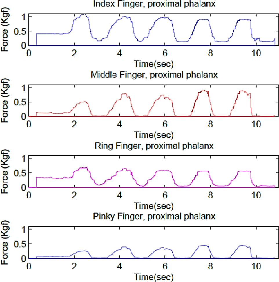
Routines of force-position carried out by the patient
During the active rehabilitation routines, the user interacts with virtual environments using the XVR software. During this interaction, the user must squeeze a virtual planet using the force indicated by the therapist in order to pass the planet through a virtual ring. Figures 24 and 25 show the virtual environment in which the patients interact [23].
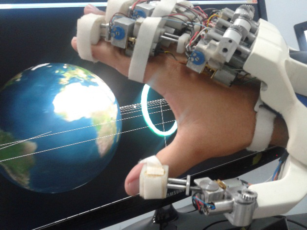
Extension movement

Flexion movement
The results presented in Table 3 show the averaged force of flexion for the proximal and intermediate phalanges obtained by the 10 patients divided into two groups. For group 1, the range of force was below expectations; this was due to the hand exercise table not limiting the movement of the arm and when the patients were completing the exercise, they unconsciously moved the arm in order to gain extra help. It is clear that those in group 2 achieved a force near the desired range. Moreover, the use of virtual reality rendered the exercise less tedious for the patients involved.
Average force of flexion for the proximal and intermediate phalanges obtained by 10 patients

13. Discussion and Conclusion
This paper presents the mechanical and electronic design of a novel rehabilitation hand exoskeleton according to therapist specifications. The purpose of the presented design was to obtain full feedback capabilities from a light-weight and low-cost solution. To achieve this, a preliminary hand anthropometric study was also presented. This study was necessary to establish the correct design criteria that led to a specific mechanical structure, capable of exerting forces within the range of a typical rehabilitation routine and facilitating wearing by anthropometrically different user hands. In addition, the design presented in this paper introduces the kinematic study of and control algorithms implemented in the specific design, as well as electronic solutions for acquiring sensor signals and actuating embedded motors. To complete the experiment, active and passive rehabilitation routines were conducted and compared with traditional rehabilitation methods in order to evaluate the effectiveness of this novel solution. While analyzing experimental results, the advantages of using this exoskeleton as part of the rehabilitation process were observed. Its controlled force allows for having more control on exerted forces during therapy routines, which leads to less involuntary injuries due to over-applied force when performing rehabilitation exercises. Position control helps the therapist to restrain patient movements as an effective approach for avoiding pain due to over- flexion-extension movements that can occur in normal routines performed by a therapist. Finally, the addition of a graphical interface helps to motivate the patient to perform their routines with additional effort.