
Abstract
Docking design of self-reconfigurable robots is studied. Firstly, the self-reconfigurable robot is presented. Its basic module is designed, which is composed of a central cube and six rotary arms. Then, the novel docking mechanism of each module is designed. It is critical for the self-reconfigurable robot to discard any faulty modules for the self-repairing actions. The docking process is analyzed with the geometric method. The docking forces between two modules are described with the static equilibrium condition and the small motion's method. It shows that the reliability of the connection will be increased when the module's weight G is increased. It is important to finish the docking action in the self-reconfigurable robot. At last, a simulation of six-module and an experiment of three-module show that the modules can finish the docking process effectively.
Introduction
Self-reconfigurable modular robots (SMR) consist of a set of standardized electromechanical modules which can dynamically change their geometrical shape to complete different requirements of various tasks. They are more versatile, flexible, and capable than fixed-morphology robots. They can work in unstructured and unpredictable environments, such as the space and deep-sea exploration, rescue operations in earthquake areas.
The SMR can be classified into the lattice-type and the chain-type. Chain-type self-reconfigurable robots, such as the cubic modules (Polybot) (Yim, M., Zhang, Y., etc, 2002), the tetrahedral and octahedral modules (Tetrobot) (Hamlin, G. J., & Sanderson, A. C., 1998), CONRO (Castano, A., Behar, A. & Will, P., 2002), have a higher degree of mobility than that of lattice-type systems. Lattice-type robots, on the other hand, can easily self-reconfigure and are suitable for forming various static configurations, but they have difficulty in generating motion, such as a cubic structure (3-D self-reconfigurable mechanical system) (Murata, S., Yoshida, E., etc, 2001), Fracta 3D (Murata, S., Kurakawa, H., etc, 1998), two hemispheres joined modules (ATRON) (Christensen, D. J., & Stoy, K., 2006), Telecube (Suh, J. W., Homans, S. B., & Yim, M. H., 2002), the crystal module (Crystalline) (Bulter, Z., & Rus, D., 2003), the “I-Cube” modules (I-Cube) (Unsal, C., & Khosla, P. K., 2000), the double-cube modules (Molecule) (Kotay, K. & Rus, D., 2005), the rhombic dodecahedron modules (Proteo) (Yim, M., Zhang, Y., etc, 2001), two semi-cylindrical parts (M-TRAN) (Kurokawa, H., Tomita, K., 2008) and M-Cube(Fei, Y.Q., & Zhao, X.F., 2007), (Fei, Y.Q., Zhu, Y.L., & Xia, P., 2009).
For self-reconfigurable robots, one of the most important features is its self-repairing function (Christensen, D. J., 2007). It means that the robot has the ability to detect and recover from failures. When some modules of the robot fail, the robot can discard them and replace them with spare modules to keep the completeness of the configuration. This feature is unique compared with the fixed-morphology robot. However, it's common in biological systems. It inspires us to develop a novel mechanism which has the self-repairing capability. For the self-reconfigurable robots, it is important to design and analyze their docking mechanism to make them have the self-repairing capability.
In this paper, we describe the configuration of a 3-D, like the cubic shape, homogeneous and lattice SMR. Its mechanical structure is presented, which can finish self-repairing actions when faulty modules appear. The docking mechanism is designed and the docking process is analyzed with the geometrical method. The docking forces between two modules are described.
Module Hardware
Structure of module
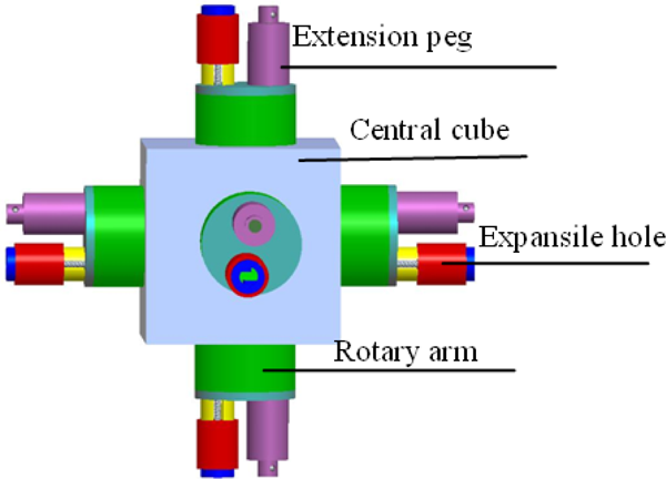
The self-reconfigurable modular robot “M-Cubes” (Modular-Cubes) is proposed (Fig. 1). Its structure and the docking mechanism are different from those of Fracta 3D (Murata, S., Kurakawa, H., etc, 1998). Each module in M-Cubes is composed of a central cube and six rotary arms which are distributed on the six sides of the central cube (Fei, Y.Q., & Zhao, X.F., 2007). Each rotary arm has a connection peg and a connection hole. The connection peg has a locking system, which can lock the connection when the connection peg inserts into the other module's connection hole. Then, two modules can connect to each other firmly. The connection arms can rotate along their axes. In the central cube (Fig. 2), there's the DC motor, which is the power supply of the connection arms. The rotation of the motor is transmitted to the six output axes only by one two-gear reducer and five cone-shaped gears.

M-Cubes module.

Inner mechanics of M-Cubes module.
There's one clutch on each output axis to control whether the connection arm should rotate or not. Figure 3 shows the inner mechanism of each module in detail. It mainly consists of one DC motor, one small gear, one big gear, one transmission shaft, three big cone-shaped gears, six output axes, two small cone-shaped gears. Thus, the motion transmission of each module can be obtained in Fig. 4.

The mechanism of each module.

The motion transmission of each module. 2.2 Docking mechanism
1—DC motor, 2—Small gear, 3—Big gear, 4—Transmission shaft, 5—Big cone-shaped gear, 6—Output axis 1, 7—Big cone-shaped gear, 8—Big cone-shaped gear, 9—Output axis 2, 10—Small cone-shaped gear, 11—Output axis 3, 12—Output axis 4, 13—Small cone-shaped gear
The docking mechanism is one of the crucial components of a reconnectable module. Due to the unique features of self-reconfigurable robots, such a mechanism must be power efficient, reliable, compact and flexible to operate. The size of the cube is 20cm. Each rotary arm (Fig. 1, Fig. 2.) can connect with/disconnect from other modules. When the robot needs to finish the self-morphing or the self-repairing action, the docking mechanism can finish connecting with or disconnecting from its neighboring module. Especially, when a faulty module appears, the docking mechanism can finish the self-repairing action without others’ help. If a module is damaged, its neighbors should be able to disconnect from the system without any constraints. For the purpose, it is important to design the novel docking mechanism, which allows disconnection to be accomplished at either side of the connection. It is critical for the self-reconfigurable robot to discard any faulty modules for the self-repairing action. Figure 5 shows the novel docking mechanism of the module. Each rotary arm consists of one expansile hole (connection hole) (Fig. 6) and one extension peg (connection peg) (Fig. 7). The expansile hole mainly consists of two connecting grippers, one cover, one sleeve, one track and one screw rod (Fig. 6 c). The hole can open and change its shape when its neighboring module is damaged and it needs to disconnect from the faulty module and finish the self-repairing action. Generally, the hole keeps the closed state (Fig. 6 a). When the connection/disconnection appears among normal modules, the expansile hole does not open. When the normal module wants to disconnect from the faulty module, the hole of the normal module is open (Fig. 6 b) and disconnects from the faulty module. Then, this hole returns to its closed state again. When the normal module wants to connect to the faulty module, the hole of the normal module is open and connects to the faulty module. Then, this hole returns to its closed state again.
The diagram of M-Cubes module.
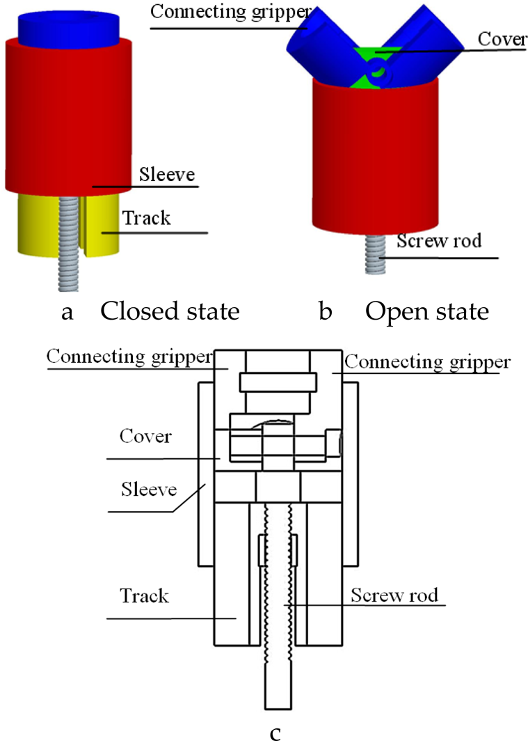
The structure of one expansile hole.

The diagram of one extension peg.
The extension peg mainly consists of three beads, one pin, one shell and one piston (Fig. 7 b). The hole can accept and lock the incoming peg by meanings of beads. The hole can release a lock by releasing the beads of the normal module or open the hole when its neighboring module is damaged.
Figure 8 shows the disconnecting process of the normal module and the faulty module in the self-repairing action: when the module is damanged, it doesn't work. It should be substituted by a spare module. Thus, its neighboring normal module disconnects from the faulty module, the hole of the normal module is open and disconnects from the faulty module. Then, this open hole returns to its closed state again. The faulty module is discarded and the spare module is used to finish the self-repairing action. The self-repairing action of a multi-module system is shown in Fig. 9. In order to keep the completeness of the robot configuration, the system discard the faulty module (Fig. 9 b). Then, the vacant position is filled by a spare module (Fig. 9 c). The self-repairing task is finished.

Disconnecting process of the normal module and the faulty module.

Self-repairing action of a multi-module system 3. Three-module Motion Rule
3. Three-module motion rule
According to the geometric feature of the self-reconfigurable robot, three-module motion is a basic motion for the lattice self-reconfigurable robots. Three-module motion can really change the positions of the modules. Three modules are named as follows: a base module, a rotary module and a motion module. The motor of the base module works. Then the motion module rotates along the rotary arms of the base module and the rotary module (Fig. 10).

Three-module motion 4. Docking Process
The docking is a crucial action for self-reconfigurable robots. In the lattice self-reconfigurable robot, a successful docking action consists of at least three integrated complex stages. First, one action that is frequently used in the docking process is to move a module on a given trajectory and rotate

Rotary process of modules

Connection of one peg and one hole.
The undocking is an inverse process of the docking. When the robot decides to disconnect from an existing connection, it releases the latching mechanism by pegs.
In fact, the docking process is that one peg of module i inserts into one hole of module j, and at the same time one peg of module j inserts into one hole of module i. It is a complex multiple peg-in-hole process.
In the paper, two dimensional problems are discussed. The geometrical models of one peg and one hole in module i and module j are shown in Fig. 13. There is the tilt angle θ between two modules. The boundary state of the docking is shown in Fig. 14. Its geometrical constraint is

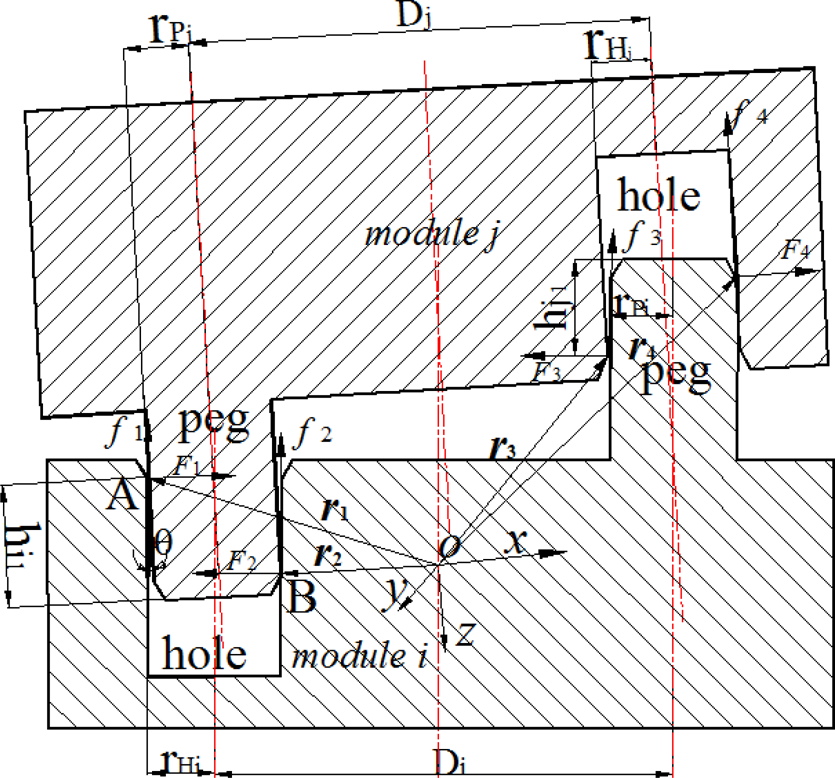
The geometrical models of the docking in module i and module j.

Boundary state of the docking.
When θ is more than θ0, two modules cannot align.
Pegs cannot insert into holes. They cannot finish the docking process. So, the tilt angle must be adjusted to make

The geometrical constraint of the two-point contact state in the right peg and the right hole is

The dimensions of two modules are the same. We can obtain

Thus, hi1 = hi2, there are two-point contact states in the right peg and the right hole. Thus, there are at most four-point contact states in two modules’ docking. The pose of the motion module should be adjusted and the tilt angle should be reduced to avoid appearing contact states.
Where hi1 is an insertion depth of the left peg (module M j ) into the left hole (module M i ); hj1 is an insertion depth of the right peg (module M i ) into the right hole (module M j ). The peg of module Mj has a radius of rPj, whereas the peg of module M i has a radius of rPj. The radii of one hole in module Mi and one hole in module M j are rHi and rHj, respectively. θ and θ0 are angles between the axis of a peg and that of a hole. D i , Dj represent the distance between the peg's axis and the hole's axis of module Mi, module M j , respectively.
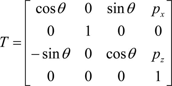
The coordinate system (oxyz) is set up at the center of each module (y = z×x) (Fig. 13). In the coordinate system oxyz, the vectors
The wrenches of the contact cases are described as follows


According to Fig. 13, the following formulas can be obtained


where g represents all contact states, g = 1,2,3,4; q represents the docking state, q = 1,3; m represents the docking state, m = 2,4.
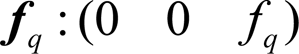
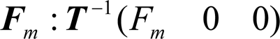
The wrenches of the forces are as follows,
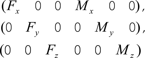
Here F x , F y , F z , M x , M y , M z represent the measured forces and moments in the coordinate system (xyz).
The application of the static equilibrium condition results to the following equations,


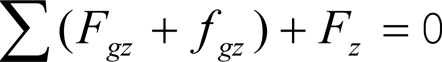

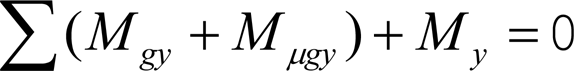

In two dimensions, when there are four contact points (Fig. 13), the formed system of equations is redundant. The unknown variables are five, while the available equations are four. To overcome this problem, we improve the method about the small motions of the peg around the contact points (Tsaprounis, C. J. & Aspragathos, N., 1998).
For the contact point B on the left peg-in-hole, the angle between the force vector F2 and the x-axis is θ. Let the direction of the k-axis be the same as that of the force vector F2. The k′-axis is vertical to the k-axis. A translation is δk along the k-axis and a rotation is δϕ about the k′-axis due to δs. δs is a unit displacement at the contact point.

The following equations can be obtained
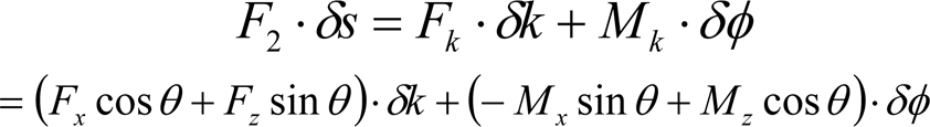

Solving equations (21)(23), F2 can be obtained

where H is the length of the peg, g tk is the gain of the sensor in tension in the k-axis direction; g Tk , is the gain of the sensor in torsion in the k′-axis direction.
So, the expressions of the contact forces can be shown simply. From the above expressions, we know that the docking process of two modules is a complex multiple peg-in-hole process. According to the force/moment, the pose of the motion module and the driven force can be adjusted to make two modules align and finish docking.
According to the motion rules of lattice self-reconfigurable robots, after two modules align and finish docking, one module can at least lift two modules to rotate along their rotary arms. Assume the modules move slowly. The maximal output torque H of the motor is

Where i is the reduction ratio, G stands for the gravity of the module, η is coefficient of safety, n is the number of the modules, l is the distance between centers of two neighboring modules.
Thus, Maxon RE35 DC motor is used to make modules work. Its reduction ratio is 156.
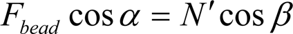
The worst part is two docking rotary arms. As the rotary arm has a connection peg and a connection hole, we give the locking force analysis of the vertical connections. Figure 12 shows the connection of one peg and oen hole after the peg-in-hole action has been finished. Figure 15 shows the force analysis of the pin, the bead and the hole when two modules connect to each other in the vertical direction. Since Fig. 15 gives the condition of only one bead with the hole and the pin, we make the force triple. Here β stands for the chamfering of the pin, N stands for the pin's pressure from one bead, N′ stands for one bead's pressure from the pin. Thus


Force diagram of the pin, the ball and the hole.
F
pull
stands for the pressure on the pin F
support
stands for the bearing capacity of one bead, F
bead
stands for the resultant force of the pressure on the hole from one bead, α stands for the angle between the direction of the horizontal axis and that of the resultant force,


From the equations (26) to (31), it can be obtained
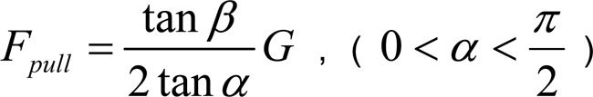
From the equation (32), when G is constant, α is maximum, F
pull
is the minimum pull force on the pin. From the equation (29), the vector sum of N' and F
support
is F
bead
. It shows that N' of the connection is also used to balance G. For this connection, when G is increased, both F
pull
and
Simulation
Under condition that gravity, friction, inertia are negligible, the simulation of the docking process on a six-module system is shown in Fig. 16. First, the module 2 connects to the module 4 and the module 1 connects to the module 2. The module 1 disconnects from the module 3 (Fig. 16 a). The module 2 rotates 90° around its center line and the module 1 moves to the other position (Fig. 16 b). Then, the module 1 and the module 6 finish their docking process (Fig. 16 c). When they finish their docking action, the module 2 disconnects from the module 4. The module 2 and the module 1 rotate 90° around the docking axis of the module 1 and the module 6. Thus, the module 2 moves to the other position (Fig. 16 d). The connection and the disconnection between modules are finished.
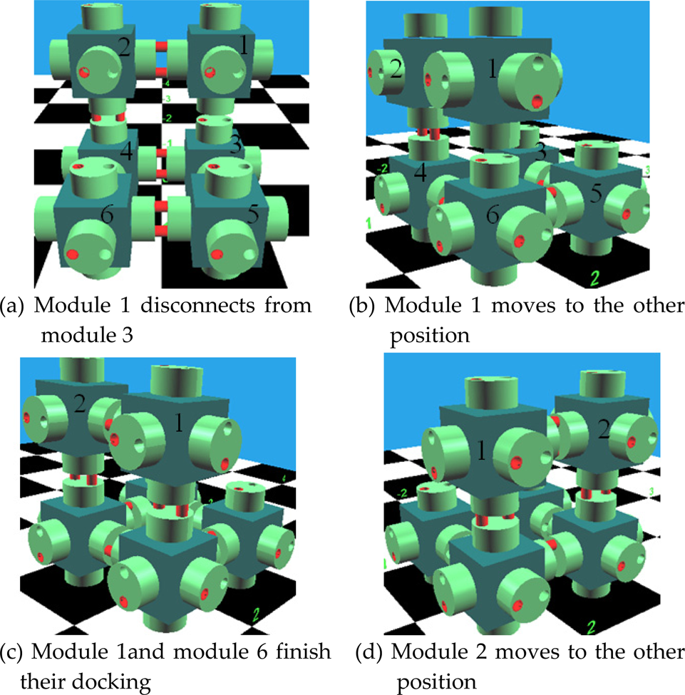
Simulation of the docking process on a six-module system 6.2 Experiment
In Fig. 17, the lattice self-reconfigurable modular robot consists of a base and three modules. In Fig. 17 a, the module 1 connects to the base. Its docking mechanism works. After the module 2 connects to the module 1 and the module 3, the module 2 and the module 3 disconnect from the base. The arm of the module 1 that connects to the module 2 rotates along its own axis so that the module 2 rotates with it, too. Because the module 2 has a firm connection to the module 3 by one of its arms, the module 3 rotates as well. Consequently, the position of the module 3 is changed, while the positions of the module 2 and the module 1 remain the same as before (Fig. 17 b). The docking process of three modules is finished.

Modules’ docking and rotation.
In this paper, the lattice self-reconfigurable robot is designed, which can finish the self-repairing action when the faulty module appears. Each module consists of the central cube and six rotary arms. A novel docking mechanism is presented. Each connection/disconnection side consists of one expansile hole and one extension peg. Then, the states of the docking and constraint between two modules are analyzed with the geometrical method. The contact forces and the locking force of the docking process are described with the static equilibrium condition and the small motion's method. It shows that the reliability of the connection will be increased when the module's weight G is increased. At last, a simulation of six-module shows that the modules can finish the docking process effectively. And a self-reconfigurable robot consisting of three modules and a base, which performs the connection, disconnection and rotation, shows the above analysis effectively.
Footnotes
8.
This work is supported by NSFC Grant 50775145, 51075272.