
Abstract
Rather than the conventional classification method, we propose to divide modular and reconfigurable robots into intra-, inter-, and nested reconfigurations. We suggest designing the robot with nested reconfigurability, which utilizes individual robots with intra-reconfigurability capable of combining with other homogeneous/heterogeneous robots (inter-reconfigurability). The objective of this approach is to generate more complex morphologies for performing specific tasks that are far from the capabilities of a single module or to respond to programmable assembly requirements. In this paper, we discuss the theory, concept, and initial mechanical design of Hinged-Tetro, a self-reconfigurable module conceived for the study of nested reconfiguration. Hinged-Tetro is a mobile robot that uses the principle of hinged dissection of polyominoes to transform itself into any of the seven one-sided tetrominoes in a straightforward way. The robot can also combine with other modules for shaping complex structures or giving rise to a robot with new capabilities. Finally, the validation experiments verify the nested reconfigurability of Hinged-Tetro. Extensive tests and analyses of intra-reconfiguration are provided in terms of energy and time consumptions. Experiments using two robots validate the inter-reconfigur ability of the proposed module.
Introduction
The design philosophy of reconfigurability has been studied and applied to robotics since the 1980s. A number of reconfigurable robotic systems have been proposed thereafter [1, 2, 3]. Many practical applications prove that reconfigurability is a very valuable design strategy. Conventionally, these reconfigurable robots are classified into lattice, chain, and hybrid types [4, 5]. From another perspective, we propose a new classification of these existing robots. To this end, we introduce a concept, namely nested reconfiguration, which is an integration of two typical classes: intra-reconfiguration and inter-reconfiguration. Hence, we can classify the modular and reconfigurable robots into intra-, inter-, and nested reconfigurable types.
An intra-reconfigurable robot can be viewed as a collection of components (sensors, actuators, mechanical parts, power, controller, etc.) acting as a single entity while having the ability to change its internal morphology without requiring any external assembly or disassembly. Figure 1 presents a conceptual depiction of intra-reconfigurable robots. Intra-reconfigurability has been generally centred on functional modules, namely motion, sensing, and control. Intra-reconfiguration for motion allows robots the flexibility of traversing over a variety of terrains and spaces (land, air, and water) as well as a series of manipulation skills. Examples include versatile amphibious robots capable of intra-reconfiguration between terrestrial and aquatic gait mechanisms [6], metamorphic robotic hands capable of intra-reconfigura-ble palm topologies [7], and reconfigurable walking mechanisms that produce a wide variety of gait cycles [8]. Intra-reconfiguration for sensing enables a robot to adapt its sensor configuration to the environment or task at hand. To this end, evolutionary design techniques for perceptual intra-reconfigurability [9, 10] and strategies for recognizing and eliminating corrupted sensory have been proposed [11]. Finally, intra-reconfiguration for computing allows robots to reconfigure control in response to environmental/task demands [12 – 17].

Conceptual depiction of intra-reconfigurability
Except for the reconfiguration happening in the individual robot, multiple robots can also joint together to form a new configuration. Figure 2 presents a conceptual depiction of inter-reconfigurable robots. This inter-reconfigurability has gained widespread popularity in the robotics community due to the possibility of assembling a variety of specialized robots and complex structures using a standard set of components [18]. The inter-reconfigurable robot consists of an congregation of modular homogenous or heterogeneous intelligent components/robots capable of forming a variety of morphologies through an ongoing assembly and disassembly process. Numerous inter-reconfigurable robots have been developed for a variety of potential applications ranging from surveillance to space exploration and using different schemes for module docking and undocking, and all types of reconfiguration which includes manual, semi-manual, and self. Relevant examples include CEBOT, PolyBot, Crystalline, M-TRAN, ATRON, Molecube, CKBot, and many others.

Conceptual depiction of inter-reconfigurability
Integrating the advantages of the intra-reconfigurability and inter-reconfigurability yields nested reconfigurability as shown in Figure 3 with a conceptual depiction. A nested reconfigurable robotic system can be defined as a set of modular robots with individual reconfiguration characteristics (intra-reconfigurability) that combine with other homogeneous/heterogeneous robot modules (inter-reconfigurability). However, the objective of this system is to generate more complex morphologies for performing specific tasks that are far from the capabilities of a single unit or to respond to programmable assembly requirements [19, 20]. The two-level reconfiguration process in a nested reconfigurable robotic system implies several technical challenges in hardware design, planning algorithms, and control strategies.

Conceptual depiction of nested reconfigurability
The distinction between intra- and inter-reconfigurability has been framed previously as assembly and disassembly on macro- and micro- scales, wherein the individual robotic module maintains its morphology as constant when assembled in an aggregate structure [21]. The concept of nested reconfiguration explicitly considers the ability of the modular components at the atomic level to internally transform their morphology without splitting. This can be seen in fact as a generalization of the self-deformation principle used in tensegrity-based cellular robots [22].
Inspired by the Tetris pieces, Hinged-Tetro is proposed in this paper as a showcase of study of nested reconfigurable robots. We discuss the theory, concept, and initial mechanical design of such a robot. Hinged-Tetro is a mobile self-reconfigurable robot module based on the theory of hinged dissection of polyominoes that is able to transform itself into any of the one-sided tetrominoes. The robot is of interest for research in nested reconfiguration because it can easily change its structure and combine with other modules to form new morphologies to accomplish, for instance, manipulation tasks that a single robot could not handle on its own.
The remaining part of this paper is organized as follows. Section 2 introduces the concept of polyominoes with some historical considerations and important results, and presents the idea of hinged dissections of polyominoes, where some statements of relevance for the design of Hinged-Tetro are discussed and proven. Section 3 focuses on the mechanical design of the proposed reconfigurable robot. The prototyping of the robot is described in Section 4. Some preliminary experiments, analysis, potential applications of nested reconfigurable robots are presented in Section 5. Finally, Section 6 concludes the paper and discusses future work.
This section introduces and discusses the polyminoes and hinged dissections. The reconfiguration pattern will be extracted and applied to the design of the nested reconfigurable robot presented in the next section.
Polyominoes
Polyominoes (also called n-ominoes or super-dominoes) are plane geometric figures formed by joining one or more equal squares (cells) edge-to-edge. An example of a polyomino, a 16-omino, is presented in Figure 4(top-left). Since its perimeter (24 units) is not equal to that of its minimal bounding box (20 units), this shape corresponds to a non-convex polyomino. Sets of joined squares with at least one couple of cells connected only at their corners [Figure 4(top-right)] or with edges that do not perfectly match to each other are not considered polyominoes. As Figure 4(bottom-left), the polyomino with a hole is the heptomino with seven squares that the polyomino regions for which may be hollow.
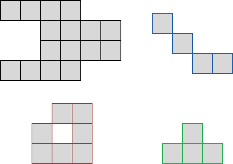
A polyonimo composed of 16 squares, i.e., a 16-omino (top-left). A set of joined squares that is not a polyomino. In general, shapes formed by at least one couple of squares connected only at their corners are not polyominoes (top-right). A polyomino with a hole, a heptomino (bottom-left). A tetromino (bottom-right).
The word polyomino is attributed to Solomon Golomb [23, 24] who seems to be the first mathematician to have treated the subject seriously during his graduate studies at Harvard [25]. Polyominoes can be seen as a generalization of the domino (the two equal squares joined edge-to-edge used in the eponymous board game) to a set of multiple squares. Polyominoes are familiar in popular culture because they have been used as entertainment puzzles since at least the eighteenth century. The rectangular puzzles Jags and Hooks (1785) and Sectional Checkerboard (1880) [26] are classical examples of such practical assembly games.
The problem of estimating the number t(n) of polyominoes composed of n squares [25] has been discussed by several authors since the 1950s. Currently, the best known bound is 3.9856
n
<t(n)<4.6496
n
[27]. This counting is considered in fixed polyominoes, known as lattice animals in statistical physics. In such polyominoes only translation movements are assumed, so two fixed polyominoes are different if they do not have the same orientation. Polyominoes that can be translated and rotated but not reflected are called one-sided polyominoes. Those that can be picked up and flipped are called free polyominoes. The number of free n-ominoes, say r(n), is less than or equal to the number of one-sided n-ominoes, say s(n). In fact, it can be easily shown that
The number of three kinds of polyominoes (n-ominoes, n≤8)

A geometric figure can be dissected into a finite number of smaller pieces that can be rearranged to form another figure [29,30]. For instance, any two simple polygons in the plane (i.e., polygons with non-intersecting sides) of equal area can be dissected by straight line cuts into a finite number of congruent polygonal figures that can be rearranged without overlapping to form the other polygon [31]. This is known as the Wallace-Bolyai-Gerwien theorem [32]. Some popular geometric dissections include the Tangram (the dissection puzzle invented in ancient China), the Hindu problem (the Greek cross dissection into five pieces to form a square [33]), and the Bhaskara's proof of the Pythagorean theorem [34].
Instead of allowing the smaller figures in a dissection to be rearranged arbitrarily, we suppose that the pieces are pin-jointed at their vertices. This special subclass of dissections are called hinged dissections [35]. In 1864, the British mathematician and physicist Phillip Kelland presented what seems to be the first published hinged dissection [30], a proof by rearrangement of the Pythagorean theorem [Figure 5(top)]. For many years, a problem that aroused the interest of several mathematicians was determining if there is always a hinged dissection between two simple polygons, that is, if there exists a collection of geometric shapes hinged at their vertices that can be folded in the plane continuously without self-intersection to form both polygons. Figure 5(bottom) shows a classical example of this problem, the hinged dissection of an equilateral triangle into a square by Henry Dudeney [36]. Recently, Abbott et al. [37] generalized the hinged dissection problem of two polygons and constructively proved that actually any finite collection of polygons of equal area has a common hinged dissection. The following theorem summarizes this result:

Examples of hinged dissections. Kelland's proof of the Pythagorean theorem by a hinged rearrangement (top). Dudeney's hinged dissection of an equilateral triangle into a square (bottom).
Any polyomino can be associated to a polygon. In the case of tetrominoes, for instance, I corresponds to a rectangle, O to a square, and T to an octagon. Theorem 1 implies that there exists at least one hinged dissection of polygons that can be rotated into any n-omino for a given n. In fact, in [35], the authors propose an elegant hinged dissection of polyominoes and prove that:
Theorem 2 gives us the appropriate foundation to develop a self-reconfigurable robot module able to transform itself into any of the seven one-sided tetrominoes (Figure 6). For mechanical simplicity reasons (e.g., number of joints, process of transformation), we are interested in the natural hinged dissections of polyominoes. A natural dissection is the cutting of a n-omino into some of its constituent squares. When all of them are cut using n−1 hinges, the corresponding dissection is called a maximum natural dissection. An example of a non-maximum natural dissection of polyominoes is depicted in Figure 7(a: left). In this instance, three stacked identical squares dissected by only one hinge can be rotated into the two one-side triominoes [Figure 7(a: right)]. Such a dissection is called the L-hinged dissection of triominoes, where the L stands for the position on the hinge from a top view of the three stacked identical squares. For the case of tetrominoes, a possible option of maximum natural dissection is the LRL-hinged dissection presented in Figure 7(b: right). However, all of the one-side tetrominoes cannot be obtained by rotations of this hinged dissection:

Seven one-sided tetrominoes

(a): The L-hinged dissection of three stacked identical squares (left) can be rotated into the two one-side triominoes (right). The dark grey indicates that Square 1 is rotated (+180°) with respect to Square 2 in order to obtain the second triomino. (b): Maximum natural dissections of tetrominoes. The LLL-hinged dissection (left), the LLR-hinged dissection (center), and the LRL-hinged dissection (right). The LRL-hinged dissection cannot be rotated into all one-sided tetrominoes (Lemma 3).
Proof. According to the notation of Figure 7(b: right), let us consider some unfeasible relative locations of Squares 1 and 3. For example, given that the hinges joining them to Square 2 are in opposite corners, it is not possible that Square 1 and 3 share an edge after a rotation, of both or one of them, with respect to Square 2. In general, if we trace two lines (vertical and horizontal) dividing Square 2 into four equal parts and splitting the Euclidean plane into six regions (including the lines itself), there is no option that after any combination of rotations, Squares 1 and 3 lie at consecutive regions.
We suppose that the LRL-hinged dissection can be rotated into the T-tetromino. Since for any tetromino there are 24 different ways of labelling the constituent squares using the set {1, 2, 3, 4}, this implies that at least one of such permutations for the T-tetromino can be achieved with the LRL-hinged dissection. However, all permutations but the four cases presented in Figure 8 cannot be assembled with such a hinged dissection either because two hinged squares are not successive in the permutation, i.e., edge-to-edge, or because Squares 1 and 3 lie at consecutive regions when Square 2 is divided into four equal parts by two lines. The remaining four cases cannot be arranged because the feasible locations of Square 4 with respect to Square 3 do not match the required position in all cases (Figure 8). This exhausts all cases for assembling a T-tetromino using a LRL-hinged dissection. Thus, our assumption is contradicted.

In all these cases of permutations for labelling a T-tetromino using the set {1, 2, 3, 4}, the feasible locations of Square 4 respect to Square 3 (in dark grey) do not match the required position (in dark orange) when a LRL-hinged dissection is used
Other possible options of maximum natural dissection for tetrominoes are the LLL- and LLR-hinged dissections presented in Fig. 7(b: left and center). In contrast to the LRL-hinged dissection previously discussed, all of the one-side tetrominoes can be obtained by rotations of these hinged dissections. In fact, it can be shown that:
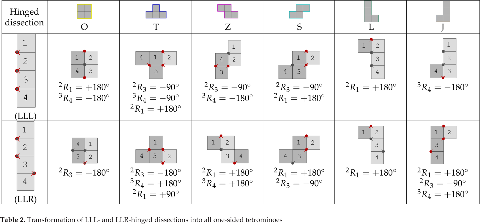
Proof. Four stacked identical squares can be dissected by three hinges in eight different ways, namely LLL, LLR, LRL, LRR, RLL, RLR, RRL, and RRR, where the sequence of L and R letters indicates the position of the hinges from up to down at a top view of the set of squares. Sequences RLR, RRL, and RRR are mirror reflections of sequences LLL, LLR, and LRL, respectively. Sequences LRR and RLL can be achieved by rotating sequences LLR and RRL by 180°, respectively. Therefore, up to congruence, four stacked identical squares can be dissected by three hinges in three different ways, namely LLL, LLR, and LRL. By Lemma 3, it is known that a LRL-hinged dissection of four identical squares cannot be rotated into all one-sided tetrominoes. Finally, Table 2 presents feasible sequences of transformations from the I-tetromino to all of the one-sided tetrominoes using the LLL- and LLR-hinged dissections. In such a table,
As far as the we know, the LLR-hinged dissection was presented for the first time in [35], where the authors showed that five identical squares cannot be hinged to be rotated into all pentominoes. Lemma 4 closes the circle for hinged dissections of tetrominoes. This result gives us the appropriate geometries for developing a self-reconfigurable robot module able to transform itself into any of the seven one-sided tetrominoes. We call this robot Hinged-Tetro. Any of the two types of hinged dissections (LLL and LLR) can be used for the intra-reconfiguration purposes, and for some inter-reconfigurability operations both geometries are needed.
Tetrominoes, popular for their use in the video game Tetris and common in tiling problems [38], have also been used as models for the better understanding of self-assembly processes in small molecules and nanoparticles [39]. In this section, we present a nested reconfigurable robot that is able to transform itself into any of the seven one-sided tetrominoes for the fundamental study of nested reconfigurable robotic systems.
Global design
The nested reconfigurable robotic system is a set of modular robots with individual reconfiguration characteristics that combine to form, for instance, a more complex robot mechanism suitable for performing specific tasks that are far from the capabilities of a single robot module. In this paper we focus on proof-of-concept with a 2D robot platform for the study of nested reconfiguration.
Based on the theory of hinged dissection of polyominoes in Section 2.2, we design a mobile self-reconfigurable robot called Hinged-Tetro that is able to transform itself into any of the one-sided tetrominoes. The geometry of Hinged-Tetro is highly useful for research in nested reconfiguration because the robot can easily rearrange its own blocks to change its structure (intra-reconfiguration) and also combine with other Hinged-Tetros to form, for instance, more complex morphologies to accomplish tasks that a single system could not tackle on its own (inter-reconfiguration).
The design of the proposed robot considers the simplicity in order to facilitate mass production in the future. Thus, the Hinged-Tetro's design is modular as it is an assembly with easily interchangeable shared components. This characteristic allows the Hinged-Tetro to be readily configured either as an LLL-hinged dissection or as an LLR-hinged dissection. Figure 9 presents a complete CAD of a fully-functional Hinged-Tetro in LLR configuration. Exploded views of the constituent blocks are presented. Block 2 is defined as being the system's anchor that never rotates during an intra-reconfiguration operation. This can be seen from Table 2 also. Accordingly, all heavier robot subsystems such as the drive system and electronics are concentrated in Block 2.

Design of a fully-functional Hinged-Tetro in LLR configuration. The modular design of the robot can be observed in the exploded views of the constituent blocks. Since Block 2 does not rotate during any intra-reconfiguration operation, the unit is used as the system's anchor and concentrates the heavier subsystems.
The Hinged-Tetro's body consists of four cubes connected by three revolute joints (Figure 9). The cubic shape of each block allows an easy intra-reconfiguration process while providing enough space to allocate appropriate sensors for inter-reconfiguration purposes. Each cube is hollow with internal ribbing to minimize weight while maintaining strength. The blocks have a modular design, allowing many parts to be reused in the system.
Other than the global structure, the mechanical design of Hinged-Tetro can be divided into three main parts: mobility unit, revolute joints, and docking system. Next, each of them is briefly discussed.
Transformation of LLL- and LLR-hinged dissections into all one-sided tetrominoes
Transformation of LLL- and LLR-hinged dissections into all one-sided tetrominoes
Because inter-reconfiguration processes require free movement in the Euclidean plane, the Hinged-Tetro must be designed with sufficient mobility regardless of its shapes. To accomplish this, Hinged-Tetro employs a holonomic drive system using four omni-wheels (active wheels) located on Block 2. During intra-reconfiguration, the wheels lock to avoid the movement of Block 2, while all the others rearrange their positions. Blocks 1, 3, and 4 rest on three metal ball casters (passive wheels) to facilitate movement during inter-reconfiguration locomotion and intra-reconfiguration operations.
Revolute joints
The reconfigurability of Hinged-Tetro is guaranteed by three revolute joints that connect the constituent blocks in a chain formation for performing the intra-reconfiguration operations. The single-axis rotation provided by each joint allows its adjacent blocks to rotate with a range of motion of up to 180°, as required by the lattice architecture resulting from the transformation operation between different tetromino shapes (see Table 2). Each joint is designed as a Butt/Mortise hinge. Block 2 works as a frame that the motor is docked to it for the rotations of Blocks 1 and 3. This last block works as a frame for the rotation of Block 4.
Docking system
The docking system is one of the essential parts of a reconfigurable robot. It has been proved that mechanical docking systems are stronger and more reliable than magnetic connectors [4, 40]. Thus, for both intra-reconfiguration and inter-reconfiguration operations, Hinged-Tetro utilizes a simple (one degree of freedom) but robust electromechanical mechanism based on gendered connectors. The male connector consists of three arms spaced 120° apart, similar to the blades of a mechanical fan. The centre shaft of this connector is directly attached to a positional servo motor and the ends of its blades are filleted to ease docking in conditions where systems are not well aligned. Figure 11 demonstrates the plain dimensions of the male and female connectors where there is a 3 mm tolerance designed between them. Once the two compatible faces mate, the male connector depresses a limit switch located behind the female connector to stop joint rotation. The connection finishes with a rotation of approximately 60° of the male connector, thus locking the two systems in place. The connection is kept secure as the positional servomotor holds the docking mechanism in the locked position as long as the robot is powered on. Details of the proposed docking system can be observed in Figure 9
Intra- and inter-reconfigurations in design
Figure 10(a) presents the design of Hinged-Tetro in its seven intra-reconfiguration shapes. An instance of inter-reconfiguration is depicted in Figure 10(b). This morphology is called the fork formation, which corresponds to the 16-omino presented in Figure 4(top-left). This formation can be made using four I-tetrominoes, two O-tetrominoes and two I-tetrominoes, or one L-tetromino, one J-tetromino, one I-tetromino, and one O-tetromino. In this last case, corresponding to the system shown in Figure 10(b), all Hinged-Tetro s but the module in the I-tetromino shape use the LLR-hinged dissection. LLL- and LLR-hinged dissections are needed in this combination to avoid the collision of some joints. The fork formation, useful for manipulation tasks, is an example of generating new morphologies in order to perform objectives that are far from the capabilities of a single unit.

Hinged-Tetro in its seven intra-reconfiguration shapes (a). An example of inter-reconfiguration, the fork formation for manipulation tasks (b). Such morphology can be made using three Hinged-Tetros in LLR configuration (L-, J-, and O-tetrominoes) and one Hinged-Tetro in LLL configuration (I-tetromino).

Plain view of the male and female connectors with tolerance indicated
In order to illustrate intra- and inter-reconfigurabilities, a prototype of Hinged-Tetro is built based on the CAD design in Section 3. Figure 12 shows the prototype, where every block is a cube with the dimension of 100 mm × 100 mm × 100 mm and the total weight of the Hinged-Tetro is 1.7 kg. Each wall of the cubes is 5 mm thick. In the prototyping, the shells, male connectors, brackets of joint servo are fabricated using 3D printers with ABS and PL A plastic materials and minimal lathe operations. The remaining components, such as the joint motors and docking servos, are selected commercial off-the-shelf.

Prototype of Hinged-Tetro for testing the basic operations of intra-reconfiguration
The electronic system of Hinged-Tetro can be divided into four units: the main control unit, the reconfiguration unit, the mobility unit, and the docking unit, as shown in Figure 13. The realization of the main control system located in Block 2 starts from a control an Arduino Mega 2560 microcontroller board with 256 KB of flash memory running at 16 MHz. Communication with the host PC is established via UART TTL serial communication through a USB tether that also provides power for the control board. The intra-reconfiguration is realized by the reconfiguration unit, which consists of three re volute joints. Each revolute joint of Hinged-Tetro is powered by a continuous rotation servo (Herkulex Dongbu motor) with a stall torque of 24 kgf cm. To change to any configuration, the corresponding motor rotations to the predefined angles are realized by controlling the rotation of every joint motor. The mobility is realized by four omni-wheels (OW003, Robot-R-Us) driven by two Sabertooth 2×25 motor drivers located in Block 2. Regarding the docking system, the centre shaft of each male connector is attached to a micro servo (HD-1800A) with a stall torque of 1.3 kg-cm. The whole system is supplied with 7.4V as VDD.
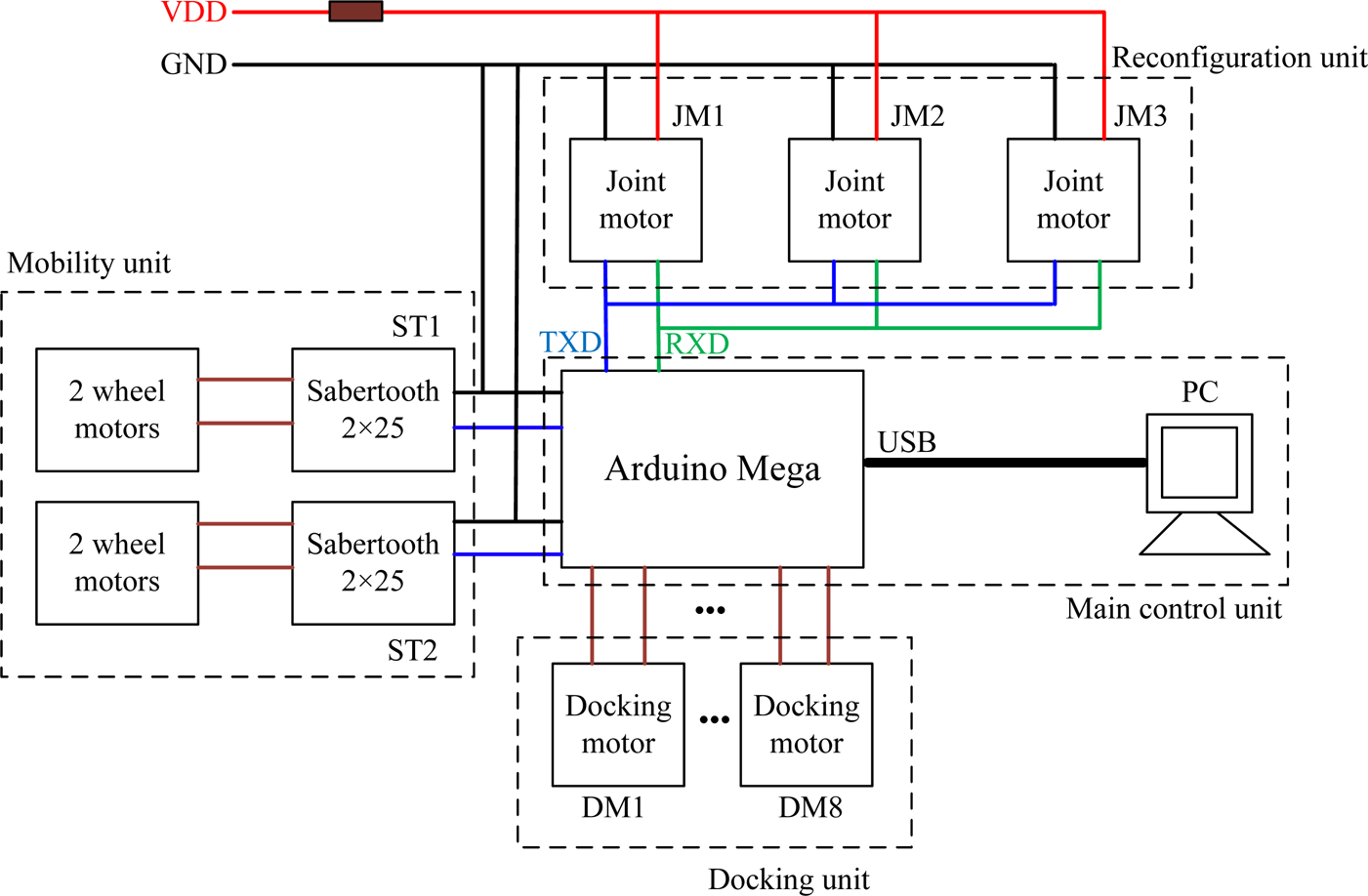
Scheme diagram of Hinged-Tetro's electronic system
For performing intra-reconfiguration operations, the presented prototype of Hinged-Tetro utilizes a finite-state machine of seven states, one for each of the one-sided tetrominoes. An example of the required movements for the transition between states can be observed in Table 2. In the tests, Hinged-Tetro receives triggering commands from an operator on a computer, then proceeds with the required transition. All transformations are programmed to prevent crashes between blocks regardless of the current state of Hinged-Tetro. The snapshots of intra-reconfiguration showing the transformation of the prototype into all its intra-reconfiguration shapes following the sequence I → O → T → Z → S → L → J → I are given in Figure 14.

Intra-reconfiguration of the Hinged-Tetro following the sequence: I → O → T → Z → S → L → J → I
To test the energy consumption of the joint motors for every reconfiguration, we supply a 7.4V power source only to the joint motors, which means the docking motors and wheels driven system are not connected to the source. The current consumed by the joint motors when operating reconfiguration is measured. To do so, a 1 Ω resistor is placed between the positive end of the power supply and the positive end of the joint motors so that the voltage drop across the resistor is equal in magnitude to the current demanded by the reconfiguration. The current is characterized by noisy peaks that are smoothed out by the use of a moving average. Figure 15 shows the current demands of transformation from S to T and from T to S. The power required by the motors to maintain a shape is approximately 1.48W (7.4V × 0.2A). Additional power of about 1.96W (7.4V × o.4A) to 3.7W (7.4V × 0.5A) is needed to perform the reconfiguration.

Current measurements during the reconfigurations of S → T and T → S
Table 3 gives all the experimental data of time and current consumption for reconfiguration from any one shape to the others. In 42 experiments, all of them succeed in reconfiguration. From the table, it is found that reconfigurations from any shape to Shape T require the longest time, i.e., 2.67 seconds on average. Furthermore, Shape T takes the longest time (i.e., 2.25 s) to change to other shapes. Moreover, the corresponding current consumptions are high in reconfigurations involving Shape T because it demands the most joint rotations. In contrast, shape L consumes the shortest time and smallest current. The reconfigurations from other shapes to L are 1.25 seconds and 0.44 A in average, and those from L to other shapes spend 1.42 seconds and 0.41 A. The reason opposite to T is that the reconfigurations involving L demand the fewest joint rotations. Therefore, Shape L is the priority choice for the task executions, and conversely Shape T should be avoided from the energy point of view. This will be investigated in the planning strategy of reconfiguration in future research.
Inter-reconfiguration is shown using two Hinged-Tetro robots with the same design. An inter-reconfiguration scenario using two I-shaped Hinged-Tetro s is presented in Figure 16(a). The lower Hinged-Tetro moves leftwards and is brought to a standstill at the sixth section. Then, the robot moves vertically with respect to the original motion direction to attach and dock with the upper robot at the ninth second. Another scenario is shown in Figure 16(b) where the I-shaped Hinged-Tetro moves straightly and docks to the T-shaped one in four seconds. The snapshots validate the inter-reconfigurability of the proposed self-reconfigurable module.
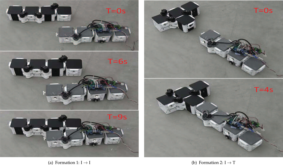
Snapshots of inter-reconfiguration of Hinged-Tetro
The nested reconfigurable robots have a wide range of application prospects. As far as we know, the existing cleaning robots cannot adapt their configurations to the environments. The 2D prototype presented in this paper could be improved to be a new generation of floor cleaning system. On one hand, thanks to its intra-reconfigurability, the individual robot could reconfigure into the shape that fits the structure and size of the space so as to access the area where a conventional cleaning robot, such as a Roomba, cannot reach. On the other hand, thanks to the inter-reconfigurability, multiple robots can combine into a robotic formation that could be efficient for cleaning tasks in large areas. Moreover, given the popularity of the video game Tetris and its pieces, Hinged-Tetro is suitable for games, education, lighting, and outreach purposes.
Time and current consumption required from one configuration to the others

The idea of nested reconfiguration has been introduced and discussed. In contrast to the conventional classification method, we propose classifying modular and reconfigurable robots into intra-, inter-, and nested reconfiguration types.
In this paper, a mobile self-reconfigurable robot module, called Hinged-Tetro, conceived for the study of nested reconfiguration, has been presented. Hinged-Tetro was based on the theory of hinged dissection of polyominoes, particularly on the LLL- and LLR-hinged dissections of four identical squares. It was shown that such geometries are the unique maximum natural hinged dissections, up to congruence, that can be rotated into all one-sided tetrominoes, the Tetris pieces. An initial design of Hinged-Tetro was properly discussed and transferred into a prototype. The experiments of intra- and inter-reconfiguration were performed and verified to be successful, which proved the nested reconfigurability of the proposed module. Based on this, some further analysis experiments checking current/energy and time consumptions were reported, from which we know that the Shape T was the most energy and time-consuming configuration, and Shape L was the other way round.
The resulting two-level reconfiguration process in the proposed concept implied several technical challenges in hardware design, planning algorithms, and control strategies. Some of the ongoing efforts of our group included the design of a better docking mechanism, the autonomous inter-reconfiguration between two or more modules, design of a 3D Hinged-Tetro, and the development of algorithms for programmable assembly using Hinged-Tetros, etc.
Footnotes
7.
This work was fully supported by the SUTD-MIT International Design Centre, Singapore under grants IDG31200110 andIDD41200105.