
Abstract
Self-reconfigurable robot is a complex system composed of multiple modular robots. Aiming at high efficiency and low energy consumption of self-reconfigurable robot configuration transformation, a self-reconfiguration strategy based on module mapping of the common parts is proposed. This strategy describes the configuration of the robot in the form of a graph, and a method to determine the central node of configuration is proposed. The central node module as the starting node for comparison of different configurations, and the common part between the two configurations is reserved. Then the module closest to the target module is searched, the target configuration is reconfigured from the inside to the outside with the minimum energy consumption constraint. Finally, based on the experiment results, compared with other self-reconfiguration strategies, the proposed self-reconfiguration strategy reduces the times of reconfiguration operations and improves the reconfiguration efficiency.
Introduction
The modular self-reconfigurable robot 1,2 is composed of several modules with connectors. When faced with an unstructured dynamic unknown environment, it can reconfigure different configurations through a series of operations such as moving, disconnecting, and connecting, so as to adapt to different environments and perform different tasks. Modular self-reconfigurable robots are mainly divided into three categories according to their topological structure 3 –5 : (1) lattice type: Most of the modules are cubes. In the configuration, each module is on the regular grid. Changing the position of the module, the configuration changes accordingly, such as Melecubes, 6 Roombots, 7 –9 M-Cube, 10,11 Cebot, 12,13 and so on. (2) Chain type: The modules are connected in series to form a chain type, such as CONRO, 14,15 Xmobot, 16 USS, 17 PolyBot, 18,19 and so on. (3) Hybrid type: This module not only has good mobility capability but also has the structure characteristics of lattice and chain, such as M-TRAN, 20 –22 SuperBot, 23 –25 SamBot, 26,27 SMORES, 28 and so on.
Aiming at the transformation between different configurations of self-reconfigurable robot, Casal and Yim 29 proposed the strategy of self-reconfiguration of Divide-and-Conquer to match configurations in a layered manner, which involves many redundant reconfiguration steps and leads to low reconfiguration efficiency. Butler et al. 30 proposed a Melt-Group self-reconfiguration algorithm based on Crystalline module. This algorithm uses centralized control, which gradually “grows” the target configuration from a simple configuration. The centralized control method will reduce the efficiency of self-reconfiguration as the number of modules increases. Stoy et al. 31 designed a method to transform configuration based on the transfer of hormone signals between modules to stimulate other hormones and generate corresponding reconfiguration action. This method has a single applicability, and the signal strength will be weakened in the transmission process, affecting the reconfiguration operation. Chao Liu 32,33 proposed a self-reconfiguration strategy based on configuration decomposition for SMORES modules. By mapping two configurations with the same number of modules, a distributed reconfiguration operation was developed. This method did not specify the mapping starting point and did not take energy consumption into account, which made the reconfiguration efficiency low. The above self-reconfiguration strategies are all only suit for two configurations with the same total number of modules, but two configurations with different total number of modules have not been studied.
To improve the efficiency of self-reconfiguration for modular spherical robot, this article proposes a self-reconfiguration strategy based on module mapping of the common parts, which can reduce the energy consumption of configuration transformation by retaining common parts between the two configurations, shorten the moving distance of modules during the reconfiguration process and improve the efficiency of self-reconfiguration.
The structure of the article is as follows: The second section introduces the hardware structure of the spherical module; the third section introduces the configuration representation method of the self-reconfigurable robot based on the spherical module; the fourth section proposes the self-reconfiguration strategy, including determination of the central node module of the configuration, module mapping of common parts, and reconfiguration operation planning; the fifth section gives some experiments and results; and in the sixth section, the conclusions and future work are given.
Spherical module
The self-reconfigurable robot system studied in this article takes the connectable and openable spherical robot as the basic module, which is a hybrid-type modular robot. It combines the design concept of spherical robot and modular robot to solve the problem of poor motion ability of traditional modular robot. As shown in Figure 1, it is an evolutionary version of the robot designed in Ma et al., 34 there are six retractable and rotatable connectors distributed on the spherical module. Three of them are active connectors (connector 1, 3, 5) and other three connectors are passive connectors (connector 2, 4, 6), and connector 1 and connector 2 can swing up and down. The connection between connectors mainly depends on mechanism (latch structure), while electromagnetic devices are installed to assist the connection and ensure the reliability of the connection between the two modules. Considering the communication requirement between modules, there are some communication interfaces on the connectors of the module.

The structure of spherical module. (a) The structure of spherical module with spherical shell. (b) The structure of spherical module without spherical shell.
The spherical module can not only perform tasks by rolling alone but also connect with other modules to form different configurations. The spherical module moves in two ways: (1) Spherical shell closure: the movement of the spherical module is realized by deviation of mass center, and the movement of the mass block inside the module can change the mass center of the spherical module. When the mass block is driven forward by the long axis motor, the spherical module starts to move forward. When the short axis motor drives the mass block to the left and right, the spherical module turns to the corresponding direction, as shown in Figure 2(a). (2) Spherical shell opening: The spherical module becomes a wheel-type robot, and the left and right hemispherical shells are equivalent to the left and right wheels of the wheel-type robot, which can realize differential motion and are mainly used for the connecting motion between modules, as shown in Figure 2(b).

The two motion modes of spherical module. (a) Spherical shell closure. (b) Spherical shell open.
All connection modes between unit modules are listed in Figure 3. Connection modes (a) to (h) can be butted through the proximity of two spherical unit modules and the expansion and contraction of connectors. However, due to the limitation of the unit module itself and the extension length of the connector, the connection mode of (i) will cause interference when the two spherical unit module connectors 5 and 6 are connected. Therefore, there are only eight connection modes (a) to (i) in the figure between spherical unit modules. And among the eight connection modes, (e) requires two spherical unit modules to be close to each other, so as to provide a horizontal coupling force for the connection between them to complete the docking smoothly, while all other connection modes can be moved from one spherical unit module to the vicinity of another spherical unit module, and their connectors can be aligned to complete the connection.

All connection modes between unit module. (a) Connector 1 and connector 2 are connected. (b) Connector 1 and connector 4 are connected. (c) Connector 1 and connector 6 are connected. (d) Connector 3 and connector 2 are connected. (e) Connector 3 and connector 4 are connected. (f) Connector 3 and connector 6 are connected. (g) Connector 5 and connector 2 are connected. (h) Connector 5 and connector 4 are connected. (i) Connector 5 and connector 6 are connected.
In the connection relationship (a) to (h) in Figure 3, not every connected spherical unit module can move flexibly. Among the four connection relationships, such as (b), (d), (f), and (h), due to the rigid connection between the two modules and the limitation of the weight of the spherical unit module, the two modules cannot move flexibly under these four connection modes. Under the three connection relationships, such as (a), (c), and (g), the long axis motor of one spherical unit module can be powered off, and the connected other spherical unit module can drive it to move, just like a four-wheel vehicle. In this way, such as (e), the two hemispherical shells close to the two connected unit modules follow, and the other two hemispherical shells are equivalent to the two wheels of a two-wheeled vehicle. The module in this connection mode can still move flexibly and stably like a two-wheeled vehicle.
Configuration representation
The configuration representation of self-reconfigurable robot is the basis of the self-reconfiguration strategies. Combining the characteristics of the spherical module with the knowledge of graphics, the spherical module can be simplified to a node, as shown in Figure 4. Mi denotes the number of the module in the self-reconfigurable robot system, and connection line denotes the connectors distributed on the spherical module. The digital 1 to 6 corresponds to the number of the connector, where the odd numbers indicate the active connector and the even numbers indicate the passive connector. Only the connection between the active connector and the passive connector is an effective connection.

The graphic representation of module.
The self-reconfigurable robot is composed of several modules and can be described by the directed topology diagram in the graph theory. Let

The configuration representation of snake configuration. (a) The graphical representation of the snake configuration. (b) The topology representation of the snake configuration.

The configuration representation of planar quadruped configuration. (a) The graphical representation of the planar quadruped configuration. (b) The topology representation of the planar quadruped configuration.
Given two configurations

The common part of two different configurations G
1 and
Commonly used nomenclature is listed in the following.
Gi
: Initial configuration;
Ti
: Target configuration;
Mc
: The central node of the initial configuration;
Self-reconfiguration strategy
The self-reconfiguration strategy is defined as: based on the given two different configurationsG and T, a strategy is formulated to reduce the transformation steps from configuration G to configuration T and decrease energy consumption. The self-reconfiguration operation of most robots consists of disconnecting, moving, and connecting. Connection operation requires two modules to align and then activate the relevant connecting mechanism. Correspondingly, a disconnection operation invalidates the connection of the connector involved and separates the two modules. This article not only decreases the energy consumption of connection and disconnection but also considers minimizing the energy consumption in the moving process.
The self-reconfiguration strategy can be divided into three steps: First, the central node module of the configuration is determined. Then, the central node module is used as the starting node of configuration comparison to obtain the common parts of the two configurations. Finally, the common parts move to the corresponding position by differential motion according to the target configuration information and the noncommon parts are reconfigured.
Central node module
In any configuration of self-reconfigurable robot, the array
In any configuration of a self-reconfigurable robot, all modules remain connected, and each module communicates with the connected modules obtaining its own

where j is the module, i is the connector connected with other modules, n is all connector of the Mj .
The
Search central node module.


Table 1 shows the
The
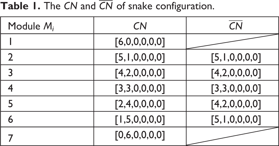
The

Module mapping of common parts
The self-reconfiguration process of modular robot is that the robot transforms from the initial configuration to the target configuration according to the characteristics of the environment. In this process, the initial configuration and the target configuration should be analyzed and compared to find out the common parts and noncommon parts between the two configurations. The existing connection between modules in the initial configuration should be retained as much as possible in the target configuration so as to reduce the energy and time consumption of disconnection and connection operation, and improve the reconfiguration efficiency.
The energy consumption of each self-reconfiguration operation from G to T can be defined as:
Then the total energy consumed by the robot from G to T is as follows:

In order to improve the efficiency of reconfiguration and reduce the energy consumption in the process of self-reconfiguration, firstly, the initial configuration and the target configuration are compared to obtain all the common parts of the two configurations, and the connection of the common parts is retained to reduce the times of disconnection and connection operations in the self-reconfiguration process, and ensure that
Based on the given initial configuration
Note that there are several conflicts in the reconfiguration need to consider: The Mc
of initial configuration is not the Multiple edges of the initial configuration have the same connection information with one edge of the target configuration. One edge of the initial configuration has the same connection information with multiple edges of the target configuration. The adjacent edges in the initial configuration have the same connection information with the nonadjacent edges in the target configuration. The adjacent edges in the target configuration have the same connection information with the nonadjacent edges in the initial configuration.
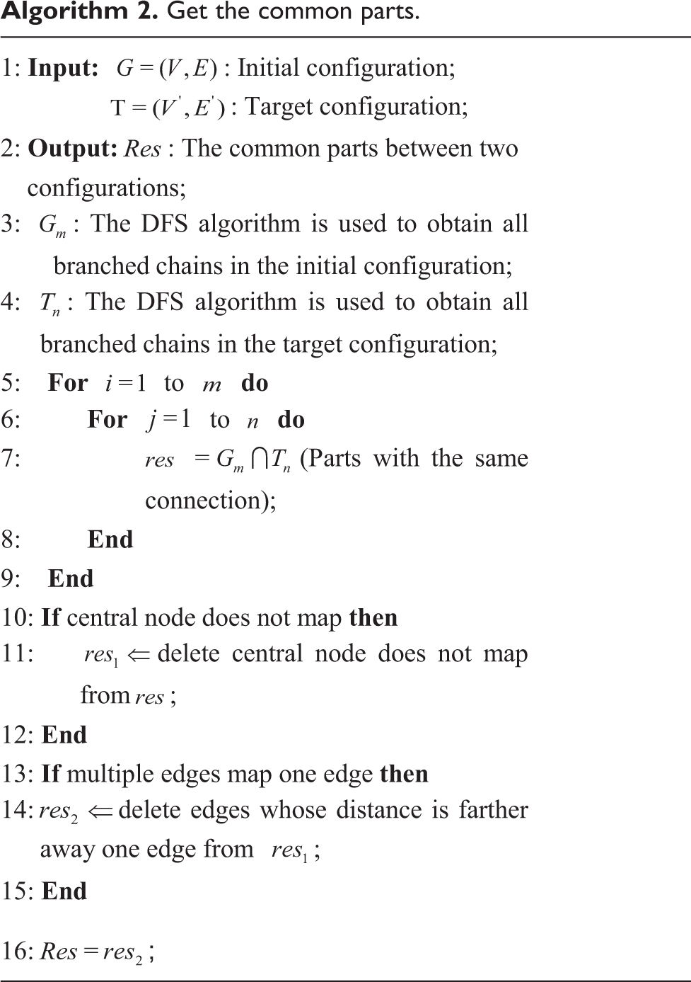
Therefore, all results should be filtered. For (1), the central node of the initial configuration that does not map to the central node of the target configuration is deleted from all results. For (2) and (3), the coordinates of the central node of the initial configuration are assigned to the central node of the target configuration. In the case of multiple edges have the same connection information with one edge, the distance between each edge and this edge is calculated respectively, and the edge with the shortest distance is selected to map with this edge (if there are several shortest edges, choose one of them), and the others are deleted from the result. For (4) and (5), the distance between the two mapping edges is also calculated, and the pair of mapping edges with the shortest distance is retained. (If more than one edge meets the condition, select any one.) In this way, the remaining mapping edges are all the common parts of configuration G and configuration T. The algorithm pseudo code of this process is as seen in Algorithm 2.
Get the common parts.

Reconfiguration operating
The process of transforming self-reconfigurable robot from initial configuration G to target configuration T follows the principle of disconnecting first and then connecting. First, disconnect the connection of noncommon parts in initial configuration G. Then, according to the connection information of target configuration T, the module performs the reconfiguration from the inside to the outside. This can avoid locking due to the occupancy conflict of the module during the reconfiguration process and make other modules unable to connect with the module.
After mapping the initial configuration G with the target configuration T, the noncommon part of the initial configuration G is separated according to the minimum times of disconnections. The common part of initial configuration G which is the same as target configuration T moves to the corresponding position of target configuration T through differential motion, as shown in Figure 8(b). Next, the reconfiguration operation is conducted for the noncommon parts. According to the connection information of target configuration T, the central node module of initial configuration G or the common part containing the central node module is taken as the reconfiguration center, and the number of the target module in the current configuration is determined, as shown in Figure 8(c). Then, the target modules broadcast their location information one by one in order, all the surrounding modules calculate the distance from the modules to their own the target position, and select several modules closest to the target modules in the current configuration (satisfying the number of connections required by the target modules), as shown in Figure 8(d). Each module uses the planning algorithm (such as RRT, etc.) to generate the feasible path to the target module according to the environmental information and its own state, and conduct the orientation transformation to connect with the target module. In this way, the position of the target module in the current configuration is broadcast, and the nearest module is determined. Feasible path is generated to ensure the safe and orderly movement of the module near the module to be connected to complete the connection operation, and finally implement the target configuration T, as shown in Figure 8(e), (f), and (g). The reconfiguration process from snake configuration to planar quadruped configuration is shown in Figure 8.

Reconfiguration process from snake configuration to planar quadruped configuration. (a) The common parts between the G and T. (b) Move common parts. (c) The target modules of the first layer. (d) Modules close to the target modules of the first layer. (e) Connect to the target module and the target modules of the second layer. (f) Connect to the target module and the target modules of the third layer. (g) The target configuration.
The self-reconfiguration strategy takes into account the energy consumption during the transition from initial configuration to target configuration. By comparing the connection information of initial configuration and target configuration, the common parts of them are retained, thus reducing the energy consumption caused by disconnection
Experiments and results
We have implement the algorithm on a desktop PC (Intel Core i5-6500, 3.20 GHz, 4 GB SDRAM). We perform two types of experiments. First, we reconfigure two configurations with different total number of modules to verify the feasibility of the algorithm. Second, we reconfigure two configurations with same total number of modules to verify the superiority of the algorithm compared with other algorithms.
The total number of modules is different
In the existing self-reconfiguration strategies, such as Hou et al., 35 most self-reconfiguration strategies are to find the part with the most same connection relationship between the initial configuration and the target configuration, keep it unchanged in the initial configuration, then reconfigure other parts, and they are only applicable to the case that the total number of modules in the initial configuration and the target configuration are the same. This article is looking for the part with the most same connection relationship between the initial configuration and the target configuration and considers reducing the energy consumption in the transformation process. Therefore, the self-reconfiguration strategy proposed in this article considers the energy loss on its basis, so it has certain advantages.
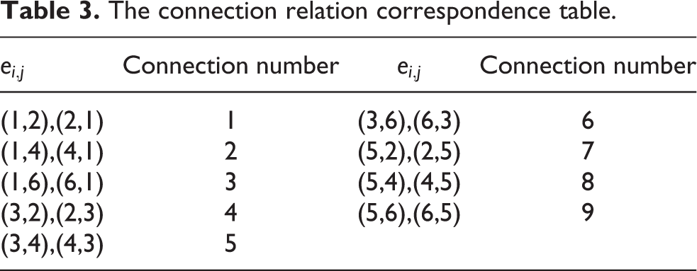
In this section, we completed two reconfiguration tasks to verify the feasibility of the self-reconfiguration strategy. First, we completed the reconfiguration task from snake configuration to planar quadruped configuration. (The total number of modules in the target configuration is larger than that in the initial configuration.) The common parts of snake configuration and planar quadruped configuration are shown in Figure 9 and represented by dotted lines. The combination of digit and dot is used to represent the module and connection line represents the connection between two modules, the digit on the connection line corresponds to the connection relationship between the two modules as shown in Table 3. For example, in the snake configuration of Figure 9, the digital 1 on the connection line between
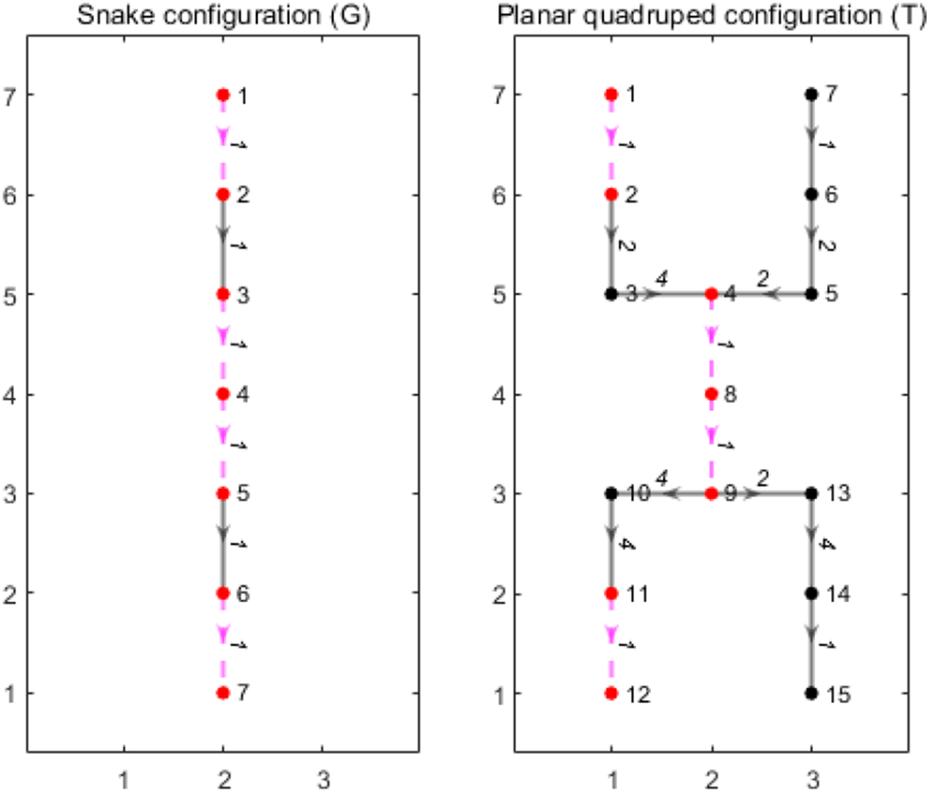
The common parts of snake configuration and planar quadruped configuration.
The connection relation correspondence table.
The all common parts of snake configuration and planar quadruped configuration.

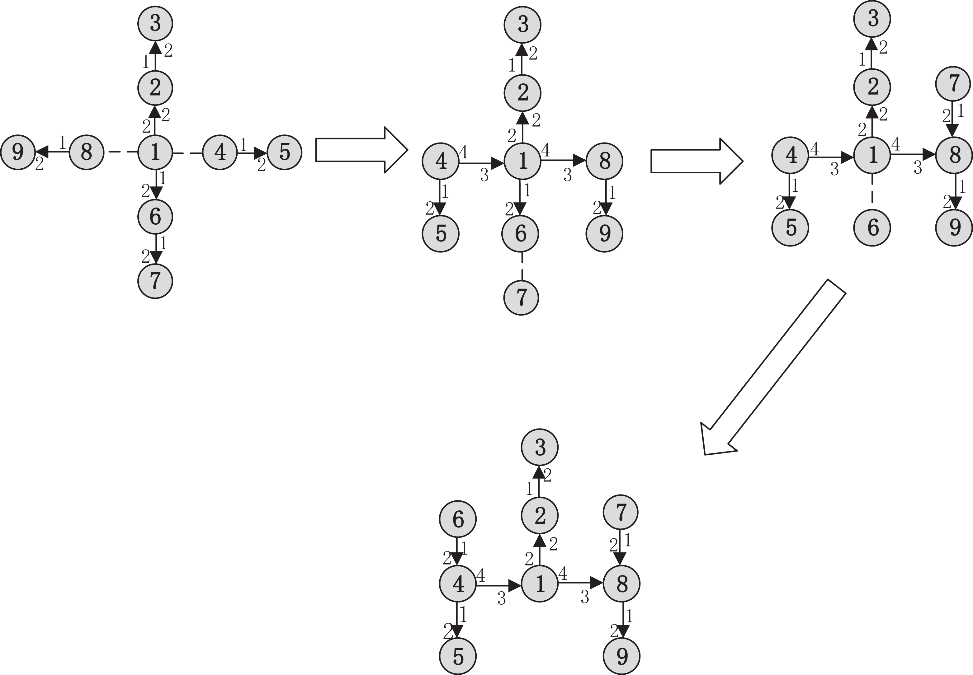
Second, we completed the reconfiguration task from windmill configuration to H-shape configuration. (The total number of modules in the initial configuration is larger than that in the target configuration.) The common parts of snake configuration and planar quadruped configuration are shown in Figure 10 and represented by dotted lines. The central node of windmill configuration is
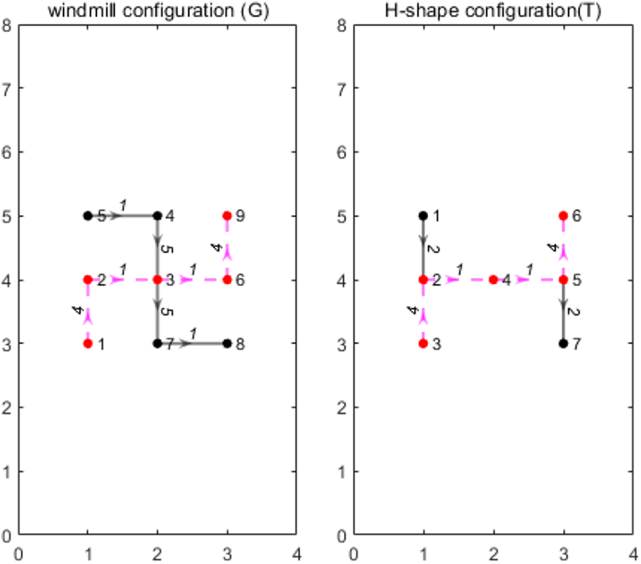
The common parts of windmill configuration and H-shape configuration.

Reconfiguration process from windmill configuration to H-shape configuration. (a) The common parts between the G and T. (b) The reconfiguration center. (c) The target modules and modules close to the target module. (d) Connect to the target module and form target configuration.
The total number of modules is same
In this section, we completed two reconfiguration tasks and compared them with other reconfiguration strategies to verify the superiority of the strategy. First, we completed the reconfiguration task from H-shaped configuration to snake configuration. The common parts of H-shaped configuration and snake configuration are shown in Figure 12 and represented by dotted lines. The center node of H-shaped configuration is

The common parts of H-shape configuration and snake configuration.

Reconfiguration process from H-shape configuration to snake configuration by this article’s strategy.

Reconfiguration process from H-shape configuration to snake configuration by Chao Liu’s strategy.
In Dutta et al., 36 the energy consumption of self-reconfigurable robot in configuration transformation is defined, but there is no quantitative analysis. In order to facilitate comparison with other self-reconfiguration strategies, this article uses the method of defining its energy consumption for reference, and makes quantitative assumptions on its energy consumption, as follows:
Since the movement of the unit module requires continuous power supply to the motor, therefore the energy consumption is much higher than that of connection. In addition, the connection process needs to align the connector first, which is higher than the energy consumption of disconnecting two modules. Therefore, it is assumed that:


where
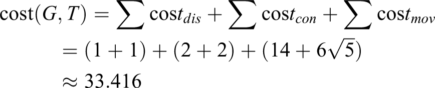
By comparing the two self-reconfiguration strategies, the energy consumption of the robot guided by the self-reconfiguration strategy proposed in this article is obtained as follows:
The energy consumption of the robot guided by Chao Liu’s self-reconfiguration strategy is as follows:
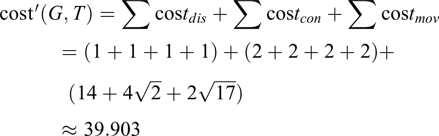
In conclusion,
Second, we completed the reconfiguration task from A configuration to B configuration. The common parts of A configuration and B configuration are shown in Figure 15 and represented by dotted lines. The center node of A configuration is M
1, and that of B configuration also is M
1. The result of module mapping of the common parts are

The common parts of A configuration and B configuration.

Reconfiguration process from A configuration to B configuration by this article’s strategy.
Reconfiguration process from A configuration to B configuration by Chao Liu’s strategy.
The energy consumption of the robot guided by the self-reconfiguration strategy proposed in this article is obtained as follows:

The energy consumption of the robot guided by Chao Liu’s self-reconfiguration strategy is as follows:

In conclusion,
Conclusion
In this article, self-reconfiguration strategy based on module mapping of the common parts is proposed. The goal of this strategy is to minimize the energy consumption in the process of configuration transformation. The connection information between the initial configuration and the target configuration is fully compared to determine the common part between the two configurations. The existing connection between the modules in the initial configuration is retained in the target configuration as far as possible, so as to ensure minimum energy consumption for connection and disconnection during conversion process. Also in the process of reconfiguration, the module closest to the target module is used for connecting operation, which reduces the energy consumption in the process of moving, thus minimizing the energy consumption of the whole system and improving the efficiency of self-reconfiguration. Through the experiment of self-reconfiguration strategy, the results show that the self-reconfiguration strategy is effective and feasible, and the strategy is not only suitable for two configurations with the same number of modules but also suitable for two configurations with different number of modules. Future work will focus on physical experiments.
Footnotes
Declaration of conflicting interests
The author(s) declared no potential conflicts of interest with respect to the research, authorship, and/or publication of this article.
Funding
The author(s) disclosed the receipt of the following financial support for the research, authorship, and/or publication of this article: This work was supported in part by the Fundamental Research Funds for Central Universities under Grant 2019XD-A16.
Supplemental material
Supplemental material for this article is available online.
References
Supplementary Material
Please find the following supplemental material available below.
For Open Access articles published under a Creative Commons License, all supplemental material carries the same license as the article it is associated with.
For non-Open Access articles published, all supplemental material carries a non-exclusive license, and permission requests for re-use of supplemental material or any part of supplemental material shall be sent directly to the copyright owner as specified in the copyright notice associated with the article.