
Abstract
This paper presents the design and implementation of a new modular self-reconfigurable robot. The single module has three joints and can perform rectilinear motion, lateral shift, lateral rolling, and rotation. A flexible pin-hole-based docking mechanism is designed for self-assembly. With the proposed infrared-sensor-based docking method, multiple modules can be self-assembled to form versatile configurations. The modules communicate with each other through ZigBee protocols. The locomotion planning and geometry analysis of the single module are presented in detail and the efficiency of the single module's mobility is also demonstrated by experimental results. In automatic docking experiments with two modules, the proposed method is shown to be able to achieve an average success rate of 78% within the effective region. The average time of the docking process is reduced to 75 s. The maximum velocity of the I-shaped robot is up to 3.6 cm/s and the maximum velocity of the X-shaped robot is 4.8 cm/s. The detach-dock method for I-to-X transformation planning is also verified. The ZigBee-based communication system can achieve 100% receiving rate at 55 ms transformation interval.
1. Introduction
Modular self-reconfigurable robots have become an important research topic in recent years [1]. A modular self-reconfigurable robot system is composed of a group of homogeneous or heterogeneous simple modules. The capabilities of single modules are limited, but robots assembled with multiple modules exhibit great versatility and robustness. Such assembled robots can adapt to various tasks and environments [2].
The goal of this work is to create a robot system for deploying wireless emergency networks for searching and rescuing in harsh environments [3]. Modular robot systems with great locomotion capabilities can do this work better than other robots. Modular robots have a wide variety of mechanical structures and locomotion patterns. They are commonly divided into three categories based on the geometric arrangement of their units, i.e., chain architecture, lattice architecture, and hybrid architecture [4]. So far, a great variety of modular self-reconfigurable robot systems have been designed. Polybot [5], CkBot [6], GZ-I [7], etc., are typical chain-type modular robots with only one degree of freedom (DOF). The lattice-type modular robots commonly have more docking interfaces, such as Molecubes [8]. The chain-type and lattice-type modules cannot move independently. Several new chain-type modular robot systems have been developed in recent years, e.g., Sambot [9] and SMORES [10]. In order to allow the module to move flexibly, the two systems add wheels into the mechanical design of the module. CONRO [11], SUPERBOT [12], MTRAN III [13], iMobot [14], and ModRED [15] belong to the hybrid architecture type. Compared with the other two systems, the single modules of hybrid systems have more flexible locomotion capabilities. The more DOFs the module has, the more flexible the locomotion the module performs. However, the mechanical design and motion control of these hybrid systems are complex. A self-reconfigurable module for deploying should be designed with simple structure and flexible locomotion. The proposed module here is based on the chain-type architecture. The single module with three DOFs, however, can move flexibly and independently.
The simple structure is not the only design indicator. No matter what locomotion the single module performs, it cannot deal with rough environments. However, various large configurations assembled by modules can handle such environments well. Self-assembly and transformation are another two remarkable features, of which the docking operation is the final step. The automatic docking mechanism includes electromagnetic connectors [16–17] and mechanical connectors [18]. The connecting strength and the docking precision must be considered. The electromagnetic docking connectors are simple and can be easily implemented, but cannot provide sufficient connecting strength. Shen et al. [19] proposed a genderless connector for the SUPERBOT system. The MTRAN modules were equipped with hook-mechanism-based male/female connectors [20]. However, these mechanisms need high docking accuracy. Therefore, a new heterogeneous pin-hole-based connector able to provide enough connecting strength and tolerate large misalignment errors was designed.
Self-assembling operations must be guided by some extra sensors. However, transformation planning can be implemented through many methods, e.g., inverse kinematics. The last docking step also needs sensors to adjust relative position deviations of connectors. At the present time, there are two types of guiding method, i.e., the infrared sensor method [21] and the visual sensor method [22]. The advantages of the visual sensor method are that it can guide the docking process in a large region. But the hardware requirements are high. The infrared sensor guiding method for the modular robot has low hardware requirements and the operation is simple. We also propose here a detach-dock approach for the I-to-X transformation.
Existing communication systems of modular self-reconfigurable robot systems include CAN-BUS [23], infrared communication [24], and Bluetooth [25]. CAN-BUS-based systems can provide high transmission speed, designing the connectors is complicated. The wired method also requires precise alignment. The infrared communication systems are unreliable in outdoor environments but have crosstalk problems. Radio frequency communication is adopted in modular self-reconfigurable robot systems to overcome these. However, Bluetooth communication systems cannot provide enough network capacity to meet the scale requirements of modular self-reconfigurable robots. Due to the goal of this work, the wireless sensor network is more suitable for the modular robot systems here. Each sensor thus supplements the others without adding extra communication systems.
In this paper, the design and implementation of the proposed robot module is presented. The robot design and implementation is introduced in Section 2. The docking method, locomotion planning and geometry analysis of the single module are presented in Section 3. The mobility test results of the single module and two assembled modules, the performance of the proposed docking method, the I-to-X transformation, and the data transmission of the wireless communication system are given in Section 4. Section 5 will present a conclusion and introduce future work.
2. Robot design and implementation
2.1 Mechanical design
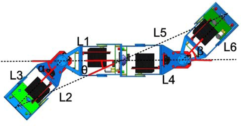
As shown in Figure 1, a single module of the proposed modular robot has one yaw joint and two pitch joints. In this paper, the joint with a female connector is called the tail joint, and the joint with a male connector is called the head joint. Each joint can rotate ±90° to provide the necessary flexibility for the module to perform locomotion without any external assistance. The single module deployed in rough environments may roll over. The unsymmetrical structure presented in [26] cannot move when the module is upside-down. So, the ideal structure of the module must be symmetrical. The body shell is one of the key parts for implementing a modular self-reconfigurable robot; this is a set of aluminium frames which support the main body of the module. The size of the module is 264 mm×71.5 mm×65 mm. The proposed modules can be assembled into I-shaped and X-shaped configurations, etc.
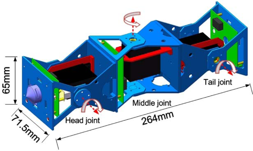
The mechanical structure of the proposed robot module
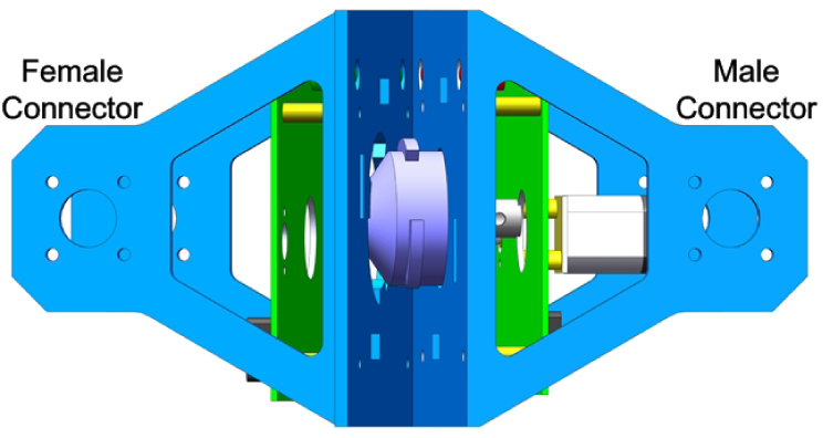
In [5], [13], and [27], the authors proposed pin-hole-based connectors. The male connectors with more than two pins increase the docking accuracy requirements. Inspired by [28], a new heterogeneous docking mechanism with one guide pin is designed. The mechanical structure is shown in Figure 2. The guide pin is driven by a motor and has a 60° conical surface and three fan-shaped locking plates. The conical surface can tolerate misalignment errors of ±15° and ±3 cm in the docking procedures. The female connector only has a docking hole in the surface with no mechanical or electrical parts. In the self-assembling procedures of two modules, the guide pin is plugged into the docking hole and rotated 60° to lock the female connector. The contours of the docking hole match with the fan-shaped locking plates. If the two assembled modules want to separate from each other, the guide pin only needs to rotate 60° for the unplugging process.
Structure of the docking mechanism
The fan-shaped locking plates and the contours bear the stress in the movements. They need to provide sufficient mechanical strength to keep reliable connection. Stress and deflection of the locking plates and contours are analysed by the Simulationxpress software. The analysis results are illustrated in Figure 3. The external force is set at 133 N, which is the weight of 20 modules. The results verify that the docking mechanism is safe for movement or transformation of the large assembled configurations.

Stress analysis results of the docking mechanism. The thickness of both connectors is 2 mm. The external force is 133 N. The maximum deflection is about 1.55 mm.
2.2 Hardware design
Each module has three identical mainboards, which control the joint motors and wireless networking. Figure 4 presents the architecture of the mainboard. The processor is a ZigBee compliant wireless microcontroller with an on-chip 32-bit RISC core and a 2.4 GHz transceiver. In case the working motor interferes with the neighbouring circuits, the joint motors and the digital circuit are powered by two sets of batteries respectively.

Hardware components of the proposed modular self-reconfigurable robot
When large configurations are moving, some abnormal operations will cause the joint motors to lock. This will damage the motors and the control board if no precaution is taken. A current sensor is used to monitor the real-time working current of the motors. If the working current of the joint motor is detected to exceed a normal threshold, the system will shut down the power supply to the joint motors. Some sensors can be added into the system through the SPI interface.
3. Docking and locomotion planning
3.1 Docking method
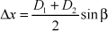
Docking is the final step for modular self-reconfigurable robots to transform between different configurations. The automatic docking procedures of the proposed modules are shown in Figure 5. In the preliminary work, we assume that all the docking operations are performed in a 2D planar surface without obstacles. During the docking process, one of the modules remains in a fixed position, and the other plugs its male connector into the female connector of the fixed modules. As shown in Figure 6, there are two IR transmitters on the female connector and two IR receivers on the male connectors, which are used to guide the modules to dock with each other. The Distance-Strength model of the IR sensors is built for measuring the relative position of two modules. In the search procedure, the male connector will find a direction of the best IR signal strength with a 5° step in the scope of ±15°. The searching step is presented in Figure 7. The distances D1 and D2 can be calculated by the Distance-Strength model when the module obtains the readings of IR sensors. The angle deviation β, the horizontal deviation Δx, and the axial deviation Δy are calculated by (1)–(3), where L is the constant distance between IRR1 and IRR2. Finally, the module aligns its position to dock with the fixed module successfully. Otherwise, it will repeat the above operations.


Automatic docking procedures of two modules

Relative position calculation of the two modules. IRT1 and IRT2 are two IR transmitters. IRR1 and IRR2 are two IR receivers.

Search procedure of the male connector
3.2 Locomotion and geometry of single module
In the docking process, the module needs to adjust the deviation β, Δx, and Δy. Therefore, a single module must have flexible mobility. The configuration of the proposed module is pitch-yaw-pitch (PYP). Four types of motion can be implemented by coordinating the three joints.
3.2.1 Rectilinear motion
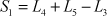
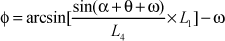
A single module can implement an inchworm-like rectilinear locomotion. The four key frames of rectilinear motion cycles are shown in Figure 8. The module is driven by the two end joints. A motion cycle is divided into four steps. As shown in Figure 9, the single module can move forwards a distance S after executing a motion cycle. The head joint makes the module move forwards a distance Si while the tail joint makes the module move forwards a distance S2. The theoretical value of the distance S can be calculated by (4)–(16).


Two-gait cycle of rectilinear motion of the single module

The geometry of the rectilinear motion
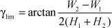
Due to the mechanical limitation, the distance S1 cannot be achieved when the tail joint angle α<α lim , as shown in Figure 9(C). The angle a lim is calculated by (17)–(19). The distance S2 cannot be achieved when the angle Φ<γ lim . The maximum theoretical distance S is 51.82 mm, which is obtained by rotating the two end joints to 60°. However, the actual distance is shorter than S due to friction between the body shells and working surfaces.
3.2.2 Lateral shift
The lateral shift locomotion includes five steps, as shown in Figure 10. In the lateral shift actions, the two end joints are raised to reduce the friction between body shell and working surface. Then lateral shift can be implemented by bending the middle joint. The geometry of this motion is shown in Figure 12. The lateral shift distance is S when the angle of middle joint is θ. The distance S can be calculated by (21)–(23). The angle α in the equations is the angle of the two end joints rotated.
Lateral shift of the single module Lateral roll of the single module The geometry of the lateral shift and lateral rolling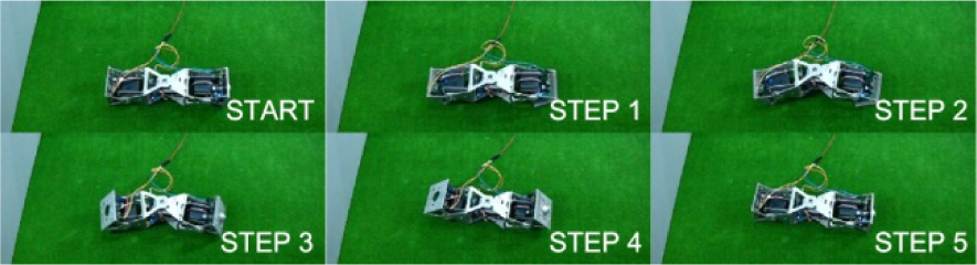


3.2.3 Lateral rolling
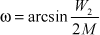
As shown in Figure 11, the module can implement a lateral rolling motion when the angle of the middle joint is large enough in the lateral shift operations. This is because the centre of mass (COM) of the module is outside of the black dashed region. In Figure 12, a rectangular plane coordinate system is defined to calculate the position of the COM. The ordinate of COM is expressed by (24). The lateral rolling action can be achieved under the condition that the ordinate of COM y is large than H (25). Therefore, we find that the angle of the middle joint must be larger than 75°.


3.2.4 Rotation motion
In the assembling process, the module needs to adjust the angle deviation between the male and female connectors. The proposed module can implement rotation motion, which is divided into five steps, as shown in Figure 13. The single module applies force to the working surface as shown in Figure 14. The force F3 is larger than F4. Therefore, the static friction force at position B is larger than that at position A. The body shell contact with position B will stay fixed when the middle joint rotates. Therefore, the rotation angle of the module is equal to the rotation angle of the middle joint, ideally.

The rotation motion of the single module

The force analysis of the rotation motion
3.3 Rotation motion of two modules
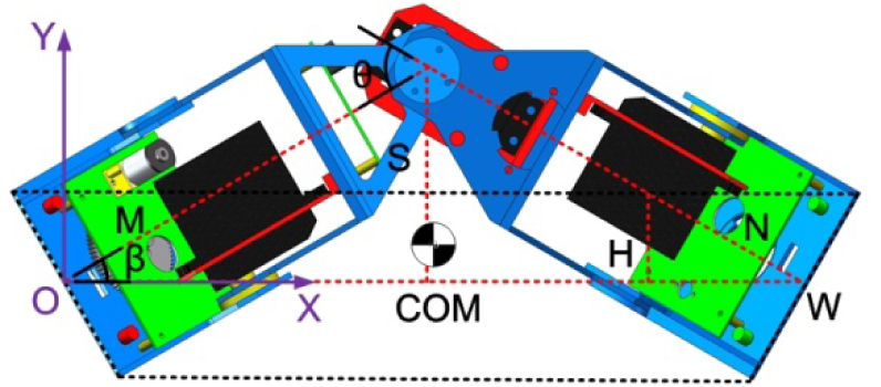
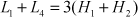
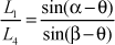
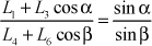
A configuration with few modules cannot perform a transformation by the kinematic method. In this paper, a detach-docking approach is proposed to implement the I-to-X transformation operation. Two assembled modules need to rotate 90° to prepare for docking in the procedures. The rotating process of the two assembled modules is shown in Figure 15. A rotation gait cycle of two assembled modules includes ten steps. The geometry of the rotation action is shown in Figure 16. The angles of the second and fifth joints are α and β respectively. The rotating angle of the two assembled modules is 0, which can be calculated by (26)–(30). γ is the angles of the first and sixth joints.


The rotation motion of the two assembled modules
The geometry of the rotation motion of two assembled modules
3.4 Locomotion planning of I-shaped configuration
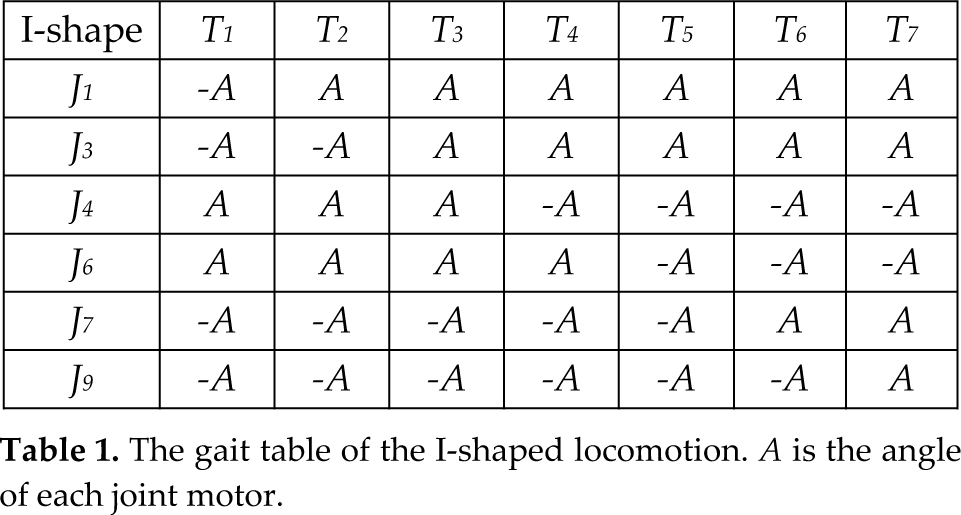
As shown in Figure 17, three modules are assembled into an I-shaped configuration. The horizontal and vertical rotation axes of each joint are not orthogonal one by one. Figure 5 presents that the I-shaped robot implements serpentine wave locomotion by coordinating the joints J i (i = 1, 3, 4, 6, 7, 9). The controlling method used here is gait table. The I-shaped robot can implement rectilinear motion when the joints J i (i = 2, 5, 8) are fixed. The negative joint angle is defined as –A when the joint arm is rolled downward. The positive joint angle is defined as A when the joint arm is raised up. The gait table of the I-shaped robot is shown in Table 1. Joint angle commands in the gait table are transmitted to microcontrollers of each joint through a wireless sensor network with fixed time interval. The joint motors are controlled to rotate to the desired positions by microcontrollers. An I-shaped robot can cycle through the gait tables as necessary for a continuous locomotion pattern.

Locomotion planning of I-shaped configuration
The gait table of the I-shaped locomotion. A is the angle of each joint motor.
3.5 Locomotion planning of X-shaped configuration
Four robot modules are assembled into an X-shaped configuration, as shown in Figure 18. The creeping motion cycle is composed of six steps. The angle of each joint is set as 0° at the initial state of locomotion. The X-shaped robot moves forwards a distance S after a gait cycle. The gait table of an X-shaped robot is presented in Table 2. The joints J i (i = 1, 3, 4, 6, 7, 9, 10, 12) are raised up to reduce the friction between body shells and the working surfaces. The distance S is largely decided by the angles of joints J i (i=2, 5, 8, 11).

Locomotion planning of the X-shaped configuration
The gait table of X-shaped creeping locomotion. A1, A2, and A3 are the angles of the corresponding joint motors.

4. Experimental results
Several experiments have been done to evaluate the performance of the proposed modular self-reconfigurable robot. Firstly, the impacts of joint angles on the motion of a single module are investigated. Secondly, the performance of the docking method is evaluated by automatic docking tests of two modules. The I-to-X transformation is also presented. Thirdly, the influences on mobility of I-shaped and X-shaped robots are figured out. Lastly, the communication system based on wireless sensor networks is tested.
4.1 Mobility of single module
The flexible mobility of a single module is needed in the docking procedure or distributed tasks. As described in Section 3, the single module can implement rectilinear motion, lateral shift, lateral rolling and rotating motion. Some mobility tests are performed to investigate the impacts of the joint angles. Then the results are compared with the theoretical values calculated in the geometry analysis. Finally, the mobility efficiencies of each locomotion pattern are given.
Figure 19 shows the influence of the joint angles on the rectilinear moving distance S. The actual maximum value is 2.4 cm per gait cycle when the angles of the two end joints are both set as 60°. But only 46% of the theoretical value is achieved. The maximum efficiency of rectilinear motion is 74% when the angle of the tail joint is 25° .

The impacts of the two end joints on the distance S by which the single module moves
The lateral shift distance S is largely decided by the angle of the middle joint angle θ. Figure 20 illustrates that the module has an angle deviation inevitably after completing a gait cycle. The average mobility efficiency can be up to 77% and the efficiency can reach up to 90% when θ is larger than 35°. However, the higher the efficiency, the larger the angle deviation.

The influence of the middle joint angle on the distance of the lateral shift
The rotation angle increases with increasing the middle joint angle
The module can also implement a rotating motion to adjust the angle deviation. Compared with the theoretical values, the actual rotation angles merely have an average efficiency of 38% in the rotation action of a single module.
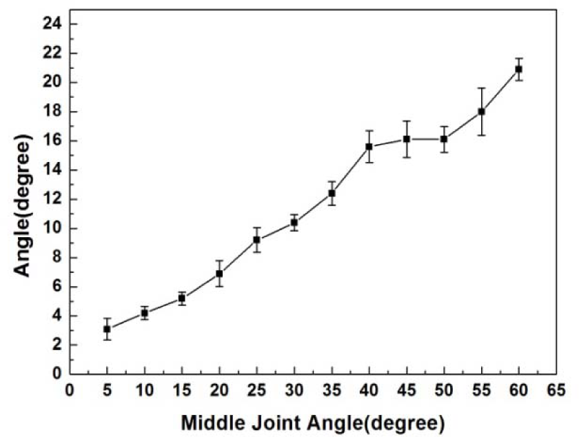
In the I-to-X transformation planning, the two assembled modules can perform a rotation action. The impacts of the second joint angle a and the fifth joint angle β on the rotation angle θ are figured out. Experimental results are shown in Figure 22. The modular robot can revolve around its centre when α is equal to β. The theoretical value of θ is approximately half of the joint angle α, β. The average efficiency of this action can reach 94%.
4.2 Self-assembly and transformations
The most prominent feature of the modular self-reconfigurable robot is that several modules can be assembled together and the robot can change its configurations according to different tasks and environments automatically. Firstly, the automatic docking tests of two modules are performed to evaluate the performance of the docking method. The test results are shown in Figure 23. The module starts from nine different positions in the effective docking region of the infrared sensors on a planar table top to execute the docking operations. The test is repeated 10 times at each position. The average success rate of the docking tests is 78%. The maximum time of the docking procedures is about 75 s. The infrared-sensor-based docking procedures presented in [29] achieve a success rate of 80%, and the docking process takes about 3 min. The docking speed is therefore improved significantly. However, compared with vision-based approaches, the docking success rate and guiding range of the infrared-sensor-based method is lower [30].

The relation between the rotation angle and the second/fifth joint angles

The automatic docking experimental results of two modules

The I-shaped assembling experiment
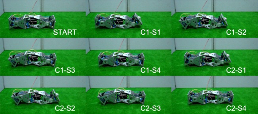
Based on the docking methods of the two modules, a detach-dock approach is proposed for the I-X transformation. The I-shaped assembling process is shown in Figure 24. In the I-to-X transformation process, two detaching operations are first triggered to separate the I-shaped configuration into three parts. The middle part turns 90° to prepare for docking. The left and right parts move towards the middle part to finish the final docking actions. The video images of the I-to-X experiments are shown in Figure 25.

The I-to-X transformation experiment

The locomotion of the I-shaped configuration
4.3 Locomotion of I-shaped and X-shaped robot
As shown in Figure 26, the I-shaped robot implements the proposed gait. The impacts of different joint angles and gait transmission intervals on the singular periodic moving distance are figured out in this experiment. The working time of each joint motor is defined as Ts, and the gait transmission interval is defined as ΔT. The working time Ts can be calculated by (31):

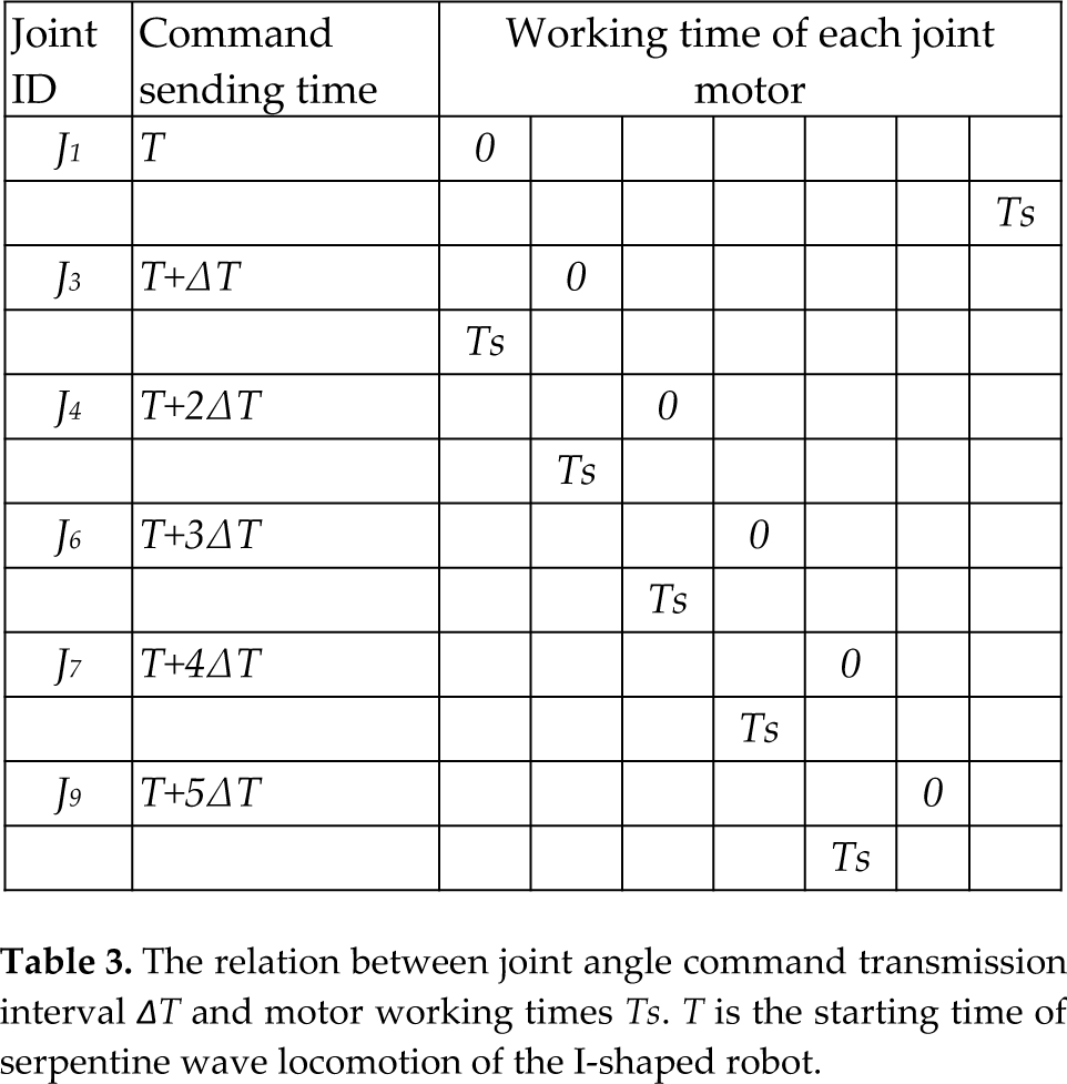
where the speed of each joint motor is 0.21 s/60°. As shown in Figure 27, the single-periodic moving distance increases with increasing the joint angles and the gait transmission interval. The moving distance increases suddenly when the joint angle is larger than 15° with 100 ms gait transmission interval, and it increases slowly when the joint angle is larger than 35° . When the joint angle is larger than 35° with 200 ms gait transmission interval, the moving distance again increases suddenly, and increases slowly when the joint angle is 60°. According to the analysis, the working times Ts of the neighbouring joints overlap when the moving distance increases suddenly, as shown in Table 3. The moving distance increases slowly when the interrelated joints are more than two. Figure 28 shows that the speed will decrease with increasing the gait transmission interval. As shown in Figure 29, the I-shaped robot can also perform a sideways locomotion by bending the vertical joints.
The relation between joint angle command transmission interval ΔT and motor working times T s . T is the starting time of serpentine wave locomotion of the I-shaped robot.
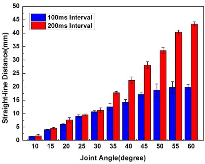
The relation between the joint angle, gait transmission interval, and moving distance

The moving speed of the I-shaped robot

The sideway locomotion of the I-shaped robot
The X-shaped robot performs a creeping locomotion, as shown in Figure 30. The impacts of the joint angle A2 on the moving distance S are illustrated by Figure 31. The distance S increases with increasing the joint angle A2. The time of a single gait cycle is 3 s. The maximum speed of the X-shaped robot is up to 4.8 cm/s.

The locomotion of the X-shaped robot

The relation of moving distance and joint angle A2
4.4 Wireless communication system
A multi-hop wireless sensor network is established for the modules to communicate with each other. As previously described, each joint is controlled by the processor, which is a ZigBee compliant wireless microcontroller. There are a lot of monitoring data, task commands and locomotion commands which need to be transferred. We carried out experiments to evaluate the performance of the wireless sensor network established by modules: we figure out the impacts of the transmission interval, packet size, and network hops on the receiving rate. As shown in Figure 32, the receiving rates reach up to 100% with the maximum packet size when the transmission interval is 25 ms and the network hop is 1. The network size is up to 1000. If each router of the network owns 10 child-nodes, the network only needs to be configured with three hops. An experiment to ascertain the receiving rate with different hops was then carried out: the receiving rates reach up to 100% with a packet size of 20 bytes when the transmission interval is 55 ms, as shown in Figure 33. This robot system is created to deploy wireless emergency networks in harsh environments. The communication distance is another important indicator. Due to the size limitation of the module, the antenna of the applied ZigBee compliant transceiver is ceramic antenna. The maximum communicating distance is about 100 m. The processor uses link quality indicator (LQI) to evaluate the received signal strength. The relation between the signal strength and LQI can be expressed by (32). It can be seen that the LQI is greatly influenced by the distance in (33). As shown in Figure 34, the receiving rate increases with LQI.


where λ is the path loss. To sum up, the proposed communication system can guarantee a 100% receiving rate when the transmission interval is 55 ms.
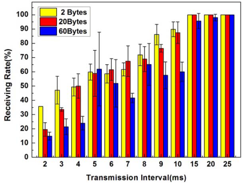
Inverse relation between the data size and the receiving rate
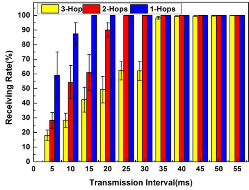
The impacts of multi-hop and transmission interval on the receiving rate. The data size is set as 20 bytes.

The impacts of the link quality and transmission interval on the receiving rate
5. Conclusion
A new modular self-reconfigurable robot has been designed and implemented in this paper. Each module can perform four types of locomotion independently by coordinating the three joints, i.e., rectilinear motion, lateral shift, lateral rolling, and rotation motion. Detailed locomotion planning and geometry analysis have been presented. A new pin-hole-based docking mechanism is designed to enable functions of self-assembly and transformation, which can provide sufficient connecting strength for the large configuration. The mechanism can tolerate misalignment errors of ±15° and ±3 cm in the docking procedures. Based on the heterogeneous connectors, an infrared-sensor based detach-dock approach was proposed for the I-X transformation. The experimental results show that the average efficiencies of rectilinear motion, lateral shift, and rotation motion are 48%, 77%, and 38%, respectively. The average efficiency of two assembled modules rotating is up to 94%. The average success rate of the proposed docking method is 78% within the effective region. Compared with other infrared-sensor-based methods, the time taken for the docking process is shortened significantly. The maximum velocity of the I-shaped robot is 3.6 cm/s, and the maximum velocity of the X-shaped robot is 4.8 cm/s.
In the future, we plan to improve the locomotion capacities of the robot and the docking success rate by using the visual guidance method.
6. Acknowledgements
The research reported in this paper was carried out at the Robotic Sensor and Control Lab, School of Instrument Science and Engineering, Southeast University, Nanjing, Jiangsu, China. The authors thank all the members of the Robotic Sensor and Control Lab for their support.
This work was supported in part by the Natural Science Foundation of China under Grant 61375076, the Natural Science Foundation of Jiangsu Province under Grant BK2011254, the Programme for New Century Excellent Talents in University under Grant NCET-10-0330, the Research and Innovation Programme for Graduate Students in Universities of Jiangsu Province under Grant CXLX13-085, and the Scientific Research Foundation of the Graduate School of Southeast University YBJJ1350.