
Abstract
Previous studies have shown low end-user acceptance of a hip disarticulation style prosthesis and that the limitations of such prostheses, including poor gait pattern, socket discomfort, weight of the prosthesis, loss of mobility, instability and high energy consumption are a contributing factor. This study was initiated to determine if a new style of prosthetic hip joint could help to overcome some of the limitations concerning the gait pattern. The present study analyzed the gait pattern of six hip disarticulation amputee subjects. The objective was to compare two different prosthetic hip joints, both from Otto Bock HealthCare: The new Helix3D and the 7E7, which is based on the Canadian model proposed by McLaurin (1954). Kinematics and kinetics were recorded by an optoelectronic camera system with six CCD cameras and two force plates. During weight acceptance, the Helix3D extends considerably slower and reaches full extension later than the 7E7. The increased range of pelvic tilt observed with hip disarticulation amputees is significantly reduced (by 5 ± 3 degrees) when using the Helix3D Hip Joint. In addition, this system showed increased stance phase knee joint flexion as well as increased maximum swing phase knee flexion angles compared to the 7E7. These motion analysis results show that the Helix3D Hip Joint can reduce gait abnormalities compared to the uniplanar design of the 7E7 hip joint.
Introduction
An adequate prosthetic fitting for those with a hip disarticulation poses a great challenge to both prosthetist and amputee. 1 Because the group of patients with amputation in the pelvic region constitutes only 1–2% of all lower extremity amputations, 2 little experience has been gained in this field to date. Less than 50% of these amputees use a prosthesis in everyday life. This low number of prosthetic fittings is described in long-term studies by Dénes and Till, 3 Fernández and Formigo, 4 Raiford 5 and Shurr. 6 This low compliance is attributed to socket discomfort, weight of the prosthesis, loss of mobility, instability and high energy consumption. 7 Focusing on the loss of mobility, the prosthetic hip joint is a major contributor to the gait pattern of these amputees. The functionality of prosthetic hip joints available to date is considered to be poor 8 and includes the following issues:
Hip extension movement is not controlled by the hip joint and a fast and uncontrolled extension motion is observed. 9,10 This may lead to problems in the spine. 10
During stance phase, the hip extends without resistance until a bumper is reached that limits hip extension. Stability of the hip joint is only reached at this time when the hip is in full extension. 9 Thus, for safety reasons the patient fully extends the hip before the contralateral foot leaves the ground.
The knee is fully extended during stance phase for stability, this is different from the normal movement. 11,12
Less knee flexion during swing phase can be observed, 1 this is different from the normal movement. 11
The hip starts flexing late in swing phase, contrary to the early flexion of the contralateral side. 9,13
The gait pattern shows an increase in pelvic tilt. 1,13,14 This extreme movement of the pelvis may cause problems in the spine. 10
All hip joints developed after the creation of the Canadian hip disarticulation prosthesis 15 have monocentric or polycentric constant friction designs while hydraulic or pneumatic control is missing. These design limitations provide limited control of stability during weight acceptance and are unable to substantially improve either the initiation of knee flexion for swing phase or the peak knee flexion angle achieved during swing phase. Therefore, further development of prosthetic hip joints is essential in order to increase the quality of prosthetic fittings for hip disarticulation and hemipelvectomy amputees.
The new Helix3D Hip Joint (Otto Bock HealthCare GmbH, D) has been available since 2008. It was developed to improve the gait pattern of amputees provided with a hip disarticulation style prosthesis, and uses hydraulic control, a polycentric joint design and flexion assist springs.
The study was conducted to verify whether the gait characteristics described above could be improved when using the Helix3D Hip Joint compared to a conventional free motion, single axis hip joint. For this purpose, the gait patterns of six hip disarticulation amputees walking with both the Helix3D Hip Joint and the 7E7 hip joint (Otto Bock HealthCare GmbH, D) were analyzed with a special focus on hip, knee and pelvic movement patterns. Based on the results, the functional benefits to the amputee were evaluated.
Methods
Subjects
Six unilateral, hip disarticulation subjects were recruited for this study. All patients were experienced prosthetic users walking with their prosthesis all day. Only the oldest subject was using a walking aid on the contralateral side in daily life and during the measurements. To participate in the study, the following was required: a properly fit hip disarticulation style socket, a C-Leg® prosthetic knee joint and either a 7E7 or Helix3D Hip Joint. Details on the subjects and their everyday fitting are listed in Table I.
All of the patients were aware of the possible risks and informed consent was obtained from each subject. This study was conducted in agreement with the guidelines of the Georg August University of Göttingen Ethics Committee. Data of healthy subjects from an earlier investigation 16 were used for comparison.
Patients' data in the study of gait patterns of six hip disarticulation amputee subjects.
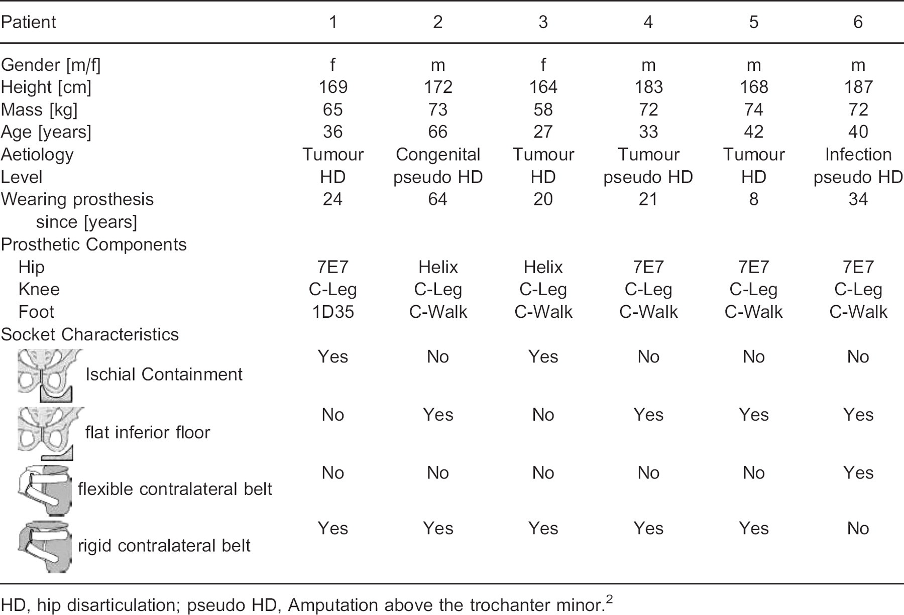
HD, hip disarticulation; pseudo HD, Amputation above the trochanter minor. 2
Prosthetic components
The C-Walk (Otto Bock HealthCare GmbH, D) 17 was selected as the foot component and the C-Leg (Otto Bock HealthCare GmbH, D) 18 as the knee component for the measurements. The 7E7 (Otto Bock HealthCare GmbH, D) and the Helix3D (Otto Bock HealthCare GmbH, D) were used as hip joints (Figure 1a).
7E7 hip joint
The 7E7 was chosen as a representative conventional hip joint. It is a constant friction, single axis hip joint. It is provided with a hip extension bumper to limit hip extension. The hip joint allows control of thigh extension by tensioning the spring integrated in the upper joint section. In this manner, the range of hip flexion during ambulation may be restricted. In addition, with the majority of amputees, the step length is limited by an elastic webbing running dorsally from the socket to the proximal tube adapter. For the subjects whose everyday prosthesis consisted of such a piece of webbing, it was also used during the measurements with the 7E7.
Helix3D Hip Joint
The Helix3D Hip Joint is a four-bar-linkage joint with a hydraulic unit that provides controlled resistance to motion during both stance and swing phase. In stance phase, hydraulic resistance controls the extension motion of the hip joint and this allows the amputee to comfortably extend the prosthetic hip while the contralateral limb is in swing phase. During swing phase on the prosthetic side, flexion is controlled by the hydraulic system as well. The time at which swing phase damping is activated and the intensity of damping are adjusted independently from each other, permitting precise adaptation of the step length. 8,19
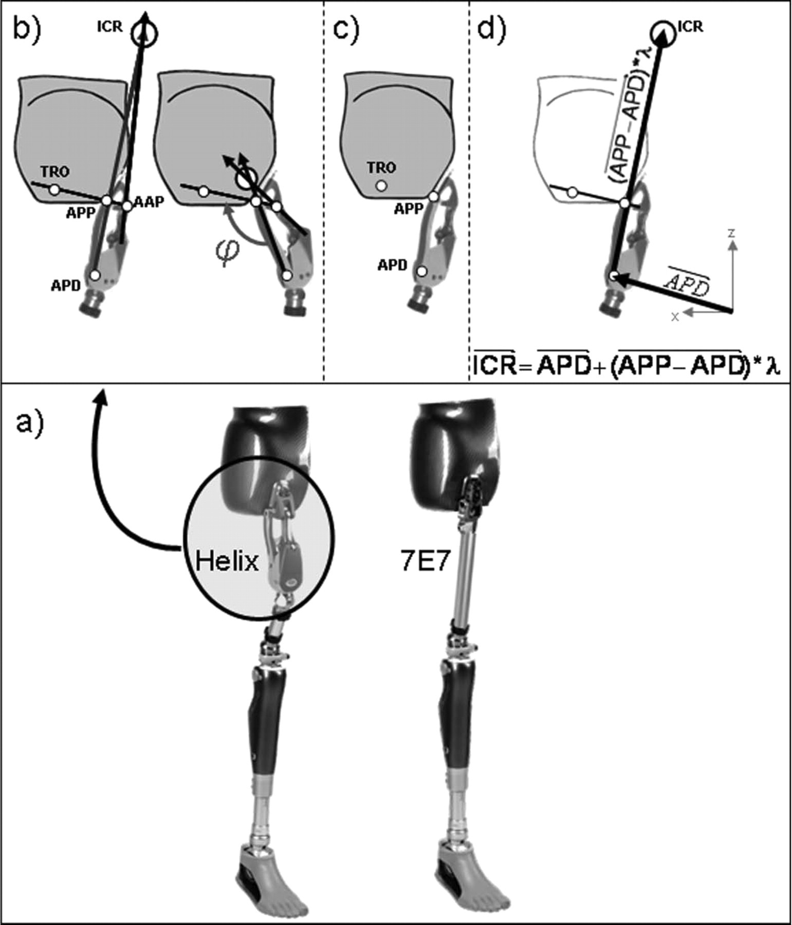
(a) Test prostheses; (b) general definition of the instantaneous centre of rotation (ICR); (c) Positions of the reflective markers on the amputee side; (d) definition of the instantaneous center of rotation (ICR) during measurement. ICR, Instantaneous Center of Rotation; APP, Axis Posterior Proximal; AAP, Axis Anterior Proximal; APD, Axis Posterior Distal; TRO, marker on the socket in order to replace a marker on the AAP.
Furthermore, the hip has two flexion assist springs. During stance, the springs are elongated and store energy. As soon as the prosthesis is unloaded, the springs return the stored energy and flex the hip joint. In addition due to axle geometry and a universal bearing, this polycentric hip joint creates triplanar movement: external hip rotation during flexion and internal hip rotation during extension, in order to compensate for pelvic rotation while walking. A total of approximately 6 degrees of rotation can be expected. 8
Test procedure
Investigations for each subject were conducted over two days and started with the 7E7 or the Helix3D in random order. The patients used only one hip joint each day, so that they could better acclimate to the selected system. During the measurements, the patients used their own sockets.
The alignment corresponds to the manufacturer's instructions for all components. 19 All alignment and adjustment parameters were verified by an experienced and qualified prosthetist. For both hip joints the resultant static situations defined on the L.A.S.A.R. Posture 20 under load were documented. The load line was positioned 66 ± 12 mm (7E7) and 54 ± 6 mm (Helix3D) anterior to the ankle adapter screw, 35 ± 7 mm (7E7) and 30 ± 1 mm (Helix3D) anterior to the knee joint axis as well as 4 ± 5 mm anterior (7E7) and 13 ± 10 mm posterior (Helix3D) to the load balance point (TMS) of the amputated side. This TMS is a reference point where the weight line of the amputated side runs through the socket. The description of the procedure to define this TMS can be found in the Otto Bock instruction manual. 19
Motion analysis was used to determine gait parameters during level walking at self-selected walking speed. In the middle of the 12 m walkway, two force plates (Kistler, Winterthur, CH) were positioned to measure the ground reaction forces for both sides during one gait cycle. Kinematic values were defined by six optoelectronic cameras (VICON, Oxford Metrics, UK). These cameras determined the coordinates of reflective markers indicating relevant points on the prosthesis and the amputee's anatomical pattern. Figure 2 indicates the position of the 23 markers.
The externally produced sagittal moments investigated in this study were calculated based on ground reaction forces and coordinates of joint axes according to the method described by Schmalz. 21 Because the 7E7 and the C-Leg are monocentric joints, the joint axis in the sagittal plane is suitable as a reference point for the external moments. This does not apply to the Helix3D Hip Joint. Due to its polycentric design, the externally produced hip moment must be determined in relation to its Instantaneous Centre of Rotation (ICR). The intersection of two vectors corresponds to the ICR: One vector is placed through the two anterior hip joint axes and a second through the two posterior ones (Figure 1b).
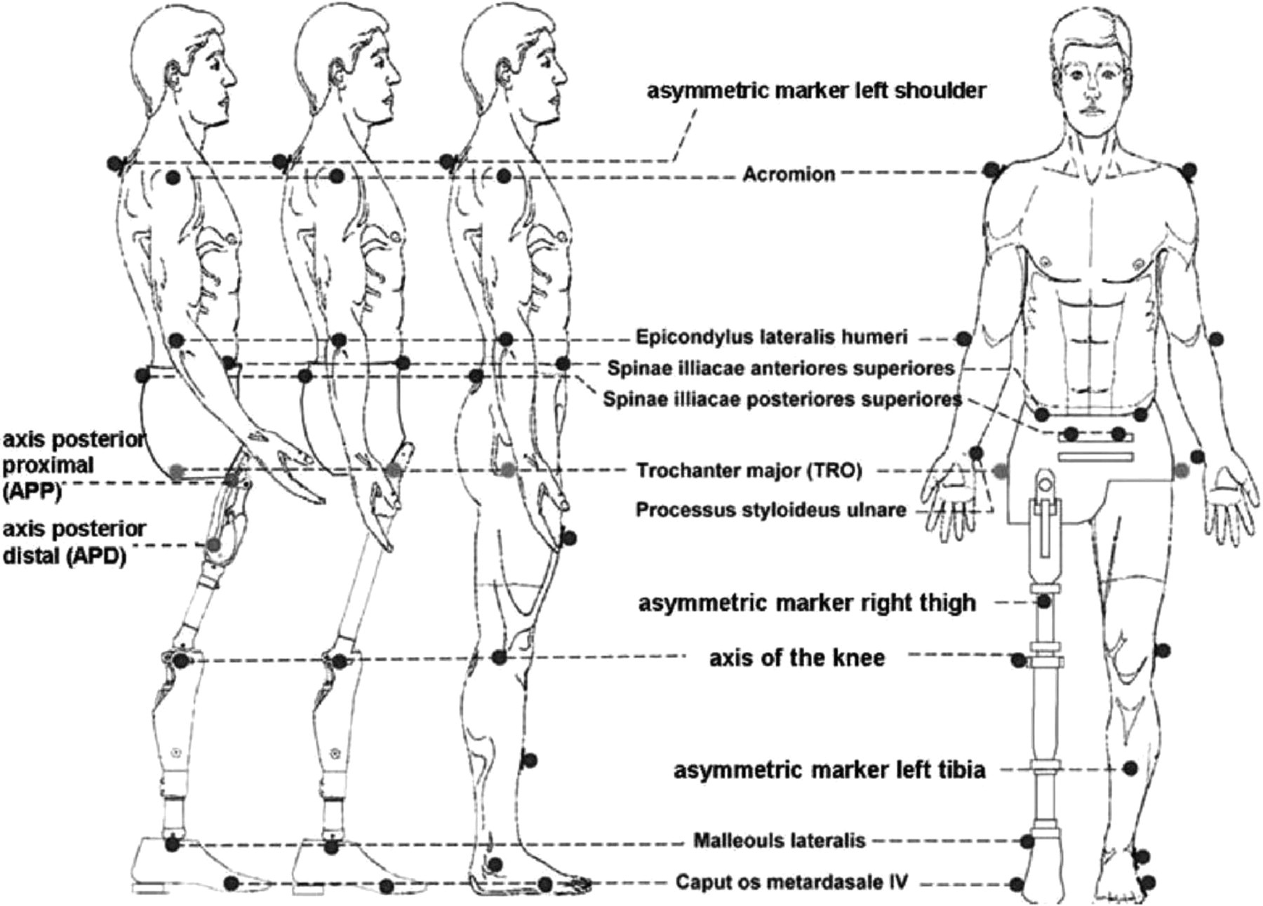
Positions of the reflective markers.
To define the ICR, a special combination of three markers was attached to determine the coordinates in the sagittal plane (Figure 1c). Because of the small distance between the axes, it was not possible to set markers on all of the axes. To overcome this obstacle, we previously used ProE® software (Parametric Technology Corporation, US) to define the coordinates of the ICR and of the four axes depending on the hip angle (ϕ). This hip angle is shown in Figure 1b and is defined as the angle between the vector through the Axis Posterior Distal (APD) and Proximal (APP) and the vector through the Axis Posterior Proximal (APP) and Anterior Proximal (AAP). During gait analysis we use a marker on the socket (TRO) in order to replace a marker on the Axis Anterior Proximal (AAP). This TRO marker was placed on the vector between the APP marker and the Axis Anterior Proximal (AAP) (Figure 1b). Thus during gait analysis no marker was set on AAP (Figure 1c).
Due to the frontal plane tilt of the axis in this hip joint, the ICR lies at most 1.26 mm from the vector between the Axis Posterior Distal (APD) and Axis Posterior Proximal (APP). We disregard this deviation and expect that the ICR is lying on this vector. This means that the coordinates of the ICR can be defined by the multiplication of the vector between APD and APP and a factor which depends on the hip angle. By means of the ProE® data, we found this correlation between the factor and the hip angle (ϕ). Thus the approximation of the coordinates of the ICR in the sagittal plane is the following equation:
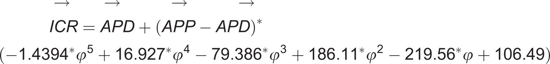
For each gait parameter, a representative mean value was determined based on nine single measurements of walking trials conducted per subject. The charts cited in the following section show the mean curves for all subjects normalized to the gait cycle of the prosthetic side. Statistically significant differences were identified by recording peak values determined in the non-parametric Wilcoxon test with a confidence limit of p < 0.05 or p < 0.01.
Results
Time-distance-parameters
During the measurements, the amputees moved at mean walking speeds of 1.07 ± 0.24 m/s (7E7) and 1.08 ± 0.21 m/s (Helix3D). The step length on the prosthetic side ranged between 0.69 ± 0.12 m (7E7) and 0.65 ± 0.07 m (Helix3D). On the contralateral side, the step length tended to be higher with both fittings reaching mean values between 0.71 ± 0.07 m (7E7) and 0.70 ± 0.04 m (Helix3D). The differences between both joints were insignificant (p = 0.75 [velocity], p = 0.35 [prosthetic step length], p = 0.46 [contralateral step length]).
Pattern of the hip joint
With all subjects using the Helix3D, the external hip moments produced during stance were extension moments (Figure 3a). Walking with the 7E7, however, a short flexion moment within the first 20% of the gait cycle could be observed with five subjects. The resultant mean value differs significantly (p = 0.046) from the extension moment seen in the Helix3D within this period (Figure 3b).
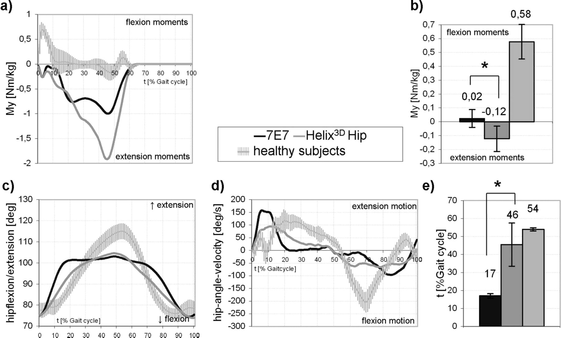
(a) Mean pattern of sagittal hip moments; (b) Mean maximum sagittal hip moments within the first 20% of the gait cycle; (c) Mean pattern of hip flexion/extension; (d) Mean pattern of hip angle velocity; (e) Mean time of maximum hip extension (tMHE); ∗significant, p < 0.05.
The pattern of hip angle (Figure 3c) and hip angular velocity (Figure 3d) for both hip joints shows differences. With the 7E7, maximum extension is reached at 17% of the gait cycle and thus significantly (p = 0.028) earlier than with the Helix3D which reaches extension at 46% of the gait cycle (Figure 3e). Until flexion is initiated after 70% of the gait cycle, the hip angle of the 7E7 changes only slightly. With the Helix3D, however, flexion starts again immediately after maximum extension. At first the hip anglular velocity of the 7E7 (Figure 3d) increases steeply until the global maximum of 160 ± 45 deg/s is reached at 8% of the gait cycle. With the Helix3D this value rises more moderately and the maximum angular velocity of 94 ± 20 deg/s is reached after approximately 12% of the gait cycle. This is a significant reduction compared to the 7E7. Following this, the flexion velocity rises. This is represented by the downward slope of the graph on the y-axis where a greater negative number represents a higher flexion velocity. Thus the curves show peak flexion velocities of −98.5 deg/s (7E7) and −64 deg/s (Helix3D) and this results in a significant difference (p = 0.028).
Pattern of the knee joint
In the first 20% of the gait cycle, the knee moments (Figure 4a) of the prostheses are qualitatively and quantitatively different. Throughout the first 20% of the gait cycle knee flexion moments are shown with the Helix3D. With the 7E7 only a short flexion moment is produced between both 0 and 5% and between 15 and 25% of the gait cycle. After this both prostheses have only knee extension moments during stance.
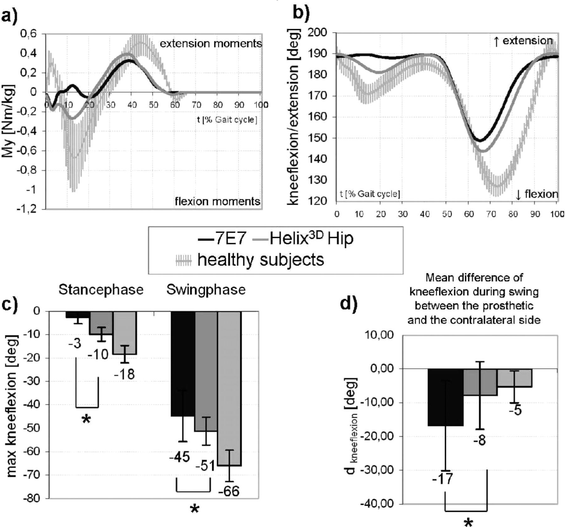
(a) Mean pattern of sagittal knee moments; (b) Mean pattern of knee flexion/extension; (c) Maximum knee flexion during stance and swing phase; ∗significant, p < 0.05; (d) Difference of the maximum knee flexion during swing of the sound and the prosthetic side (dkneeflexion); ∗significant, p < 0.05.
Thus the pattern of knee motion (Figure 4b) differs markedly as well. When walking with the prosthesis provided with the Helix3D, increased stance phase flexion (10 ± 3 degrees) of the knee joint can be observed when compared to the 7E7. With the 7E7, stance phase knee flexion is significantly (p = 0.028) reduced (Figure 4c, left). Besides the differences in stance, the mean knee flexion during swing phase with the Helix3D Hip Joint System is 51 ± 6 degrees and this is a significant (p = 0.046) increase when compared to the 45 ± 11 degree value (Figure 4c, right) measured with the 7E7.
Hence, the difference in swing phase knee flexion between the prosthetic and the sound side is significantly decreased (p = 0.028) by using the Helix3D Hip Joint (Figure 4d).
Pattern of pelvic tilt
In the first 20% of the gait cycle, pelvic posterior tilt can be observed for both hip joints (Figure 5a). Then for both hip joints the pelvis tilts anteriorly until about 50% of the gait cycle and then posteriorly until about 75% of the gait cycle. At 75% of the gait cycle with the 7E7, the pelvis again tilts anteriorly; however, this only lasts until approximately 90% of the gait cycle at which time the pelvis tilts posteriorly until the end of swing phase. With the Helix3D, from 75% of the gait cycle to the end of swing phase the pelvis only tilts anteriorly.
The maximum mean range of pelvic tilt of 25 ± 4 degrees measured with the 7E7 between 0 and 50% gait cycle is significantly (p = 0.028) increased when compared to the 20 ± 4 degrees measured with the Helix3D (Figure 5b).
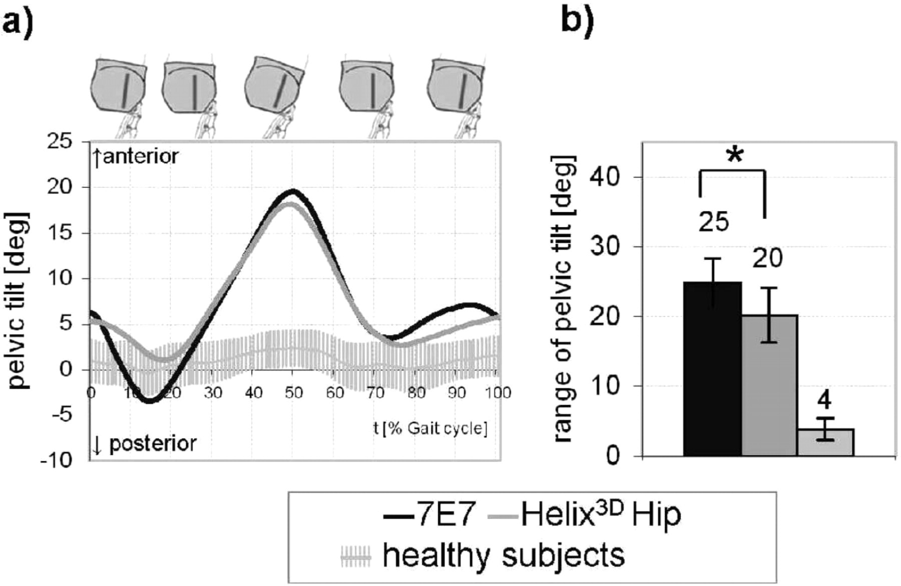
Pelvic tilt; (a) Mean pattern; (b) Mean range of pelvic tilt; ∗significant, p < 0.05.
Discussion
The results of motion analysis suggest that the functional difference between the Helix3D and a conventional hip joint influences the typical amputee's gait pattern as described in the introduction. With healthy subjects, nearly the whole stance phase is characterized by hip flexion moments. Hip disarticulated amputees are not capable of compensating these moments by muscular activity. Therefore prosthetic treatment aims at generating hip extension moments during the whole stance phase by means of structural and functional design and positioning of the hip joint component. Beside the functional significance this is also a safety-relevant aspect.
Within the first 20% of the gait cycle, i.e., at weight acceptance, the 7E7 produces hip flexion moments which can lead to instabilities. With the Helix3D, however, increased hip extension moments acting during the entire stance phase offer the amputee increased stability and thus a higher safety potential than is offered by the 7E7.
Although the Helix3D is not fully extended during this time, the hip has increased stability because of the larger distance between the ground reaction force and the ICR (which is located anterior and superior). Hence in contrast to other systems, the Helix3D achieves higher stability without attaining full extension. 9
The pattern of hip angular motion and angular velocity with the Helix3D is, when compared to other systems, qualitatively more similar to the hip motion observed in non-amputees. 22–24 With the 7E7, the hip angle extends in early stance phase with increased angular velocity and reaches the extension stop very quickly, as described in the literature. 9,10 Due to its adjustable resistance, hip extension with the Helix3D is performed more slowly and reaches maximum extension at a time which corresponds to approximately 54% of the gait cycle of able-bodied people. 22–24
This leads to the conclusion that the hip joint is continuously moving during single limb support on the prosthetic side and this is more in line with the hip motion of the contralateral limb. This effect is achieved because of the hydraulic control of the Helix3D compared to the constant friction control of the 7E7. The amputees describe this movement as very comfortable and they specify that they feel the rotation of the hip during this extension. It is described as a feeling of being lead by the prosthesis and as being especially advantageous. 8
With the 7E7, once the hip starts flexing, the hip flexion angular velocity remains very low until the knee begins to extend. 9,13 At this time the hip flexion angular velocities rapidly change and are significantly increased. From 83–100% of the gait cycle, the direction of motion changes and the hip joint starts to extend before weight acceptance. Thus, a posterior motion of the leg as a pendulum is observed at the end of swing phase on the prosthetic side. The hip flexion angular velocities of the Helix3D analyzed during swing phase are more constant from the beginning of flexion movement until flexion is completed. The posterior motion of the entire limb is not seen when the Helix3D is used. This confirms that the swing phase damping of the hip joint performs effectively and this behavior is more consistent with the contralateral limb.
When using the Helix3D Hip Joint, the released energy of the flexion assists springs cause a significant increase in the maximum knee flexion angle during swing phase when compared to the 7E7 (Figure 3c). This helps to minimize asymmetrical knee flexion between the prosthetic and contralateral sides (Figure 3d). Even though the Helix improves the knee angle for swing phase, it is still much lower than healthy subjects.
With regards to knee motion, differences of joint-specific patterns can be identified not only when referring to the maximum angle in swing phase, but also when observing stance phase flexion of the prosthetic knee. This knee movement is caused by external sagittal knee flexion moments. Stance phase knee flexion is only seen sporadically and with a low knee flexion angle when using the 7E7. When walking with the Helix3D, knee flexion during stance phase is significantly increased. The application of the Helix3D hydraulic mechanism during extension and the tensing of the flexion assist springs seem to provide the external knee flexion moments that produce more consistent periods of stance phase knee flexion with a peak at approximately 20% of the gait cycle. This influence on the knee moments by a hip mechanism was already observed in a previous study. 25 That study used a hip joint with similar flexion assist springs that compressed during stance phase.
The stance phase damping of the Helix3D allows the amputee to extend the hip joint more slowly and to control the pelvic posterior tilt. Hence in early stance phase, pelvic posterior tilt is clearly mitigated and this is followed by maximum pelvic anterior tilt at a later time. Thus, the range of this movement is reduced.
Compared to non-amputees, which have a normal range for anterior/ posterior tilt of 4 degrees, 22,23 the range of pelvic tilt observed with hip disarticulation amputees is generally, both with the 7E7 and with the Helix3D Hip Joint, significantly increased. 1,8,13,14 The reduced range of motion observed in the anterior/posterior tilt when wearing the Helix3D Hip Joint System could help alleviate spinal pain symptoms and requires further study of its benefits.
Conclusion
The results of this investigation confirm significant enhancements with regards to the gait pattern of hip disarticulation patients when walking with the new Helix3D Hip Joint in comparison to the 7E7 hip joint.
These enhancements include:
Improved hip extension control and polycentric design offer increased security during stance phase with respect to uncontrollable hip motion;
Longer, more natural period of hip extension during stance phase;
More constant hip flexion movement during swing phase;
Increased knee flexion during stance phase;
Increased knee flexion during swing phase;
Significant reduction in the range of pelvic tilt.
Hence, the Helix3D Hip Joint System provided a gait pattern more similar to that of able bodied persons than the uniplanar 7E7 design.
Acknowledgements
The authors gratefully acknowledge Annett Elsner (Otto Bock HealthCare GmbH, Duderstadt) and Greg Schneider (Otto Bock HealthCare GmbH, Minneapolis) for their valuable contributions to the preparation of this manuscript.