
Abstract
Assessment of damage to homes following a significant earthquake has found that the primary reason for major structural damage and failure is due to inadequate lateral bracing of cripple walls and inadequate sill bolting of the cripple wall to the foundation. Since the 1970s, methods to retrofit weak cripple walls and improve sill anchorage have been developed and implemented on many dwellings to improve their seismic performance, most notably available are the Federal Emergency Management Agency (FEMA) P-1100 guidelines. To assess the seismic vulnerability of existing and retrofitted cripple walls, experimental programs were performed and documentation of the evolution of damage during these experiments were produced and correlated to the structural capacity and residual drift of the specimens. Using the documented damage evolution, existing damage fragility functions were revised for wood light-frame sub-assemblies. In this article, an overview of the cripple wall experimental program is provided, including the variables investigated. Documentation of the damage evolution during these experiments is presented. Damage states based on repair triggers associated with imposed displacements of the experiments are defined. Finally, a discussion of how the damage observations were used to develop probabilistic component-level damage fragility functions for cripple-wall dwellings is provided.
Introduction
Field observations from past earthquakes have shown that inadequate lateral bracing of cripple walls and insufficient sill anchorage lead to moderate to major structural damage in single-family, wood-frame dwellings. The extent of damage has been shown to be directly related to the era of construction of the dwelling, the exterior finish type, the number of stories location of the dwelling, with those on hillsides and in high-seismicity locations being more adversely affected (e.g. EERI 1996; Kang and Mahin, 2014; Mahin, 1991). These vulnerabilities and the high likelihood of earthquakes in California have led to a push to develop state-of-the-art retrofit prescriptions and implement them on the susceptible housing stock.
At the start of 2013, the Federal Emergency Management Agency (FEMA), the Applied Technology Council (ATC), and the California Earthquake Authority (CEA) jointly funded a project to develop a prestandard retrofit design prestandard for single-family wood light-frame dwellings (Blaney et al., 2018). Their findings were published in 2018 as FEMA P-1100: Vulnerability-Based Seismic Assessment and Retrofit of One- and Two-Family Dwellings (FEMA, 2018). For crawlspace dwellings, the FEMA P-1100 retrofit method consists of adding wood structural panels to cripple walls, anchor bolts to sill plate–foundation interfaces, and shear clips to cripple wall–first floor interfaces to properly brace cripple walls and transfer lateral loads to the foundation. Despite the availability of this prestandard, an experimental basis for the new detailing prescriptions is lacking.
To this end, the Pacific Earthquake Engineering Research Center (PEER) project, with the support of CEA, undertook an experimental program executed at the University of California, Berkeley (UCB) and the University of California, San Diego (UC San Diego). UC San Diego’s program consisted of testing cripple-wall only assemblies, herein referred to as the small-component testing program (Schiller et al., 2020b, 2020c, 2020d), and UCB’s program consisted of testing cripple-wall and first-story assemblies and is therefore referred to as the large-component testing program (Cobeen et al., 2020). Comparison of the small- and large-component test program is provided in a companion paper (Schiller et al., 2022), while this article primarily uses data and observations from the small-component test program.
The small-component program consisted of 28 cripple-wall-only specimens, with 27 tested using a reversed cyclic displacement-controlled lateral loading protocol and 1 specimen tested under a monotonic displacement-controlled protocol. These tests focused on assessing specimen performance considering variations of cripple wall finish materials, retrofit condition, cripple wall height, boundary conditions, anchorage condition, and vertical loading. Measurements during tests were used to generate global hysteretic response of the assemblies, characterize specimen deformation, document anchor bolt load histories, and record other measurements useful in quantifying the damage evolution of the assemblies. In addition, extensive video and photo documentation was taken throughout the tests, which provides a basis for comparing observable damage characteristics to the strength, imposed displacement, and residual displacement of the specimens. Both the analog data and the digital documentation were used to develop a standard for defining damage states and their associated repair triggers. Correlations between damage state and imposed transient displacements were then used to develop loss models of dwellings (Welch and Deierlein, 2020). This work produced a basis for determining the benefits of a seismic retrofit in terms of both reduced damage and reduced costs of repair to the dwelling by quantifying both the performance of existing and retrofitted dwellings and making a comparison between the two.
In the following sections, an overview of the small-component experimental program is provided, including the main variables investigated. In addition, a description of the FEMA P-1100 prescriptive design provisions is given and their implementation in tests is described. Following this, a detailed evolution of damage as observed during these tests is provided. The damage evolution is used to correlate the imposed displacements of the experiment to the observable damage characteristics related to specific damage states. Finally, a discussion of how the experimental damage observations are used to develop probabilistic damage fragility functions to relate the response of cripple-wall sub-assemblies to different damage states is presented.
Experimental program overview
In total, 28 full-scale cripple-wall-only assemblies were tested in the small-component test program. Variables of interest in this program were identified using representative “Index Buildings” and their associated variants (Reis, 2020). Namely, variants were formulated based on (1) parameters which would have a significant effect on the seismic response of the building and (2) parameters which have a statistically significant presence in California’s housing stock, and (3) amount of damage reduction possible should the cripple wall be retrofit. In addition, the variant must be observable to be quantified with damage and loss functions.
Considering these criteria, the main variables considered in the small-component testing program include exterior finish materials, retrofit condition, cripple wall height, imposed axial load, anchorage condition, and cripple wall boundary conditions. The exterior finishes tested were either a dry or wet (stucco) finish, often in combination with sheathing materials. The wet exterior finishes included stucco over framing, stucco over horizontal lumber sheathing, and stucco over diagonal lumber sheathing, while the dry exterior finishes included horizontal ship-lapped lumber siding over framing, horizontal ship-lapped lumber siding over diagonal lumber sheathing, and T1-11 wood structural panels. Figure 1 shows the interior and exterior isometric views of the various finishes of specimens in the small-component testing program.
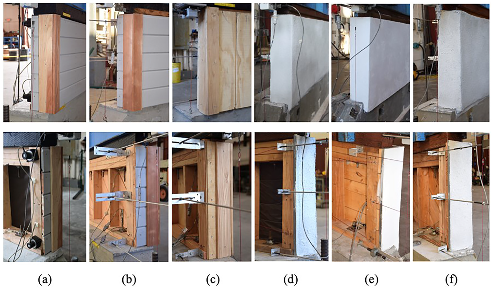
Exterior and interior isometric views of cripple-wall-only assemblies. (a) Horizontal siding over framing. (b) Horizontal siding over diagonal sheathing. (c) T1-11 wood structural panels. (d) Stucco over framing. (e) Stucco over horizontal sheathing. (f) Stucco over diagonal sheathing.
The retrofit condition included existing (also referred to as unretrofitted) cripple walls and cripple walls retrofitted in accordance with the FEMA P-1100 prescriptive retrofit design (FEMA, 2018). The two heights of cripple walls tested were 2- and 6-ft tall, representing an upper and lower bound of cripple wall heights found in California’s housing stock. In addition, heavy and light axial loads were considered. An overview of the test setup, presenting as an example a 2- and 6-ft-tall specimen, and each of a heavy and light axial load setup, is shown in Figure 2. Additional details of the test setup, including a detailed test matrix, for the small-component tests can be found in Schiller et al. (2020a, 2020b, 2020c, 2020d, 2021).
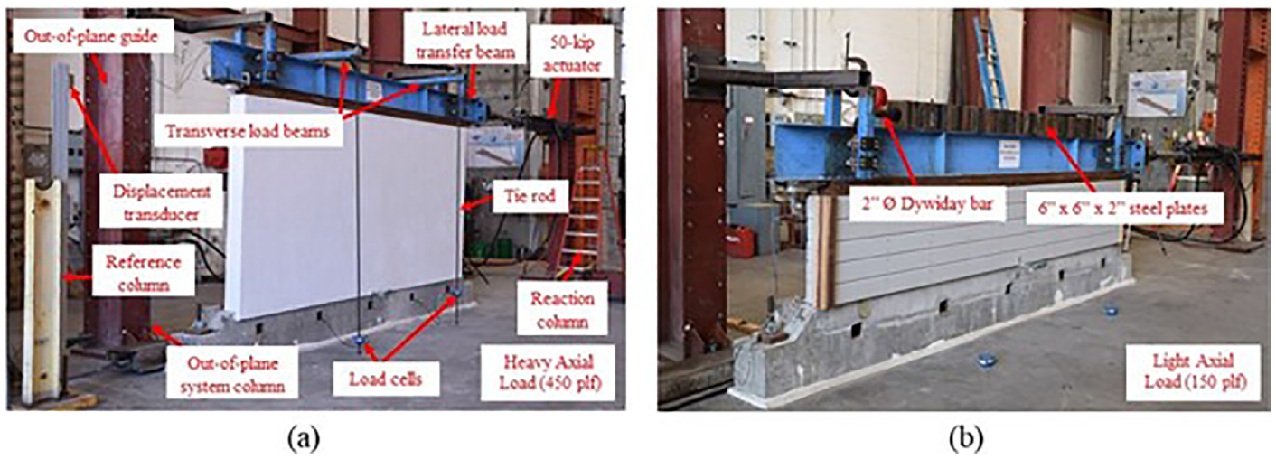
Small-component test setup. (a) 6-ft tall, heavy axial load. (b) 2-ft tall, light axial load.
The FEMA P-1100 prescriptive design prestandard was the basis for implementing the retrofit condition on the cripple walls in this test program. This design methodology takes into consideration the dwelling’s weight classification, number of stories, cripple wall height, and square footage and the seismicity of the dwelling’s region. In the present investigation, based on the index building designs and use of the FEMA prescriptions, retrofitted cripple walls were sheathed for 100% of their length with 15/32-in plywood and edge-nailed with 8d common nails at 3-in on center. Four additional anchor bolts were added to the retrofitted cripple walls. Additional information regarding the retrofit details can be found in Schiller et al. (2022).
All tests performed were displacement-controlled with loading imposed by hydraulic actuators. The loading protocol for the large-component and small-component tests generally followed the same methodology, which involved an extension of early concepts of the CUREE-CalTech load protocol work of Krawinkler et al. (2001). Considering more specifically the behavior of cripple walls, the present protocol adopted was developed by Zareian and Lanning (2020).
Evolution of damage: physical observations, repair triggers, and drift demands
Damage documentation was collected throughout testing using high-resolution photographs, examination of video footage from testing, and detailed hand notes. Using data from the 28 cripple-wall-only and two large-component cripple wall tests, trends in physical damage characteristics are correlated with the specimen drift demand.
The largest attributors to observable physical damage could be categorized based on the exterior finish style and retrofit condition of the cripple wall. For the existing and retrofitted wet finished specimens, the most notable damage observations included stucco cracking, nail withdrawal/rotation, plywood panel tearing/rotation, and uplift/splitting of framing members. For the existing and retrofitted dry finished specimens, finish and plywood nail withdrawal/rotation, plywood panel tearing/buckling, and rotation/uplift/splitting of framing members were observed. In addition, for cripple walls with diagonal sheathing, it was common to observe fracturing of the anchor bolts and cross-grain splitting on the sill plate, which led to the failure of the cripple wall. In what follows, the evolution of damage for wet and dry finished specimens and damage to components added in accordance with the FEMA P-1100 prescriptive retrofit design are presented. Within these subsections, further discussion of damage evolution specific to cripple wall height, anchorage condition, and axial load is of focus. Along with documentation of the evolution of damage, the associated transient and residual drifts for each damage state are defined for the various types of cripple walls. The definitions of the damage states are in accordance with the FEMA P-58 methodology with modifications adopted based on experimental observations.
Adopting FEMA P-58, structural engineering demand parameters are translated to damage states for both structural and nonstructural components using component-level damage fragility functions. Note that the number of damage states for each material type depends on the number of distinct levels of repair effort required to restore the wall assembly to pre-event conditions. The descriptions of the damage states are derived from both FEMA P-58 (FEMA, 2012b) and CUREE EDA Repair Guidelines (CUREE, 2010) where applicable.
Wet finished specimens
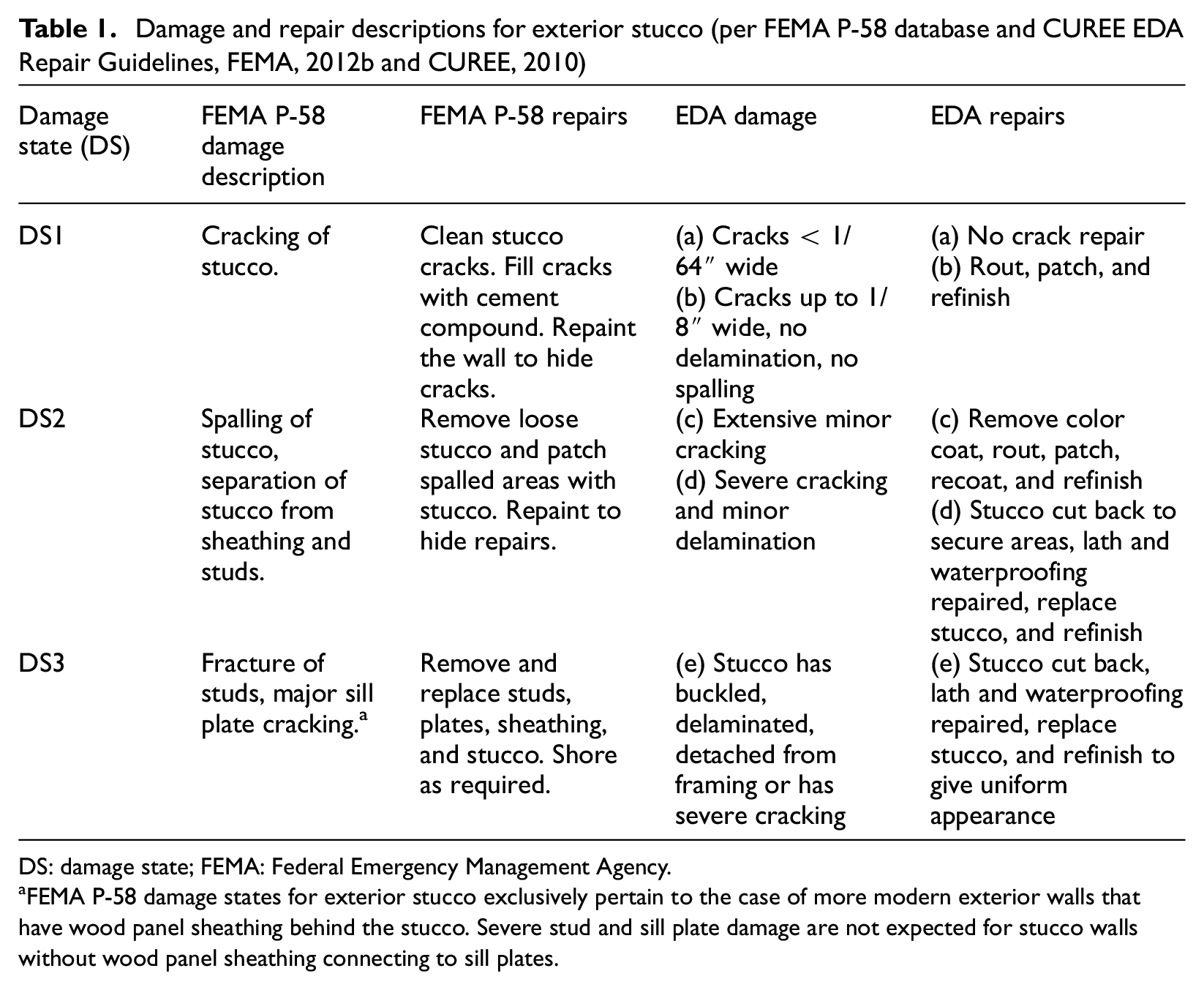
Wet (or stucco) finished specimens accounted for 17 of the 28 small-component specimens within the small-component test program. Of these 17 specimens, 5 were constructed with the FEMA P-1100 prescriptive retrofit. Likewise, 10 specimens were finished with stucco over horizontal sheathing, 5 finished with stucco over framing, and 2 finished with stucco over diagonal sheathing. Two of the wet finished specimens were 6-ft tall (both finished with stucco over framing), and all others were 2-ft tall. For the large-component testing program, both cripple-wall first-floor assemblies were 20 by 4 ft in floor plan and 2-ft-tall, constructed with wet finishes, with one in the existing condition (AL-1) and one in the retrofit condition (AL-2). The two large-component tests were finished with stucco over horizontal sheathing, and they were identical in all other details. The construction details for the cripple wall of AL-1 were most akin to small-component test A-20. Table 1 provides descriptions of damage states and their associated repairs for walls with stucco exterior finishes based on FEMA P-58 (FEMA, 2012b) and the CUREE EDA Repair Guidelines (CUREE, 2010). These descriptions are used for all types of wet finished cripple walls as they are derived from observable damage which would be seen from the exterior of the cripple wall where the stucco is visible and the sheathing is not.
Damage and repair descriptions for exterior stucco (per FEMA P-58 database and CUREE EDA Repair Guidelines, FEMA, 2012b and CUREE, 2010)
DS: damage state; FEMA: Federal Emergency Management Agency.
FEMA P-58 damage states for exterior stucco exclusively pertain to the case of more modern exterior walls that have wood panel sheathing behind the stucco. Severe stud and sill plate damage are not expected for stucco walls without wood panel sheathing connecting to sill plates.
Results from the small- and large-component testing provide insight regarding the relative drift imposed on the cripple-wall specimens, which led to the aforementioned damage states. It should be noted that the relative drift, herein referred to simply as drift, is the displacement imposed only over the height of the cripple wall, excluding any drift due to displacement of the sill plate sliding relative to the foundation. Table 2 provides the drifts associated with each damage state for the 2-ft tall, stucco over framing and stucco over horizontal sheathing finished cripple walls. These drift values correspond to visible damage of the exterior that met the criteria presented in Table 1. There is a considerable range in the estimated drifts as the damage state criteria were achieved at different instances in the tests. Importantly, the differences in ranges are mostly influenced by the exterior finish of the cripple wall. For stucco over framing finished cripple walls, damage states were attained at lower drift values when compared with stucco over horizontally sheathing finished cripple walls. This was largely due to the stucco-only cripple walls being provided lateral resistance almost entirely by the stucco attachment to the framing. In contrast, when horizontal sheathing was present, the sheathing also worked to transfer lateral loads to the foundation and provided the specimens with additional drift capacity. As an example, Figure 3 shows that photographs taken from the large-component test, AL-1, were used to estimate drift at each damage state. Specimen AL-1 was an existing cripple-wall first-story assembly finished with stucco over horizontal sheathing. Figure 4 shows the hysteretic response of Specimen AL-1 with shading to indicate where each damage state is reached.
Damage fragility information for 2-ft tall, wet finished cripple walls
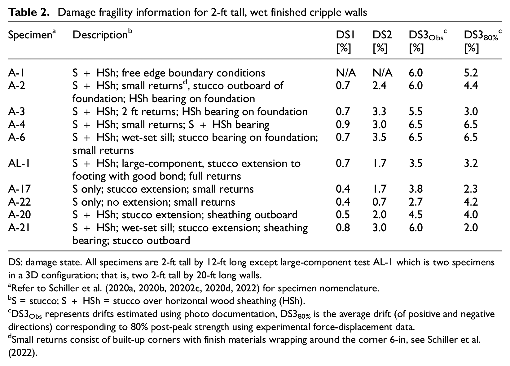
DS: damage state. All specimens are 2-ft tall by 12-ft long except large-component test AL-1 which is two specimens in a 3D configuration; that is, two 2-ft tall by 20-ft long walls.
Refer to Schiller et al. (2020a, 2020b, 20202c, 2020d, 2022) for specimen nomenclature.
S = stucco; S + HSh = stucco over horizontal wood sheathing (HSh).
DS3Obs represents drifts estimated using photo documentation, DS380% is the average drift (of positive and negative directions) corresponding to 80% post-peak strength using experimental force-displacement data.
Small returns consist of built-up corners with finish materials wrapping around the corner 6-in, see Schiller et al. (2022).
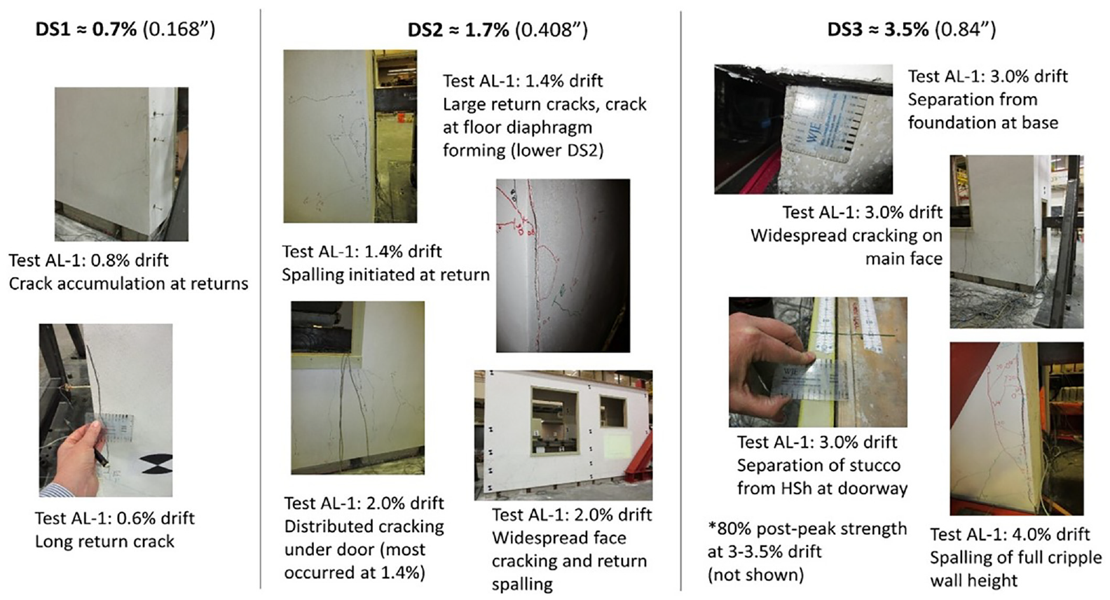
Photographs from Specimen AL-1 used to estimate drift amplitudes associated with stucco damage states.
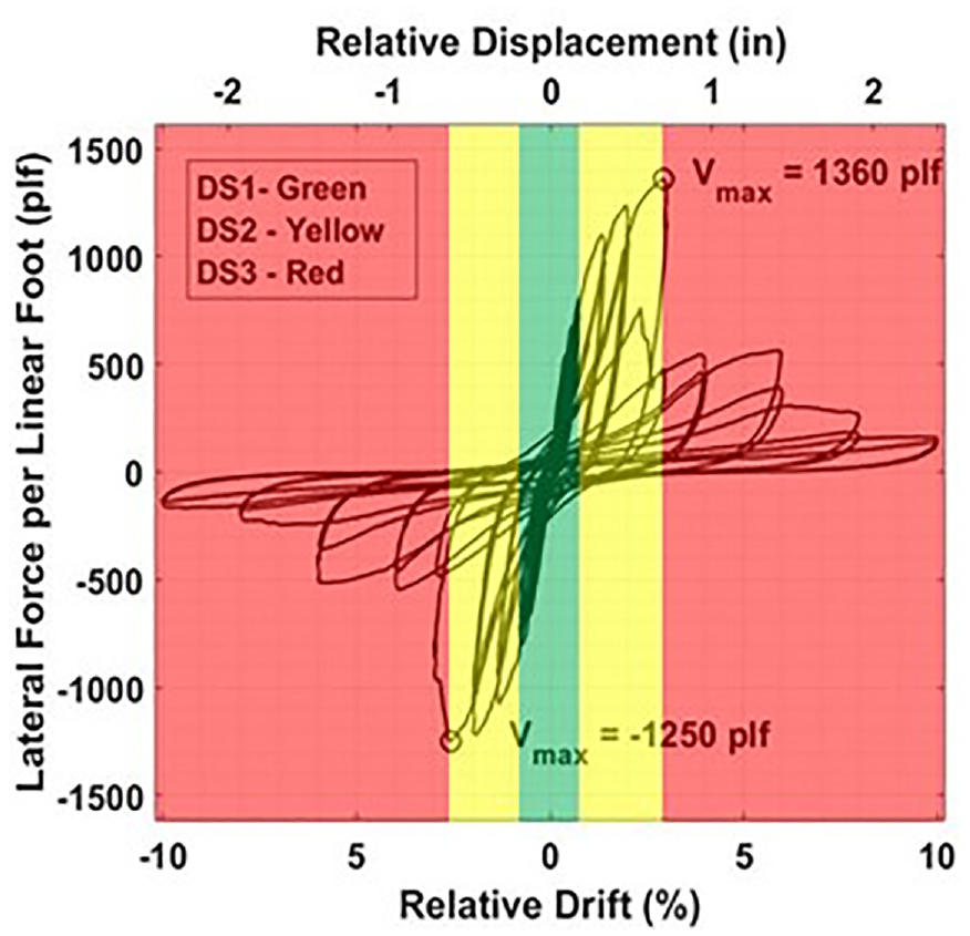
Damage states overlaid on the lateral strength—relative displacement hysteretic response of Specimen AL-1.
On the exterior of the stucco finished cripple walls, visible damage was similar regardless of the presence of sheathing. In both cases, the displacement imposed on the cripple walls induced stresses throughout the stucco, leading to visible damage of the specimens. At low-displacement amplitudes, small vertical and diagonal cracks propagated at the ends of the cripple walls. Along the face of the specimens, some vertical cracks appeared; however, they were not present for all of the specimens tested. For all of the small-component tests, the finish material wrapping the corner was seated on the foundation. When displacement was imposed on the cripple walls, the bearing of the stucco on the foundation caused cracks to form at the corners, while there were few cracks that formed on the face of the specimens. For the stucco-only cripple walls, Damage State 1 (DS1) was reached by 0.4% drift while it was reached around 0.7% drift for the stucco over horizontal sheathing specimens. Once the cripple walls had reached peak strength, the stucco had detached from the furring nails connected to the framing and sheathing material. This produced a gap at the bottom of the cripple walls and led to a significant drop in capacity in subsequent displacement cycles. Visibly, it appeared that the stucco finish was flaring out from the sill plate. By this point, many vertical cracks had formed at the corners on the face of the specimens. In addition, it was common to see spalling and heavy cracking of the stucco at the corners which were bearing on the foundation. The damage to the cripple walls at this point is defined as Damage State 2 (DS2). For the stucco-only cripple walls, this occurred between 0.7% and 1.7% drift. DS2 was achieved between 1.7% and 3.5% drift for the stucco over diagonal sheathing cripple walls. Once strength had been reached, increases in imposed displacement caused the vertical cracks at the edge of the stucco face to propagate upward to the top plates. The width of the cracks at the corners extended, and the stucco had nearly completely delaminated from the framing and sheathing. From observation, the damage to the cripple walls would push the specimen to be in Damage State 3 (DS3). For the stucco-only cripple walls, this occurred between 2.7% and 3.8% drift. It occurred between 3.5% and 6.5% drift for the stucco over horizontal sheathing finished cripple walls. It should be noted that specimens AL-1 and A-20 which were constructed with the same details and boundary conditions had similar drifts at the damage states of interest, while other small-component specimens with stucco over horizontal sheathing finished cripple walls with variations in their boundary conditions did not (see Schiller et al., 2022 for additional comparison of large- and small-component specimen behavior).
DS3 may be alternatively characterized by identifying the drift and associated specimen state at 80% post-peak strength. From Table 2, it can be seen that there were significant differences in the drifts based on the two different criteria. In nearly all cases, the observed DS3 occurred at drift amplitudes larger than the DS3 identified using 80% post-peak drift. This indicates that the definition of 80% post-peak strength as a trigger for DS3 may not amply define widespread connection failure, and a larger drift capacity associated with DS3 is plausible.
For stucco over diagonal sheathing finished specimens, damage trends were similar to other wet finished specimens at early drift amplitudes. Due to the strength and orientation of the diagonal sheathing boards, all cripple wall finished with stucco over diagonal sheathing failed due to fracturing of the anchor bolts and cross-grain splitting of the sill plate. The cross-grain sill plate cracking was primarily a result of the diagonal sheathing board displacing upward which caused large stresses to develop in the sill plate where it was attached. Failure of the sill plate and anchor bolts caused subsequent displacement cycles to produce a decrease in relative drift of the cripple wall due to most of the imposed displacement being accumulated between the sill plate and the foundation. These failures also prevented the cripple wall from reaching their full capacity had the sill plate and anchor bolts stayed intact. Figure 5 shows these failures for the Specimen A-15, which was constructed in its existing condition, that is, sans retrofit.
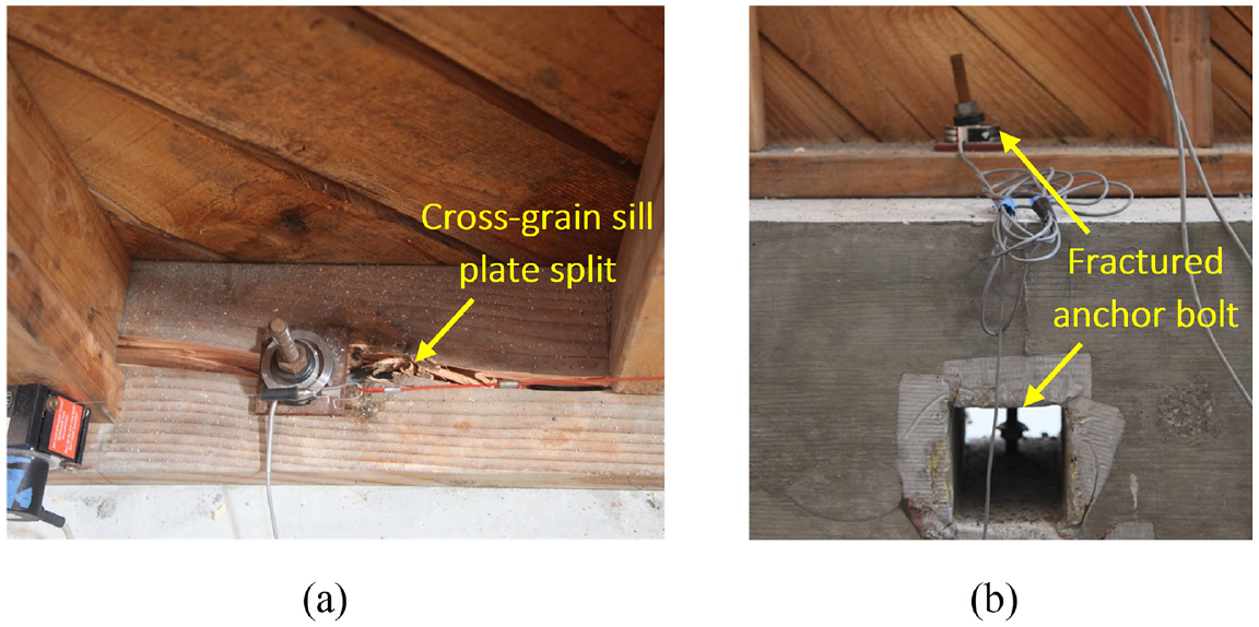
Photographs of damage for Specimen A-15. (a) Cross-grain sill plate splitting. (b) Fracturing of anchor bolt.
In Figure 6, damage from small-component specimen A-25, which is an existing, 6-ft tall cripple wall finished with stucco over framing is shown with the drift values for each damage state. By comparing the drift values for the 6-ft-tall specimen with those of the 2-ft-tall cripple walls finished with stucco over framing, it can be seen that the increased height of the cripple wall caused the damage states to be reached at smaller drift amplitudes. The reduced drift for the damage states of the 6-ft-tall specimen is attributed to the imposed displacement being three times that of the 2-ft-tall specimen for each drift target. Due to the rigidity of the stucco and its continuity across the entire height of the cripple wall, damage was observed at smaller drift amplitudes because of the increased displacement imposed for the taller specimen.
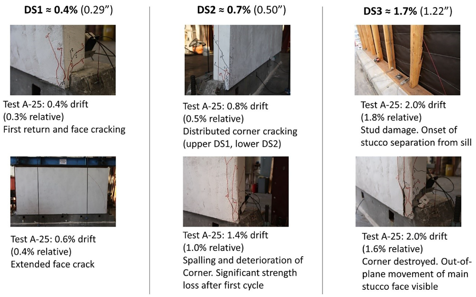
Photographs from Specimen A-25 used to estimate drift associated with stucco damage states for a 6-ft-tall cripple wall.
Dry finished specimens
In total, 11 dry (or non-stucco) finished specimens were tested in the small-component program. Five of these specimens were in the retrofit condition and six were in the existing condition. There were four specimens finished with horizontal ship-lapped siding, four finished with T1-11 wood structural panels, and three finished with horizontal ship-lapped siding over diagonal sheathing. Two of the horizontal siding finished specimens and two of the T1-11 finished specimens were 6-ft tall, and all other specimens were 2-ft tall.
Unlike the wet finished cripple wall, each of these types of dry finished cripple walls have different damage states associated with them. During the early displacement cycles of testing, horizontal siding cripple walls showed little visible damage. Due to this and the limited availability of experimental data, the horizontal siding finished cripple walls only have one damage state which would warrant replacement of the cripple wall. The three small-component tests with horizontal siding over diagonal sheathing showed that there is little visible damage to the exterior of the specimens, while there is significant damage to the interior of the specimens. Because of this, like the horizontal siding finished specimens, there is only one damage state for the horizontal siding over diagonal sheathing cripple walls which warrants replacement of the cripple wall. The last dry exterior finish tested, T1-11 wood structural panels have little experimental data outside of the tests performed within the present small-component program; however, there is ample data on tests performed with wood structural paneling, such as oriented strand board (OSB) and plywood. Since T1-11 panels are wood structural panels similar to OSB and plywood, the same damage states and descriptions are adopted. The damage states for T1-11 wood structural panel finished cripple walls are described in Table 3 and were derived from Welch and Deierlein (2020).
Damage and repair descriptions for T1-11 wood structural panel finished cripple walls
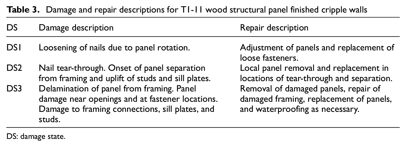
DS: damage state.
Testing of small components showed that horizontal siding finished cripple walls had low strength and stiffness compared with other finish materials, yet also a high drift capacity. The 2-ft-tall specimen reached only 30% of the lateral strength of the next weakest 2-ft-tall specimen, and the 6-ft-tall specimen only reached 25% of the lateral strength of the next weakest 6-ft-tall specimen. Due to the flexible nature of horizontal siding finishes, over the entire loading protocol, the 2-ft-tall specimen only had around a 40% reduction in peak strength, and the 6-ft-tall specimen experienced less than a 10% reduction in peak strength. The large drift capacity of the horizontal siding finished cripple walls was also exhibited by the minimal amount of observable damage to the specimens. As the displacement amplitude increased, the siding boards displaced relative to each other. At large displacement amplitudes, there was a small amount of pullout of some of the fasteners attaching the siding to the framing. From the interior, the building paper was heavily torn, and the studs were rotated but undamaged, see Figure 7.
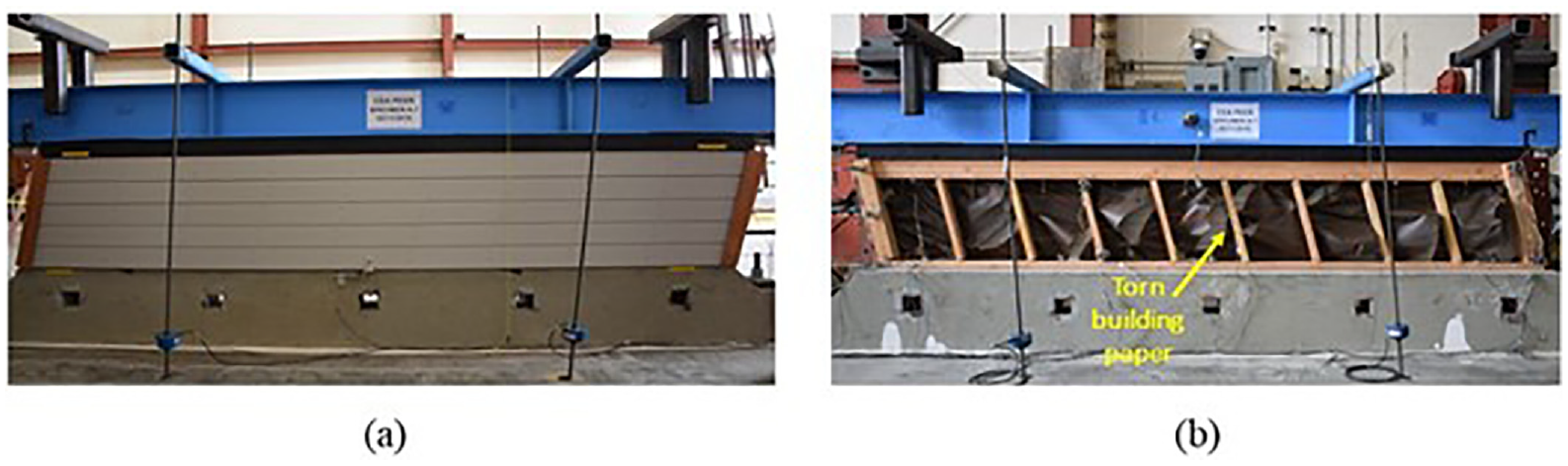
Damage observations from existing cripple walls finished with horizontal siding. (a) Exterior face of 2-ft-tall specimen. (b) Interior face of 2-ft-tall specimen.
For cripple walls finished with horizontal siding over diagonal sheathing, there was more observable damage in the variety of elements of the specimen. Figure 8 shows damage observed for cripple walls finished with horizontal siding over diagonal sheathing. Similar to specimens finished with stucco over diagonal sheathing, these specimens failed as a result of anchor bolt fractures and cross-grain splitting of the sill plate. Along the interior, there was significant cracking of the sheathing boards along with cracking of the sill plate and fracturing of the anchor bolts (Figure 8a and b). The existing cripple wall with horizontal siding over diagonal sheathing was the only small-component test configuration to be tested with a light (Specimen A-28) and heavy axial load (Specimen A-9). With the decrease in axial load, large amount of uplift of the specimen occurred. This uplift resulted in the most severe cross-grain splitting of the sill plate observed, as shown in Figure 8b.
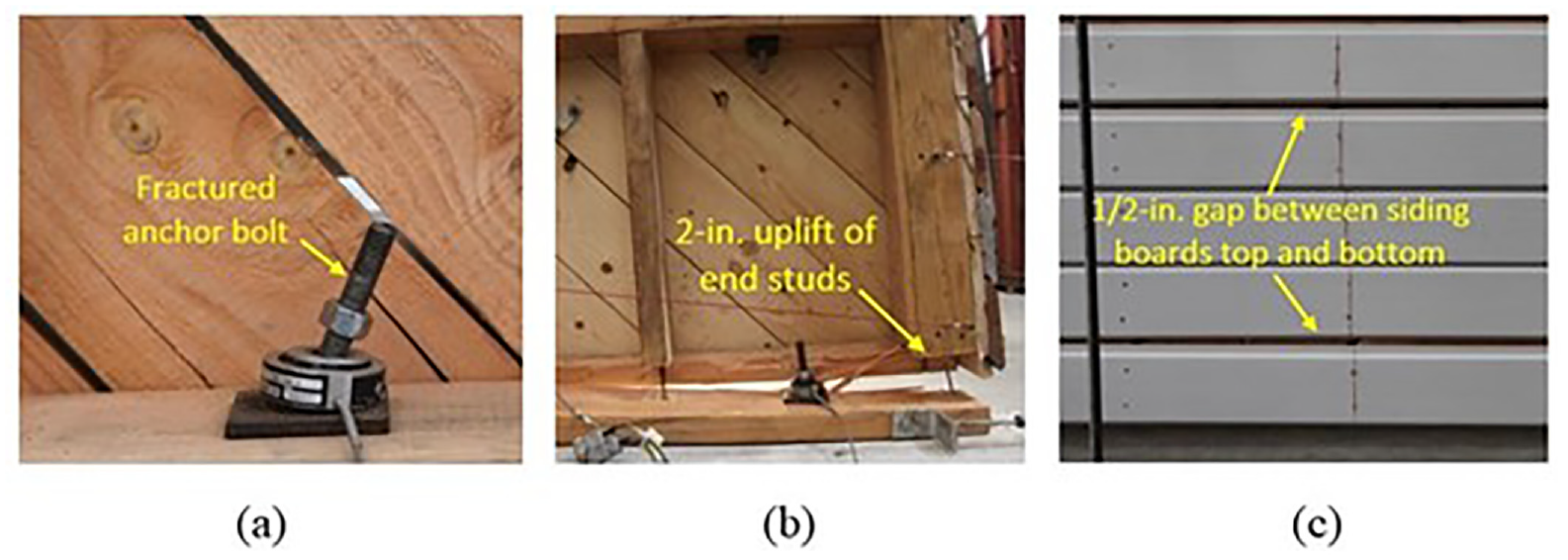
Damage observations from existing cripple walls finished with horizontal siding over diagonal sheathing. (a) Uplift of cripple wall from Specimen A-28. (b) Anchor bolt fracture of Specimen A-9. (c) Damage to exterior face for Specimen A-9.
The final dry finished specimen tested was constructed with T1-11 wood structural panels. Unlike the other two types of dry exterior finished cripple walls, there was a much more discernable evolution of damage observable from the exterior of the T1-11 specimens. Each of the three damage states defined for the T1-11 specimens was easily observable for both the 2-ft-tall cripple wall (Specimen A-11) and the 6-ft-tall cripple wall (Specimen A-23). Figure 9 shows photographs used to estimate the drift that meet the criteria of each damage state for the 2-ft-tall cripple walls, and Figure 10 shows the same for 6-ft-tall cripple walls. DS1 is described as loosening of the panel-to-framing fasteners. For the 2-ft-tall specimen, this was observed around 2.5% drift, and for the 6-ft-tall specimen, it was visible around 1.1% drift. DS2 constitutes tear-through of the panel-to-framing fasteners. Both tear-through and pullout of these fasteners were observed for both specimens. For the 2-ft-tall specimen, the estimated drift for DS2 was at 5.0%, while it was 2.5% for the 6-ft-tall specimen. Nail tear-through and pullout signified that the cripple wall was either at peak strength or the strength had begun to degrade. Finally, DS3 entails detachment of the T1-11 panel from the framing. This would occur when a significant portion of the panel-to-framing fasteners had torn through the panels or pulled out of the framing. For the 2-ft-tall specimen, this occurred around 6% drift, and for the 6-ft-tall specimen, it occurred around 4% drift. It should be noted that the relationship between estimated drift to reach each damage state for the two heights of cripple walls was in reasonable agreement with the stucco over framing finished cripple walls.
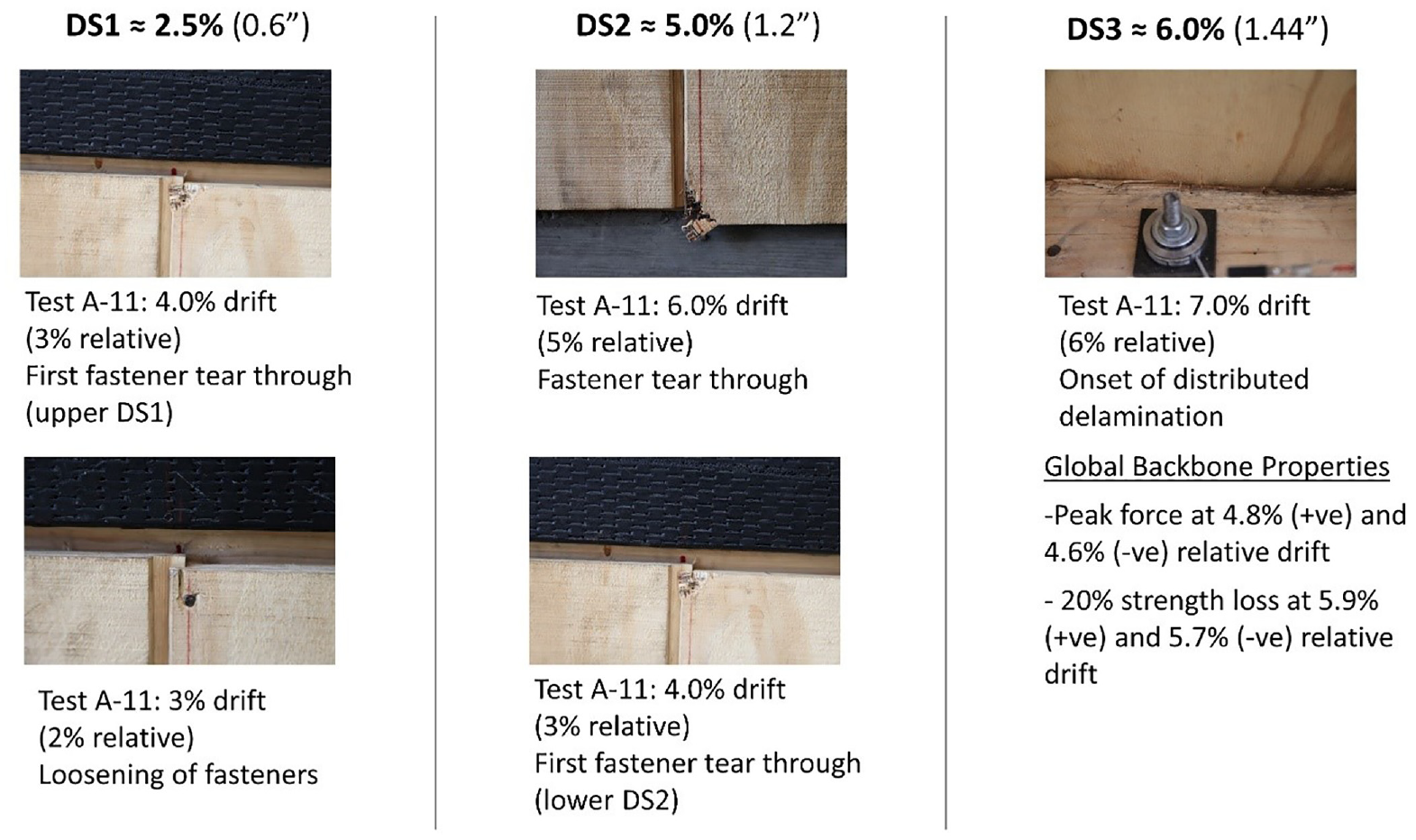
Damage states for the 2-ft-tall, unretrofitted T1-11 cripple wall (Specimen A-11).
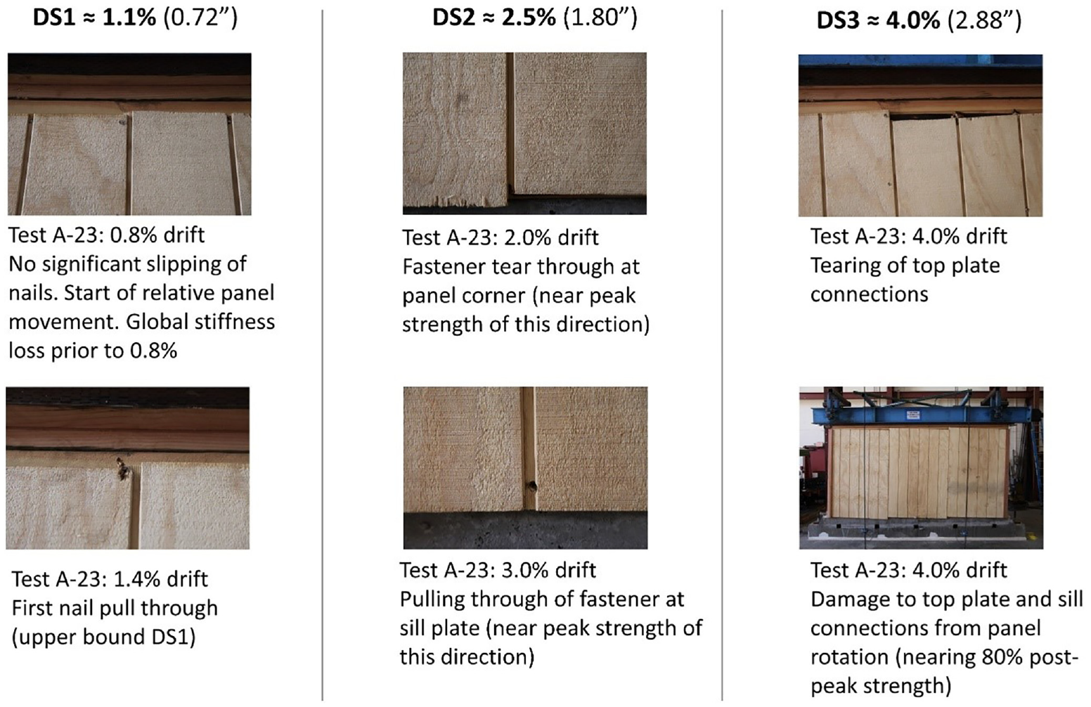
Damage states for the 6-ft-tall, unretrofitted T1-11 cripple wall (Specimen A-23).
FEMA P-1100 retrofitted specimens
As stated previously, with the exception of T1-11 finished walls, the FEMA P-1100 prescriptive retrofit involves adding wood structural panels to the interior of the cripple wall. For T1-11 specimens, retrofit involves the addition of supplemental nailing on the exterior panel face. It is noted that, on the addition of interior wood structural panels, damage is both concentrated on the cripple wall exterior face and the interior structural panels. Both experimental programs confirm that the FEMA P-1100 retrofit increased the strength and stiffness, and in many cases, the drift capacity of the specimens was tested. For wet finished specimens, damage to the stucco occurred at drift amplitudes similar to those of the unretrofitted specimens. Although, at these drift amplitudes, there was no loss in load capacity of the cripple wall due to the retrofit elements continuing to provide increases in strength despite the detachment of the stucco furring nails at the sill plate and bottom of studs. When this detachment occurred, there was visible rotation of plywood panels and rotation of the fasteners attaching the panels to the framing. With increasing imposed displacement, physical damage accrued at the added retrofit locations, and these locations led to the loss of capacity of the cripple walls. Therefore, the evolution of damage to these components resulting in loss of capacity is primarily visible from the interior face of the crawlspace area. Damage to retrofitted cripple walls was fairly consistent regardless of the exterior finish material or height of the specimen. Following damage to the interior retrofit components, visible damage to the exterior of the cripple walls was consistent for both existing and retrofitted cripple walls. Common damage features of the retrofit components that led to a loss of capacity were crushing of the panels where the panels were bearing on flat studs at corners, pullout and tear-through of the nailing, splitting of the blocking attached to the sill plate, splitting and movement of the studs, and plywood delamination. For dry finished specimens, while the drift capacity of the retrofitted specimen increased, the damage features that matched the criteria for reaching a damage state were similar regardless of the retrofit condition. However, for the specimens with stucco exteriors, visual cues leading to an estimated drift to define a damage state did not have a strong correlation to the capacity of specimens. The imposed displacement would cause a comparable level of damage to the stucco finish, but the capacity would continue to increase with increased displacement amplitude due to the retrofit components still remaining intact. In Figure 11, damage from small-component specimen, A-26, which is a retrofitted, 6-ft-tall cripple wall finished with stucco over framing, is shown with the drift associated with each damage state.
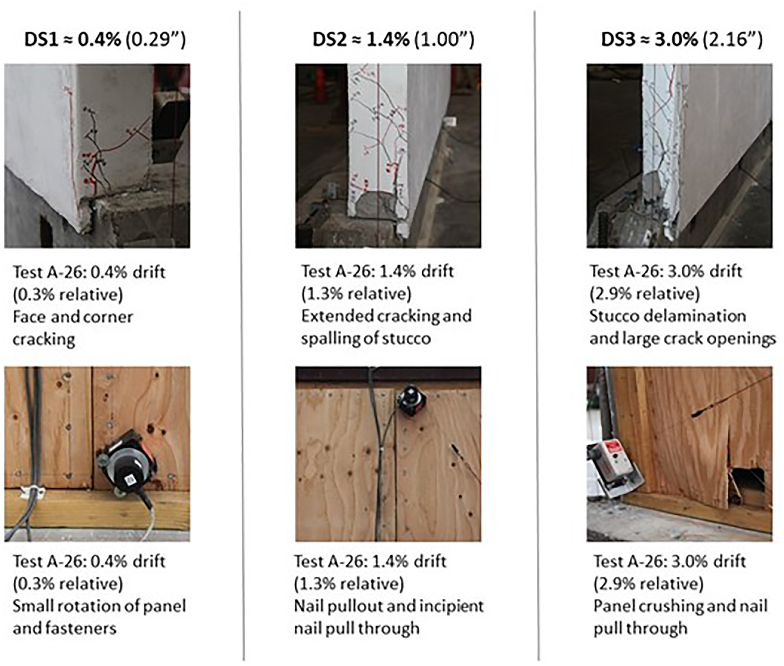
Damage states for the 6-ft-tall, retrofitted stucco over framing cripple wall (Specimen A-26).
For the retrofitted T1-11 finished cripple wall, there were comparable drift values for each damage state with their existing (non-retrofitted) counterparts. Unlike all other cripple walls, those finished with T1-11 were not retrofitted through plywood being added to the interior of the studs. Instead, additional nails were added to reduce the nail spacing from 8-in on center to 4-in on center, and an additional row of nails added at overlapping panels. With the additional nailing, the cripple walls were able to reach larger drift amplitudes before reaching each damage state.
Development of damage fragilities for cripple walls
Damage fragilities derived for this project take the form of cumulative lognormal distributions defined by a median and dispersion value. Details on fragility development as adopted in this work can be found in Appendix H of FEMA P-58-1 (FEMA, 2012b). This sub-section highlights the main findings of the damage fragility development for cripple-wall sub-assemblies, where more in-depth information on damage fragilities used for FEMA P-58 analysis within the PEER-CEA Project can be found in Welch and Deierlein (2020).
The main finding of the damage fragility study was that continuous (stucco) and panelized (T1-11 siding) cripple wall materials do not exhibit consistent damage thresholds defined in terms of story drift ratio (SDR; e.g. story displacement divided by story height) at different wall heights. This is counter to horizontal wood-siding cripple walls, which do not have significant height dependence. These cripple walls do not have panels extending the full height of the cripple wall as do those with stucco and T1-11 exterior finishes. During testing, individual siding boards displace equally relative to each other, meaning that there are no considerable differences in the deformation of fasteners on one siding board versus another, regardless of wall height. The difference of material drift compatibilities with varying height is illustrated in Figure 12. A key impact of the height dependence is that damage estimates could be significantly overestimated if fragilities based on full-height (e.g. 8-ft tall) walls are applied to shorter cripple walls using drift as the engineering demand parameter. The height dependence for stucco walls (Figure 12a) in terms of SDR is articulated by assuming a 1-in global displacement of the walls. With similar demands on the lower stucco connections (since the stucco wants to move as a single unit), the corresponding SDR demands are 1.0% and 0.4% for the 8- and 2-ft walls, respectively.
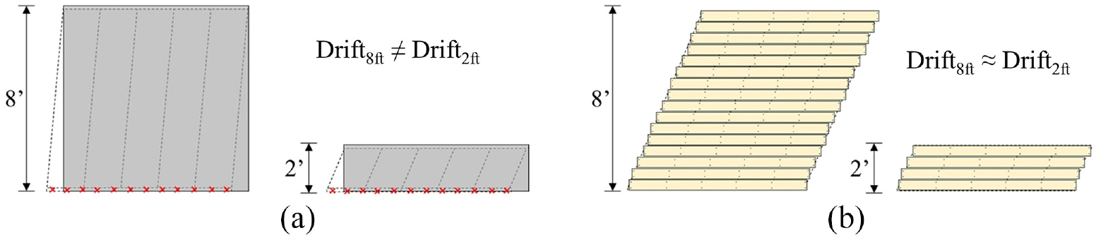
Illustration of wall materials having different drift compatibilities with varying height. (a) No drift compatibility (stucco, T1-11). (b) With drift compatibility (horizontal wood siding). Note that drift refers to the SDR of the walls taken as lateral displacement divided by height.
The difference is stucco damage fragility functions expressed in terms of SDR are compared in Figure 13 for 8- and 2-ft wall heights. The fragilities are based on the observations from experimental data (Welch and Deierlein, 2020) and do not include additional uncertainty adjustments recommended by Appendix H of FEMA P-58 (FEMA, 2012b). The figure shows the drastic difference in damage progression in terms of SDR (i.e. lateral displacement divided by wall height).
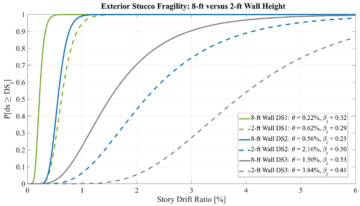
Comparison of 8- and 2-ft stucco fragility functions fit to observations from raw experimental data. Dispersion values do not include additional uncertainty adjustment and reflect specimen-to-specimen uncertainty only.
Following review of experimental data, a variation of the height adjustment relationship used within the FEMA P-807 guidelines (FEMA, 2012a) to relate difference in peak strength of shorter bottom story walls to full-height walls was proposed to capture the difference in median damage state drift for shorter cripple walls. For cripple wall materials, other than horizontal wood siding, median SDR values for full-height fragility curves are scaled by the height-dependent relationship as shown in Equation (1):
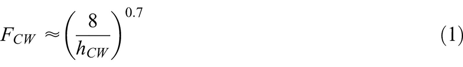
where FCW is the cripple wall fragility factor and hCW is the height of the cripple wall expressed in feet. An example of implementing Equation (1) to exterior stucco for 6- and 2-ft-tall cripple walls is shown in Table 4 in comparison to the full-height stucco fragility developed for older full-height walls (e.g. without panelized sheathing) by Welch and Deierlein (2020). Figure 14 compares the proposed height adjustment (solid lines) to fragility functions fit to experimental data (dashed lines) for 2-ft stucco cripple walls, see Table 4 for data. Figure 14 shows that the relationship has very good agreement with DS1 (cracking) and DS3 (replacement), where DS3 is based on 80% post-peak strength. DS2 (stucco spalling) is slightly conservative with the proposed relationship and reflects the difficulty in estimating this damage state from photo documentation. This difficulty can be observed by comparing the DS3 curves in Figure 14 for “observed” and “80% post-peak” curves, where the latter provided median values larger than the former, on a similar magnitude as the lack of fit of the proposed DS2 curve to the observed DS2 curve. This highlights the possible differences in assessing damage through photo documentation at incremental drift demands versus the actual conditions that would require closer inspection, as would occur before performing actual repairs. Similar agreement was found for T1-11 siding cripple walls, yet with only rough comparisons possible due to the much more limited test data on T1-11 than stucco cripple walls. The consideration of cripple wall height proposed herein is rather simplistic and could be improved as more test data become available. However, this consideration can be viewed as a considerable improvement over applying story drift-based fragility functions for full-height walls to shorter cripple walls. More details on the comparisons of the proposed height relationship and fragility development can be found in Welch and Deierlein (2020).
Stucco damage fragility functions for cripple walls using a height-dependent scaling relationship from full-height stucco fragilities
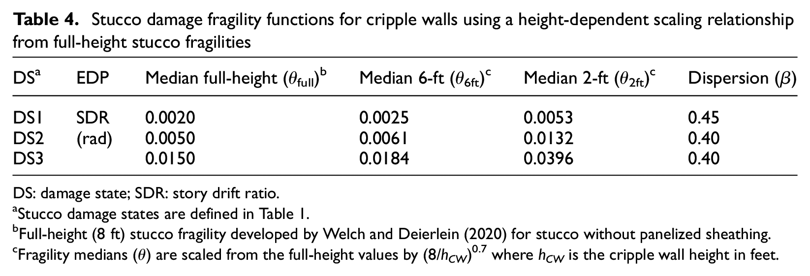
DS: damage state; SDR: story drift ratio.
Stucco damage states are defined in Table 1.
Full-height (8 ft) stucco fragility developed by Welch and Deierlein (2020) for stucco without panelized sheathing.
Fragility medians (θ) are scaled from the full-height values by (8/hCW)0.7 where hCW is the cripple wall height in feet.
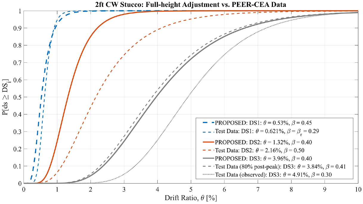
Comparison of the 2-ft-tall stucco cripple-wall fragilities using the proposed height adjustment factor (solid lines) with data collected from PEER–CEA testing (dashed lines). Parameters θ and β are the median and dispersion values of a lognormal distribution, respectively.
Conclusions
This article summarizes the observations of damage and corresponding drift response levels for simulated seismic experiments conducted on cripple walls both with and without seismic retrofit conducted as part of the PEER–CEA Project. Cripple wall specimens tested were finished with two broad categories of exterior finishes, namely wet (stucco) and dry (non-stucco) finishes. Data from these experiments are used as a basis for seismic fragility functions considering three damage states. The main conclusions from the work presented herein are as follows:
Wet (Stucco) Finished Specimens:
DS1, corresponding to minor cracking of the stucco, occurred by 0.7% relative drift for all wet finished specimens.
DS2, corresponding to spalling of the stucco and delamination of the stucco from the sheathing or studs, occurred between 0.7% and 1.7% relative drift for stucco finished cripple walls. For stucco over horizontal sheathing and stucco over diagonal sheathing finished cripple walls, the damage was restrained further, with the range of DS2 between 1.7% and 3.5% relative drift.
DS3, corresponding to stud fracturing, sill plate cracking, and near-complete delamination of the stucco, occurred between 2.7% and 3.8% relative drift for stucco finished cripple walls. For stucco over horizontal sheathing finished cripple walls, the range was 3.5%–6.5% relative drift.
Dry (Lumber) Finished Specimens:
For horizontal-siding finished specimens, there was little observable damage, even at large drift amplitudes, due to the highly flexible nature of these cripple walls.
For T1-11 finished specimens, DS1, corresponding to primarily loosening of nails and minor cosmetic damage, occurred by 2.5% relative drift. While DS2, physically presenting nail tear-through and panel separation, occurred by 5.0% relative drift, and DS3, corresponding to panel partial/full detachment, occurred at 6.0% relative drift.
FEMA P-1100 Retrofitted Cripple Walls:
For wet finished, retrofitted specimens, the observable damage characteristics correlating the three damage states occurred at similar drift amplitudes as the existing specimens; however, the strength continued to increase at larger drift amplitudes due to the addition of the retrofit components.
For T1-11 finished specimens, DS1 was attained at the same drift amplitude regardless of the retrofit condition. However, subsequent damage states were attained at larger drift amplitudes due to the additional nailing along the panels.
Height Dependence of Cripple Walls:
Unlike horizontal-siding finished cripple walls, stucco and T1-11 finished cripple walls did not exhibit consistent damage thresholds, defined in terms of story drift, with varying wall heights. A proposed scaling for cripple wall fragility curves based on full-height fragility curves is provided in this work.
Footnotes
Declaration of conflicting interests
The author(s) declared no potential conflicts of interest with respect to the research, authorship, and/or publication of this article.
Funding
The author(s) disclosed receipt of the following financial support for the research, authorship, and/or publication of this article: This research study was funded by the California Earthquake Authority (CEA). The support of the CEA is gratefully acknowledged. The authors appreciate the continued input and support of the CEA and all members of the Pacific Earthquake Engineering Research Center (PEER)–CEA project team. The opinions, findings, conclusions, and recommendations expressed in this publication are those of the authors and do not necessarily reflect the views of the CEA, PEER, project team members, or the Regents of the University of California.