
Abstract
As part of the Pacific Earthquake Engineering Research Center (PEER)-California Earthquake Authority (CEA) project, experimental programs were performed at UC San Diego and UC Berkeley, with the former focusing on small-component testing and the latter focusing on large-component testing. During the small-component testing program, a suite of 28 cripple wall-only specimens was tested under quasi-static reverse cyclic lateral loading with variations in exterior finishes, retrofit condition, cripple wall height, anchorage condition, boundary conditions, vertical load, and loading protocol. In the large-component testing program, cripple wall-first story specimens, load path connections, and combined materials in occupied stories were tested. The more easily performed small-component specimens facilitate comparison with the large-component specimens to allow the assessment of their potential to emulate large-scale specimen behavior, with a particular interest in cross-comparing their global hysteresis and physical damage evolution. This cross-comparison among small- and large-scale specimen test results is intended to offer best practices for the future design of cripple wall seismic retrofits in residential housing, with a particular interest in: (1) supporting the realistic design of small-component specimens that may capture the response of large-component specimens and (2) to qualitatively determine where the small-component tests fall in the range of lower- to upper-bound estimation of strength and deformation capacity for the purposes of numerical modeling. Data from both test programs were utilized in the PEER-CEA project to assist with validating numerical modeling tools, which in turn were used to generate seismic loss models capable of quantifying the reduction of loss achieved by applying state-of-practice retrofit methods as identified in FEMA P-1100 Vulnerability-Base Seismic Assessment and Retrofit of One- and Two-Family Dwellings. The objective of this article is to present an overview of the small- and large-component testing programs and key results pertaining to exterior finishes, boundary conditions, the FEMA P-1100 retrofit, and cripple wall height.
Introduction
Physical experimentation offers important control data to assist with advancing numerical modeling tools. Such data have been pursued using a range of test specimen geometries and scales. In the wood testing arena, smaller-scaled specimens are useful due to their economy of scale and simplicity, allowing a number of tests to be conducted efficiently. At odds with efficient modest scale, experimentation is the desire to realistically capture load path continuity at boundaries with larger-scaled specimens that include both the primary component of interest as well as select adjacent elements of the subsystem. To advance understanding of wood cripple wall seismic performance, smaller-scaled, single-component specimens have been of sole focus in prior experimental programs.
Among the largest test programs conducted to date, under the auspices of the CUREE-Caltech research program, UC Davis conducted 15 tests on stepped cripple walls and 13 tests on level cripple walls, all 12 ft in length (Chai et al., 2002). Variables in this testing program included cripple wall height (2 and 4 ft tall), use of stucco exterior finish, vertical load (100 and 450 plf), percent bracing of 15/32-in. OSB (66% and 100%), and loading history (monotonic push, ordinary ground motion, and near-fault ground motion). In addition, for stepped cripple walls, two slopes of stepped cripple walls were used, 1-in-2 slopes and 1-in-3 slopes. The loading protocol was a deformation-controlled, quasi-static cyclic protocol representing near-fault and ordinary ground motions. While this testing program provided valuable information on the seismic response of cripple walls, it was limited by the boundary conditions and exterior finish styles used in the construction of the cripple walls as well as being conducted prior to current retrofit prescriptions.
At the start of 2013, the Federal Emergency Management Agency (FEMA), the Applied Technology Council (ATC), and the California Earthquake Authority (CEA) jointly funded a project to develop a prestandard for seismic retrofit of single-family wood light-frame dwellings (Blaney et al., 2018). Findings from this project were published as FEMA P-1100: Vulnerability-Based Seismic Assessment and Retrofit of One- and Two-Family Dwellings (Federal Emergency Management Agency (FEMA), 2018). This retrofit methodology consists of adding wood structural panels to cripple walls, anchor bolts to sill plate–foundation interfaces, and shear clips to cripple wall-first story interfaces, to properly brace cripple walls and transfer lateral loads to the foundation. Despite the availability of this prestandard, an experimental basis for the new detailing prescriptions was limited.
To address prioritized gaps in data regarding the seismic performance of wood cripple walls and the aforementioned paucity of data supporting recent retrofit guidelines, within the Pacific Earthquake Engineering Research Center (PEER)-CEA project, an experimental program was executed at the University of California, Berkeley (UC Berkeley) and the University of California, San Diego (UC San Diego). UC San Diego’s program consisted of testing only cripple-wall assemblies, herein denoted as the small-component testing program (Schiller et al., 2020a, 2020b, 2020c, 2020d), while UC Berkeley’s program consisted of testing cripple wall and first-story assemblies, denoted herein as the large-component testing program (Cobeen et al., 2020). In this article, an overview of both experimental programs, including their test setups, variables, and loading protocols, is presented. Following this, key results, namely, the strength and deformation capacity, of the small-component specimens are provided. In addition, a comparison between the cripple wall-only specimens’ response from the small-component testing program and the cripple wall-first story assemblies of the large-component testing program is subsequently discussed. These comparisons are aimed at qualitatively evaluating where the small-component tests fall in the range of lower- to upper-bound estimation of strength and deformation capacity, while also facilitating advancements in numerical modeling. Finally, a summary of key damage observations obtained from the two testing programs is presented.
Experimental program overview
As part of the small-component program, a total of 28 cripple wall-only assembly tests were performed. Within the large-component program, two tests were performed on cripple wall-first-story assemblies, focusing on variation in the retrofit condition. In addition, the large-component program also included tests on occupied stories and load path connections. For both programs, the variables tested were determined based on representative “Index Buildings” and the variants within them (Reis, 2020). The variants to be tested were identified as: (1) parameters that would have a significant effect on the seismic response of the building, (2) parameters that have a statistically significant presence in California’s housing stock, and (3) the amount of damage reduction possible should the cripple wall be retrofit.
Upon identifying an experimental variant, it was noted that the selected variable must be observable to be quantified with fragility and damage functions (Reis, 2020). To this end, for the 28-cripple wall-only assemblies tested, the variables identified were: cripple wall exterior finish materials, retrofit condition, cripple wall height, boundary conditions, anchorage condition, loading protocol, and vertical loading. Both wet (stucco) and dry (nonstucco) exterior finishes were tested. The wet exterior finishes included stucco over framing, stucco over horizontal lumber sheathing, and stucco over diagonal lumber sheathing, while the dry exterior finished included horizontal ship lap lumber siding over framing, horizontal shiplap lumber siding over diagonal lumber sheathing, and T1-11 wood structural panels. These are the most common exterior finishes in California’s housing stock. It is important to note that nearly all finishes considered in the present program were lacking prior experimental data, with the exception of stucco exterior finished cripple walls, which were tested to a limited extent within the CUREE-CalTech program (Chai et al., 2002). Two cripple wall heights were considered, namely, 2 and 6 ft tall. These heights represent the lower and upper bounds commonly used in California dwellings, hypothesized to have a significant effect on the dominant lateral behavior of the cripple wall. While cripple walls are constructed at heights less than 2 ft tall, and may also be direct fastened (i.e. zero-height walls), such low heights approach pure shear-dominated, and thus in the present program deemed of lower priority, as their failure may be dictated by fastener failure.
Light and heavy axial loads were considered in these tests, namely imposed as a uniform load of 150 plf, representing a lower bound, that is, a one-story dwelling constructed with light building materials, and 450 plf, representing an upper bound, that is, a two-story dwelling constructed with heavy building materials. Axial loads were applied with either hydraulic jacks generating two-point loads along a rigid steel beam or weights from stacked plates positioned uniformly along the top of the cripple wall for the small component tests and along the top of the first floor and roof for the large component tests. The two types of anchorage used were typical sill bolt anchorage attaching the sill plate to the foundation and wet set sill plates, which consist of partially setting the sill plate into the foundation when it is cast. Wet set sill plates were commonly used in pre-1940 construction. The various boundary conditions used affect the top, bottom, and sides of the cripple walls (see Table 1). The baseline boundary conditions, denoted as top boundary condition B and bottom boundary condition c, positioned the cripple wall so that all exterior finishes were outboard of the foundation. In addition, the cripple walls with baseline boundary conditions had built-up corners with a 6-in. wraparound of the finish material. For wet finished specimens, top boundary condition B prescribed two rows of #11 (0.12 in. diameter) ×1 ½ in. furring nails spaced at 3 in. on the center along the two uppermost top plates (an additional top plate was used for a total of three top plates). This dense furring nail arrangement was formulated by Arnold et al. (2003) to simulate the strength contribution obtained from stucco being continuous across two floors. It is noted that this baseline boundary condition deviated from the most recent tests conducted within the CUREE-CalTech program, in an effort to more succinctly capture load path continuity of the first story of a dwelling (transitions from cripple wall to the first floor).
Summary of stucco over horizontal sheathing cripple wall specimens tested in the small component program
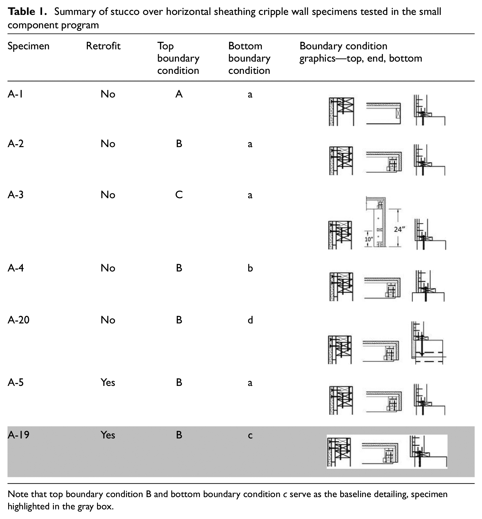
Note that top boundary condition B and bottom boundary condition c serve as the baseline detailing, specimen highlighted in the gray box.
Top boundary condition B was used as the baseline boundary condition as it provided a closer simulation of a dwelling’s cripple wall, including the built-up corners and furring nail arrangement to mimic continuity to the first-floor diaphragm. Top boundary condition C differed from top boundary condition B by its inclusion of 2 ft wall returns at each end (see Table 1). However, test results from specimens A-2 and A-3, which only differed under their top boundary condition showed that the out-of-plane wall returns had an insignificant effect on the in-plane response of the specimens. Since top boundary condition B was a cheaper and more easily constructed option, it was chosen for the baseline top boundary condition. As for the decision to use bottom boundary condition c as the baseline, it was chosen as it is the most commonly seen construction detailing in California’s housing stock (Reis, 2020). Each of the cripple walls was nominally 12 ft in length with small deviations depending on the top boundary condition used. Framing members were constructed with #2 Douglas Fir, with wall studs and top plates nominal 2 × 4 members and sill plates nominal 2 × 6 members. All studs were placed at 16-in on center. Studs were connected to the sill plate and top plate with 0.165-in.-diameter 2–16d common nails per stud. Additional top plates are connected with 16d common nails staggered at 16 in. on center. Figure 1a shows a test setup for a 2-ft-tall cripple wall prior to testing. The testing matrix for the small-component testing program is presented in Table 2.
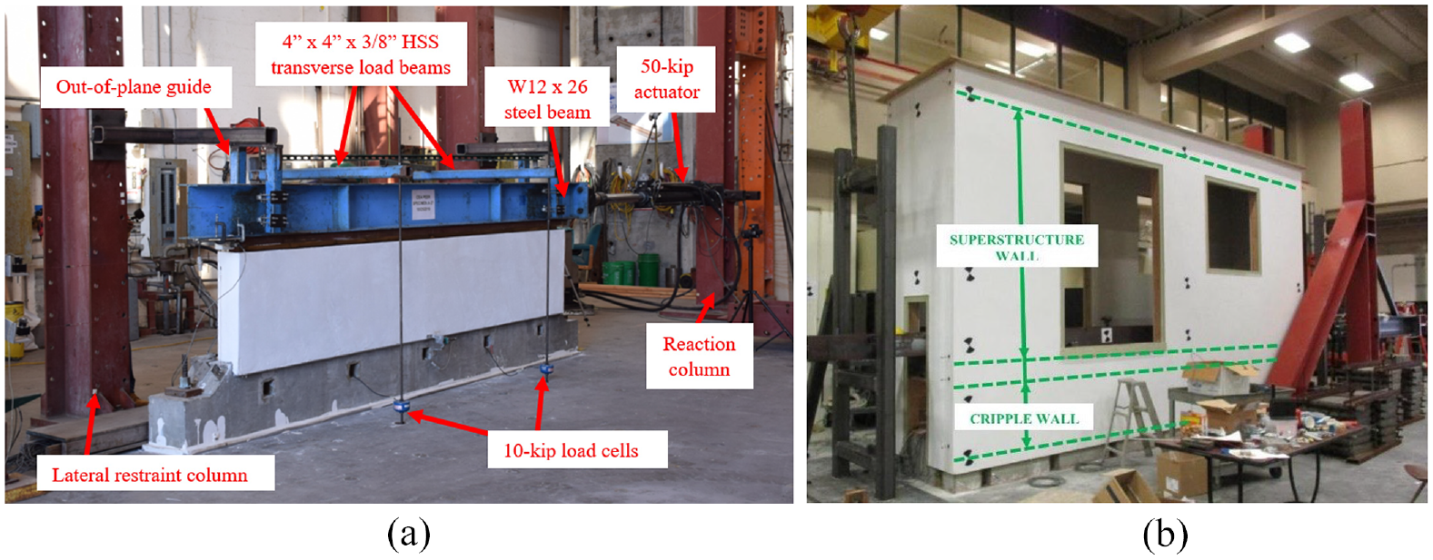
Test setup: (a) small-component cripple wall specimen and (b) large-component cripple wall- first story assembly.
Small-component test matrix
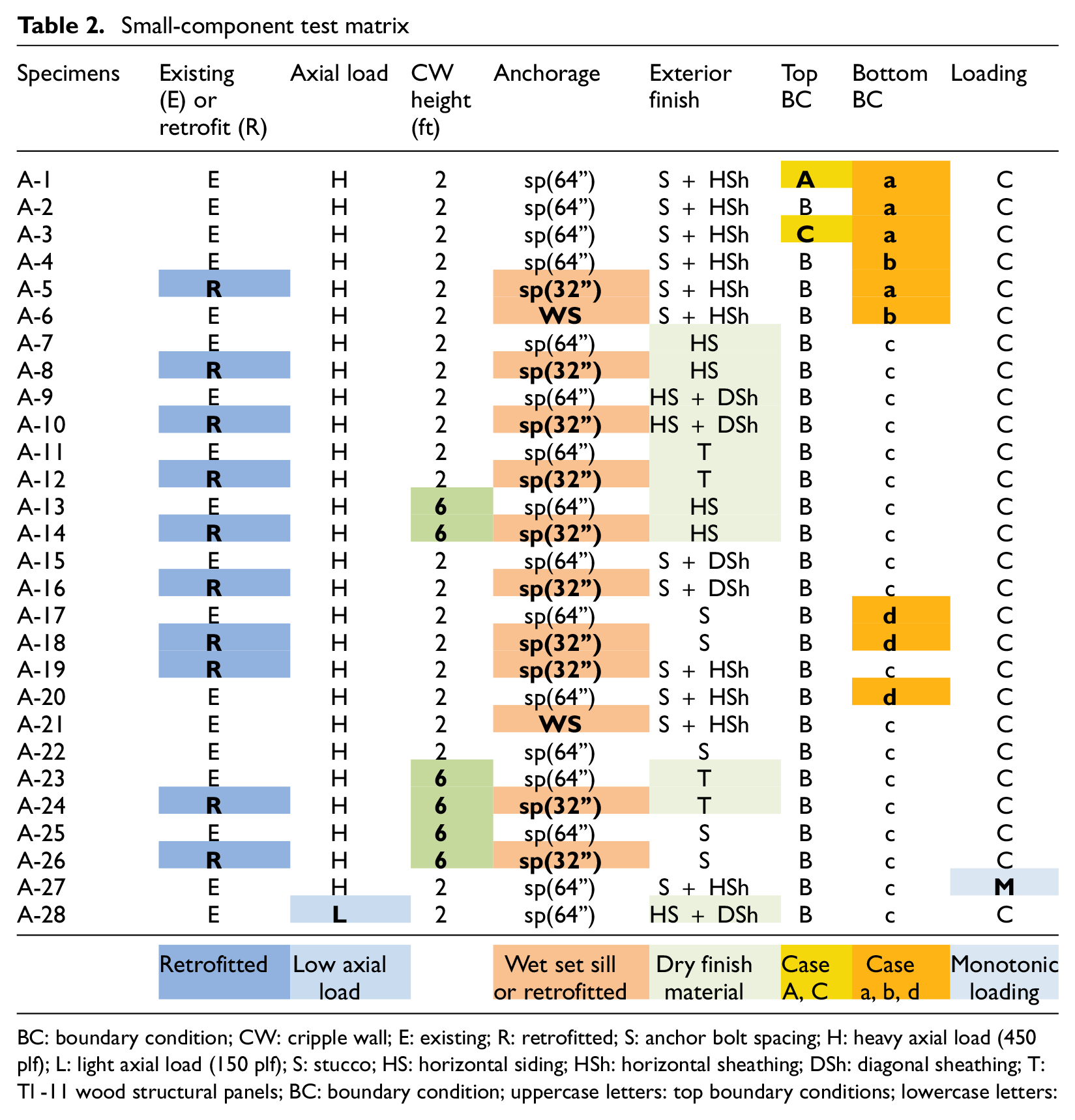
BC: boundary condition; CW: cripple wall; E: existing; R: retrofitted; S: anchor bolt spacing; H: heavy axial load (450 plf); L: light axial load (150 plf); S: stucco; HS: horizontal siding; HSh: horizontal sheathing; DSh: diagonal sheathing; T: Tl -11 wood structural panels; BC: boundary condition; uppercase letters: top boundary conditions; lowercase letters: bottom boundary condition; C: cyclic; M: monotonic; WS: wet set sill.
Testing of large component adopted similar criteria when considering variables of emphasis. Specifically, this program was divided into three groups, namely: cripple wall-first-story assemblies (Group A), load path connections (Group B), and combined materials in occupied story walls (Group C). The primary objective of Group A tests was to study the behavior of cripple walls with construction details and boundary conditions as close as possible to those occurring in representative dwellings for use as a basis to judge how closely the small-component tests replicate the response of the cripple wall in a complete dwelling. For Group B, the primary objective was to study the performance of commonly used retrofit load path connectors for which load deflection and performance information was not publicly available. Finally, for Group C, the primary purpose was to fill prominent gaps in testing information available for occupied story finish and sheathing materials commonly found in the California housing stock. Table 3 presents the testing matrix for Group A of the large-component testing program. The latter group B and C scope and results are not discussed herein and may be found in technical reports by the authors (Cobeen et al., 2020).
Large-component Group A test matrix
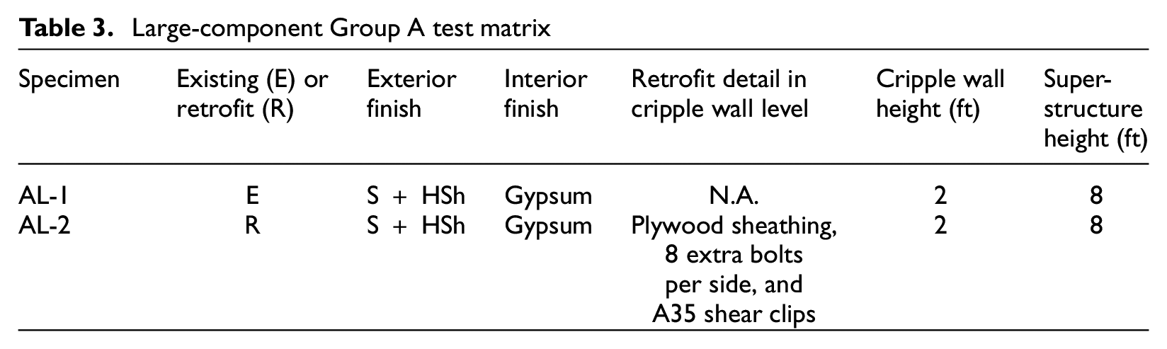
Within Group A, two tests were performed on cripple wall-first story assemblies, which were nominally identical with the exception that one was retrofit while the other was constructed in an as-built or existing (pre-retrofit) condition. The test assemblies were three-dimensional with a 20 ft × 4 ft footprint, which included the cripple wall and a single-story superstructure above and a foundation below. Specimens included a 2 ft-tall cripple wall seated on a concrete foundation, a framed floor, and 8 ft-tall superstructure walls, covered by a roof. A uniform gravity load of 450 plf along the cripple wall was imposed using lead weights placed on the roof. Each of these walls was chosen to have one door and one window, with the layout of each wall being a mirror image of the other. The test setup for Specimen AL-1 can be seen in Figure 1b.
Construction details of the cripple wall and first story were designed to be consistent with wall configurations seen in pre-1940 era California housing stock. Lateral loading to each specimen was imposed with a hydraulic actuator parallel to the 20 ft wall length. Specimens were referred to as AL-1 and AL-2, with AL-1 representative of an existing structure prior to retrofit and AL-2 representative of an existing structure with retrofit implemented. Both cripple walls were finished with stucco over horizontal lumber sheathing, which was the most common exterior finish in this era of construction. Both finish materials were seated outboard of the foundation. In addition, the stucco continued 8-in. down the face of the foundation whereas the sheathing terminated at the top of the foundation. This configuration is representative of bottom boundary condition d in the small-component testing program, thus small-component specimens A-20 and A-18 are most representative of AL-1 and AL-2, respectively.
For all wet finished specimens in the small-component testing program as well as specimens in the large-component testing Group A, the stucco was applied in accordance with the 1937 and 1943 editions of the Uniform Building Code (Pacific Coast Building Officials’ Conference 1937, 1943). This consisted of applying stucco in three layers, a 3/8-in. scratch coat, a 3/8-in. brown coat, and a 1/8-in. finish coat. Stucco was applied over wire lath, consisting of hexagonal shaped galvanized 1-1/2-in., 17-gauge wire mesh. The wire lath was attached to the framing using #11 (0.12-in diameter) ×1 ½ in. furring nails with 1/4 in. Furring nails were spaced at 6-in. on the center across the studs, sill plate, and floor joist. When sheathing was present, 1 × 6 construction grade Douglas Fir was used for all sheathing boards. Each board was fastened to the framing with 2–8d common nails per stud with 3-in. spacing between nails. Diagonal sheathing boards, when used for the small components, were fastened to the framing in the same manner, and the sheathing boards were orientated at a 45 degree angle. For small component cripple walls with horizontal siding, 1 × 6 shiplapped construction grade redwood was fastened to the sheathing and/or studs with the same nailing configuration as the sheathing boards. Cripple walls finished with T1-11 wood structural panels used 5/8-in. thick panels with 5/16-in thick grooves at 8-in. on the center. The panels were fastened with 8d common nails at 8-in. on the center. At the panel overlaps, only the overlaying panel was fastened, essentially sandwiching the underlying panel between the studs and overlaying panel.
Retrofit details
The prescriptive design provisions of the FEMA P-1100 pre-standard were the basis for implementing the retrofit condition on the cripple walls (FEMA 2018). In this case, design is based on the dwelling’s weight classification, number of stories, cripple wall height, and square footage as well as the seismicity of the dwelling’s region. The weight classification is determined based on interior and exterior finish materials as well as the roofing material, following the flow chart in FEMA P-1100 (see section 4.4, Figure 4.4-1). Once the weight classification has been determined, the number of stories and seismicity of the dwelling’s region lead designers to a series of earthquake retrofit figures. For the retrofit design of a cripple wall with a heavy axial load (450 plf), a 1.0 g short period design period spectral acceleration (SDS) and a two-story house were used. One specimen was tested with a light axial load, which correlates to a lightweight classification, similarly assuming a 1.0 g SDS and a one-story house. For all retrofitted specimens with a heavy axial load, the retrofit design is determined using FEMA P-1100 (see section 4.4, Figure 4.4-9). Based on this criteria, retrofitted cripple walls were sheathed for 100% of their length, in 4-ft sections, with 15/32-in. plywood and edge-nailed with 8d common nails at 3-in. on the center. Seven anchor bolts were used to assure a maximum spacing of 32 in. on the center. Specifically, five were spaced at 32 in. on the center, and an additional two were added 12 in. inside the outermost anchor bolts, as required by the FEMA P-1100 detailing provisions. To attach the plywood, 2 × 4 blocking was placed on top of the sill plate in each stud bay and fastened with four 10d common nails in each stud bay. 4 × 4 studs were toe-nailed with two 8d common nails, top and bottom; two posts were placed at the corners and two in the interior at vertical plywood joints. The exception to this retrofit design was for T1-11 finished cripple walls. T1-11 exterior finished cripple walls were retrofitted by reducing the nail spacing from 8 to 4 in. on the center. In addition, an extra row of nails was added to the underlying panel at each panel overlap. For all 6 ft-tall cripple walls, besides those finished with T1-11, hold-downs were added to each end of the specimen to restrain uplift. Hold-downs were not added to the 6 ft-tall T1-11 finished cripple wall as the implementation of the retrofit design specified by FEMA P-1100 is solely to the exterior face of the cripple wall. While the increased stiffness and strength of the T1-11 retrofit would increase the uplift forces to the cripple wall, it was judged that the uplift experienced was not significant enough to warrant adding hold-downs to the cripple wall. For the large-component specimen AL-2, the retrofit was constructed in the same manner as that adopted for the small-component specimens. A notable exception was the addition of A-35 shear clips, spaced at approximately 16 in. on the center, on each wall to transfer loads from the cripple wall top plate to the floor diaphragm above; these were not required as part of the small-component retrofit because the cripple wall top plates in the small-component testing were bolted directly to the loading beam, bypassing this load path connection. Additional construction details for the small-component cripple walls as well as information on the FEMA P-1100 retrofit details are found in Schiller et al. (2020b, 2020d).
Test protocol
Across small- and large-component programs as well as among specimens within a given program, similar loading protocols and monitoring strategies were implemented to facilitate cross-comparison of results. The loading protocol used for both the large- and small-component testing programs was designed specifically for the PEER-CEA project by Zareian and Lanning (2020). This loading protocol is intended to cover a wide range of deformation sequences and amplitudes to facilitate a comprehensive assessment of the behavior of each specimen within a single test. Fundamentally, it involved the imposition of a forward-ordered reversed cyclic quasi-static history, with increasing amplitudes of lateral displacement. The target lateral displacement amplitudes were specified as the drift of the cripple wall (i.e. displacement as a percentage of the cripple wall height). Target drift initiated at small amplitudes during the early loading cycles (0.2%, 0.4%, 0.6%, 0.8%, 1.4%, and 2%), and then increased at increments of 1% drift for subsequent targets. Upon a specimen attaining a 60% reduction in peak lateral load (strength), the target drifts were then increased by drift increments of 2%. It is noted that an optional monotonic push to approximately 20% drift was pursued to capture the very low residual strength of the specimen, as feasible with the test apparatus and specimen. A loading protocol is shown in Figure 2.
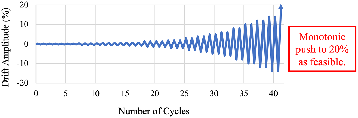
Deformation-controlled loading protocol for cripple wall experiments.
In both experimental programs, key measurements were taken during the tests to aid in generating global hysteretic curves for each specimen. In addition, local displacements and loads were monitored, the latter included direct axial measurements at anchor bolts. Analog measurements were correlated with physical damage evolution captured extensive video and photographic documentation taken throughout the tests.
Small-component testing program: key results
The following section presents key findings from the small-component testing program with attention toward the strength, stiffness, drift capacity, and hysteretic energy dissipation of the various specimens. The stiffnesses of the cripple walls are calculated as the secant stiffness associated with the relative drift at 80% of the prepeak lateral strength. The relative drift accounts for only the displacement imposed on the cripple wall and removes any relative displacement (slip) between the sill plate of the cripple wall and the foundation. Herein, findings presented a focus on comparing the performance of cripple walls with different exterior finishes, retrofit condition, and cripple wall height. Additional findings pertaining to the anchorage condition, applied axial load, boundary conditions, and loading protocol can be found in Schiller et al. (2020a, 2020b, 2020c, 2020d).
Existing specimens
In Figure 3, the envelope of the hysteretic response for lateral force versus relative lateral drift and displacement of existing 2-ft-tall cripple walls with various exterior finishes is presented. Notably, among the exterior finishes considered, the strongest cripple walls tested were those finished with diagonal sheathing. Both the cripple wall finished with stucco over diagonal sheathing and horizontal siding over diagonal sheathing reached lateral strengths more than 80% larger than the next strongest exterior finish material, which was stucco over horizontal siding. It was anticipated that specimens finished with stucco over diagonal sheathing would be among the strongest exterior finish tested; however, during testing, cross-grain splitting of the sill plate and fracturing of the anchor bolts occurred. This resulted in the failure of the cripple wall at its sill anchorage prior to fully mobilizing the strength of the diagonal sheathing. Fracturing of the anchor bolts also occurred with the horizontal siding over diagonal sheathing specimen, however, at a larger drift amplitude. Anchor bolt fracture was a failure mode only observed with specimens containing diagonal sheathing, demonstrating that the sill plate and anchorage were the weak link for cripple walls with diagonal sheathing. Nonetheless, specimens constructed with diagonal sheathing had the lowest drift capacity of any of the exterior finishes tested. It is important to note that specimens with diagonal sheathing observed a highly asymmetric response, as these sheathing boards are placed a nail-shank-wide gap during installation, thus each sheathing element observes a closure in this gap in one direction (push) and an opening in this gap upon loading in the opposing direction (pull). This manifests in added strength due to bearing when the gap between sheathing elements closes (see Figure 3b). All other exterior finished specimens observe nominally symmetric hysteretic response.
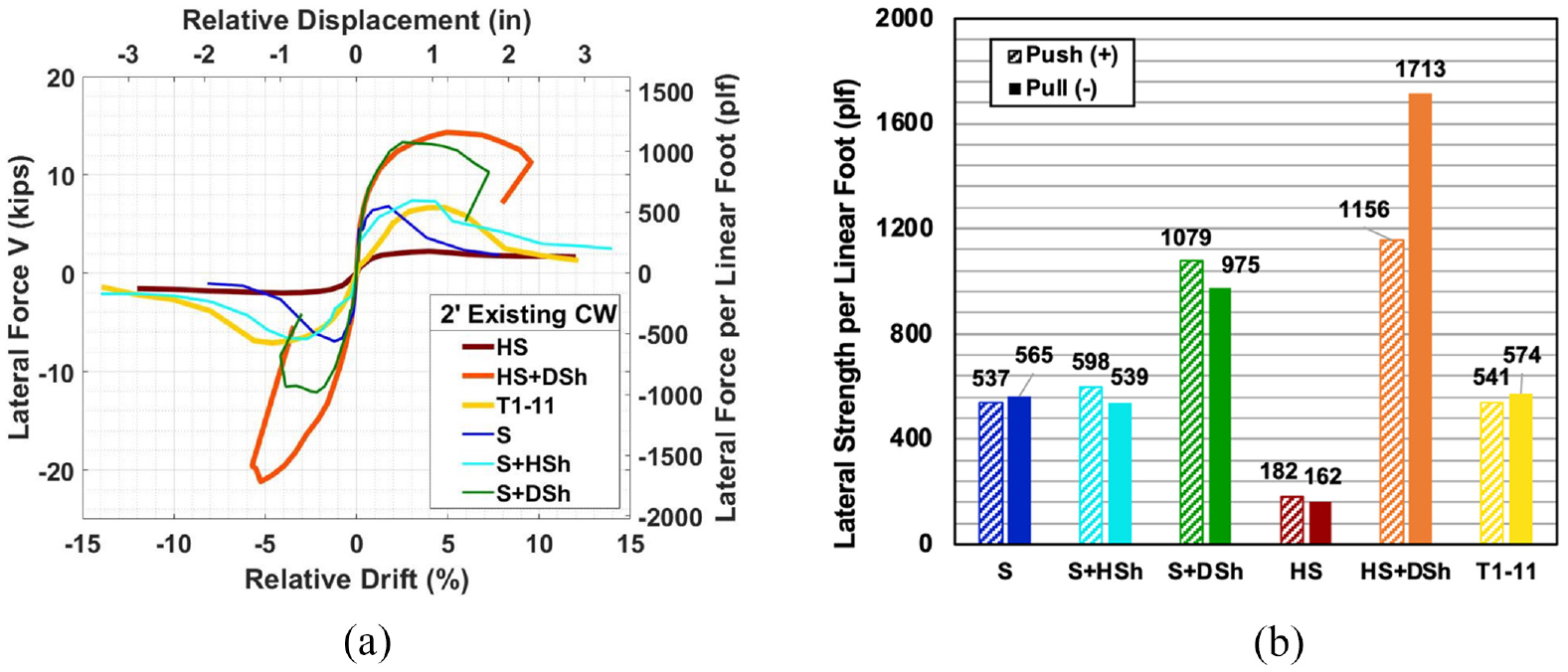
Comparison of existing 2-ft-tall cripple walls with various exterior finishes, (a) envelope of lateral force versus relative drift hysteresis and (b) lateral strength per linear foot.
By far the weakest exterior finish tested was horizontal siding over framing. The peak capacity of this specimen was only 30% of the capacity of the next weakest exterior finish (stucco over framing). However, horizontal siding had the largest drift capacity of any exterior finish due to the flexible nature of the cripple wall, which produced the lowest secant stiffness of all exterior finishes. Since the siding boards were orientated parallel to the direction of the imposed load and acted as discontinuous panels, the cripple wall gained the majority of its lateral resistance through the moment couples developed between the nails fastening the boards to the framing. Stucco over framing and stucco over horizontal sheathing reported similar peak lateral loads; however, the drift capacity of the stucco-only cripple walls was considerably smaller than that of the stucco over horizontal sheathing finished cripple walls. This was a result of the brittle nature of the stucco face. As the imposed displacement increased, the stucco panel would detach from the furring nails fastening it to the framing and/or sheathing. Visually, the stucco would appear to skirt out as the detachment started at the sill plate and would move up the height of the cripple wall. When sheathing was present, a portion of the imposed displacement was carried by the sheathing material allowing for the cripple wall to reach larger drift amplitudes prior to detachment of the stucco. However, the stucco over framing was the stiffest exterior finish type tested due to the rigidity of the stucco. T1-11 wood structural panels performed in the middle in terms of strength, stiffness, and drift capacity compared with the other exterior finish materials.
Three types of exterior finishes were tested in the 6-ft-tall cripple wall configuration, namely: horizontal siding over framing, stucco over framing, and T1-11 wood structural panels. In Figure 4, the envelope of the hysteretic response for lateral force versus relative lateral drift and displacement of existing 6-ft-tall cripple walls with various exterior finishes is presented. Among these, the strongest and stiffest exterior finish tested was stucco over framing; however, it also had the lowest drift capacity of any of the exterior finishes tested. This specimen observed more than a 70% increase in lateral strength compared with the T1-11 finished cripple wall and nearly a 600% increase in strength compared with the horizontal siding finished specimen. Similar to the 2=ft-tall specimens, the horizontal siding finished cripple wall was the weakest specimen tested. The lateral strength of the 6-ft-tall specimen was around half that of the 2-ft-tall specimen. In addition, the 6-ft-tall horizontal siding cripple wall was the most flexible cripple wall tested, resulting in the largest drift capacity of any specimen tested. At the end of the cyclic loading protocol, this specimen had lost only 5% of its lateral strength. The large difference in strength between the two specimens can be attributed to the following factors: (1) increased bearing of the trim and siding boards at the ends of the 2-ft-tall specimen on the foundation compared with the 6-ft-tall specimen, (2) increased overturning resistance of the frame for the 2-ft-tall specimen, and (3) reduction in the moment couple between siding board fasteners for the 6-ft-tall specimen due to a slightly reduced spacing between nail pairs compared with the 2-ft-tall specimen.
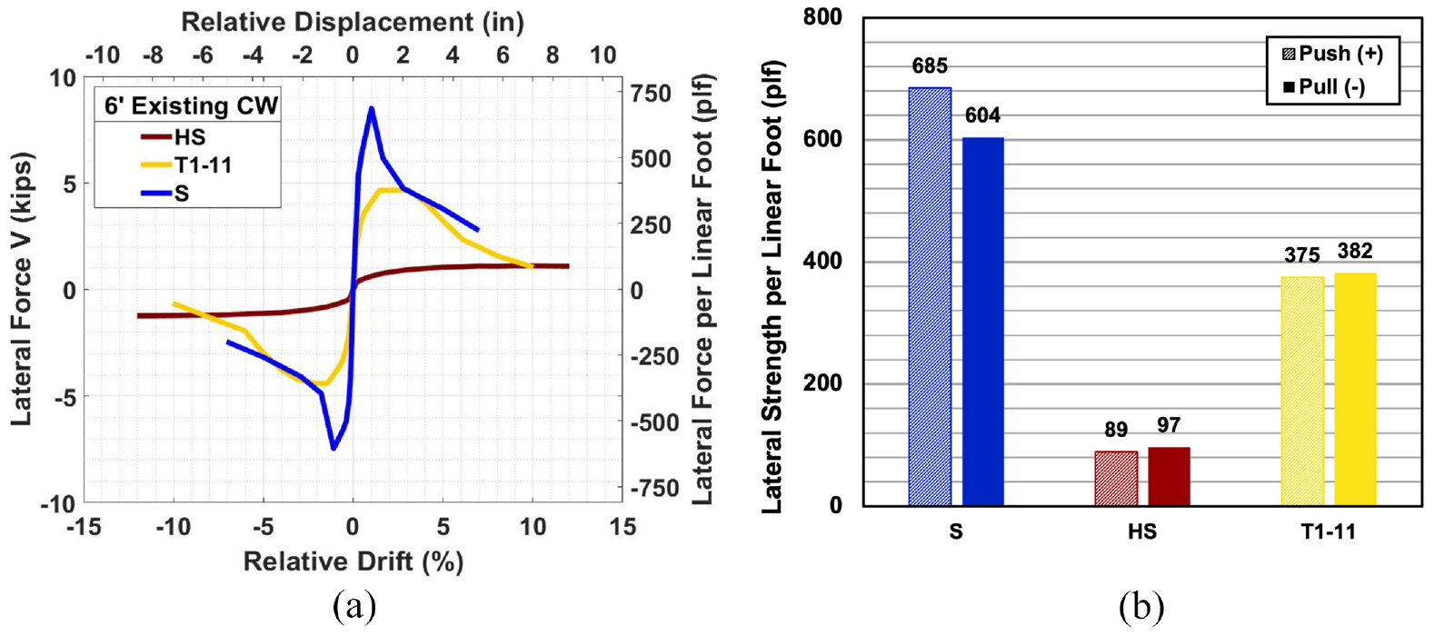
Comparison of existing 6-ft-tall cripple walls with various exterior finishes (a) envelope of lateral force versus relative drift hysteresis and (b) lateral strength per linear foot.
Similar to the 2-ft-tall specimens, the T1-11 finished cripple wall performed in the middle in terms of strength, stiffness, and drift capacity. Compared with its 2-ft-tall counterpart, the 6-ft tall T1-11 specimen observed about 30% lower lateral strength. There was a reduction in drift capacity for the 6-ft-tall specimens, which was caused by the increased nail distortion for the taller specimens as their displacement imposed at each drift amplitude was larger. T1-11 panels, like plywood, have substantial resistance to shear distortion; therefore, the panel-to-frame fasteners are distorted more for the taller cripple wall at a given drift amplitude since the displacement is three times as much for the taller walls. The increased nail distortion caused failure due to a tear out of fasteners located in the thinner sections of the panels before the fasteners in the thicker sections had been fully mobilized. This contributed to an increase in stiffness for the taller specimen but also a decrease in strength. The 6-ft-tall stucco finished cripple wall was the only existing cripple wall to experience an increase in strength compared with its 2-ft-tall counterpart. For existing 6-ft-tall cripple walls, only those with stucco over framing finish experienced an increase in strength, an increase of 16% over its 2-ft-tall counterpart. The increase in strength was due to the increased number of furring nails for the taller specimen. A direct comparison of the ratio between the increase in furring nails and the increase in strength is difficult to quantify as the stucco detaches from furring nails at various drift amplitudes; therefore, the furring nails are not fully mobilized at the same drift amplitude.
Retrofitted specimens
Nominally identical specimens were constructed for each exterior finish type and retrofit using the aforementioned FEMA P-1100 prescriptions. Results from cyclic loading of these specimens demonstrate the dramatic impact of retrofit application to the existing as-built cripple wall specimens tested. For example, Figure 5a shows an overlay of the lateral force—relative drift hysteresis of 2-ft-tall horizontal siding finished cripple walls, while Figure 5b shows the same for 2-ft-tall stucco over horizontal sheathing finished cripple walls. Within each figure, the existing, nominally identical, specimen is overlaid with the retrofitted specimen. The significant increase in strength, stiffness, and deformation at salient lateral force values is apparent for both exterior finish types. Notably, the retrofitted specimens’ hysteretic response is dominated by the presence of retrofit, with little influence of the original exterior finish type (see Figure 5a and b) stucco and horizontal siding retrofitted specimens appear nearly identical. The impact of such retrofit is largely independent of the type of exterior finish installed on the cripple wall specimen. The exception to this were the diagonally sheathed specimens. Specimens with diagonal sheathing underlying either stucco or horizontal siding experience significant increases in strength and stiffness due to the combination of lateral resistance offered by both the diagonal sheathing and the overlaying exterior finish (see Figure 6). The significant lateral strength of these specimens resulted in an abrupt failure of anchor bolts for each of the retrofitted diagonally sheathed specimens.
Overlay of lateral force—relative drift hysteretic response of 2-ft-tall existing and retrofit cripple walls: (a) stucco-only exterior finish and (b) horizontal siding-only exterior finish.
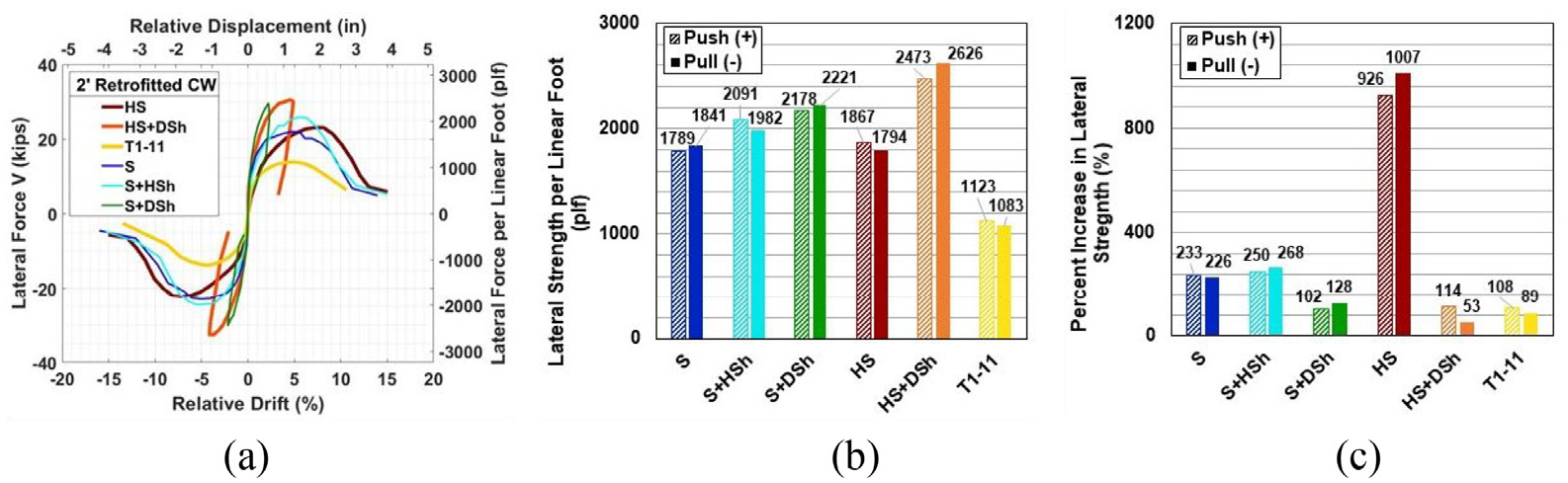
Comparison of retrofitted 2-ft-tall cripple walls with various exterior finishes: (a) envelope of lateral force versus relative drift hysteresis, (b) lateral strength per linear foot, and (c) percent increase in lateral strength of retrofitted cripple walls. Note that the increase in part c is taken as (Vu,retrofit −Vu,existing)/Vu,existing reported in percentage.
Evaluating the relative contribution of retrofit to the existing specimen lateral response, the largest percent increase in strength was for the horizontal siding finished specimens, which realized more than a 900% increase in strength. The smallest percent increase in strength was for the cripple walls with diagonal sheathing and the T1-11 finished cripple wall. For the former, the relative increases were not as significant due to the already large amount of strength that was provided by the diagonal sheathing. In the case of the T1-11 finished specimen, the strength doubled, which was expected due to the nail spacing reducing from 8 to 4 in. on the center. The percent increase in strength of each of the 2-ft-tall specimens is shown in Figure 6c.
For the three types of exterior finishes tested at 6 ft tall, their retrofitted counterparts were also tested. In Figure 7, the envelope of the hysteretic response for lateral force versus relative lateral drift and displacement of retrofitted 6-ft-tall cripple walls with various exterior finishes is presented. From Figure 7a, it can be seen that the stucco and the horizontal siding finished specimens had similar drift capacities and peak strength, while the stucco finished specimen was stiffer than the horizontal siding finished specimen. However, compared to the existing versions of the cripple walls, the horizontal siding finished specimen had the largest increase in strength, over an 1800% increase. For the stucco finished specimen, this increase was around 180%. The largest increase in drift capacity was experienced by the stucco-finished specimen. For the existing version, peak strength was achieved at 1.1% relative drift, whereas for the retrofitted specimen, it was achieved at 2.9% relative drift. As with the 2-ft-tall horizontal siding finished specimens, the drift capacity was reduced with the addition of the retrofit, but the strength was larger at each drift amplitude. For the T1-11 finished specimen, the strength increased by 125% along with increases in the drift capacity and the stiffness. A comparison of the percent increases in strength for the 6-ft-tall cripple walls can be seen in Figure 7c.
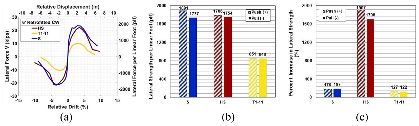
Comparison of retrofitted 6-ft-tall cripple walls with various exterior finishes: (a) envelope of lateral force versus relative drift hysteresis, (b) lateral strength per linear foot, and (c) percent increase in lateral strength of retrofitted cripple walls.
Small- and large-component results comparison
Among the 28-cripple wall-only tests performed within the small-component program, 11 were 2 ft tall and finished with stucco over horizontal sheathing. An increased focus was given to this height and finish style as it was determined to be one of the most common exterior finish types and heights for cripple walls within California’s housing stock (Reis, 2020). Thus, this height and exterior finish style were defined as the baseline specimen, with variations in boundary conditions imposed to determine optimal boundary conditions to be used for the remainder of the specimens (see Table 1). Of the 11 baseline height and finish cripple walls tested, two matched the detailing of the cripple walls constructed in the large-component testing program, one built in the existing configuration and the other built in the retrofitted configuration. Other boundary condition configurations of the cripple wall-only assemblies provided a basis for identifying upper and lower bounds of lateral strength and deformation capacity, each instructive for numerical modeling. All additional configurations and their associated specimen names are provided in Table 2. For large-component specimens AL-1 and AL-2, bottom boundary condition d was used, which consisted of both finish materials being seated outboard of the foundation and the stucco extending 8-in down the face of the foundation. It is noted that an extension of stucco down the face of a concrete footing was common in most housing units within older residential construction, whereas the termination of stucco at weep screed became common in the 1980s. Existing small-component specimen A-20 was constructed with details common to large-component specimen AL-1, and retrofitted small-component specimen A-19 was constructed with details common to large-component specimen AL-2. The exception for the retrofitted specimens was that Specimen A-19 did not have the extension of the stucco down the face of the foundation, as it was observed that the addition of the retrofit dominates the response of the cripple wall, thus the absence of the stucco extension was assumed to have a little impact on the comparison of the results among small and large retrofitted specimens.
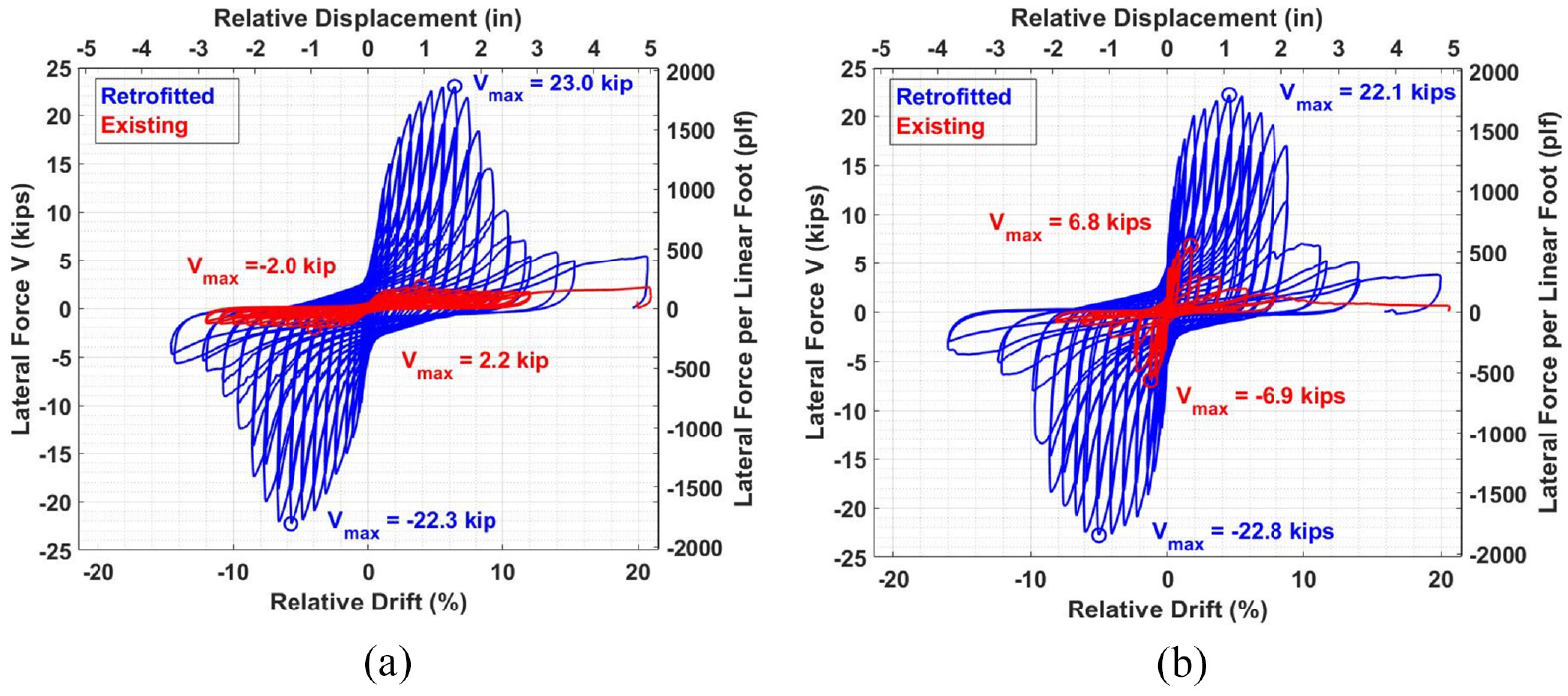
For the existing specimens in the small-component testing program finished with stucco over horizontal sheathing, there was a large range in the lateral strength per linear foot. For the most comparable specimens, the lateral strength of the small-component test was only 44% of the lateral strength of the large-component test. The relative drift at peak strength was similar for both tests, 2.8% relative drift for Specimen A-20, and 2.4% relative drift for Specimen AL-1, see Schiller et al. (2020a). Figure 8a provides an overlay of the lateral force versus relative drift hysteresis for Specimen A-20 and Specimen AL-1. From this figure, it is apparent that the drift capacity of the two specimens is similar; however, the lateral strength and stiffness (particularly prepeak) of the large-component cripple wall-first-story assembly were significantly larger. The increased strength and pre-peak stiffness were a result of the continuity of the stucco from the cripple wall into the first story, the continuity of the stucco around the corners of the 3D assembly, and a stronger bond between the stucco extension and the foundation. While Specimen A-20 was constructed with the same stucco extension, the bond between the stucco and the foundation was minimal following the installation of the specimen into the testing apparatus. During testing of Specimen AL-1, there was an audible pop that could be heard as an appreciable region of stucco bond to the foundation detached, and subsequently, the furring nails were pulled out from the sill plate. Simultaneously, an abrupt loss in strength was observed for Specimen AL-1 (see Figure 8a).
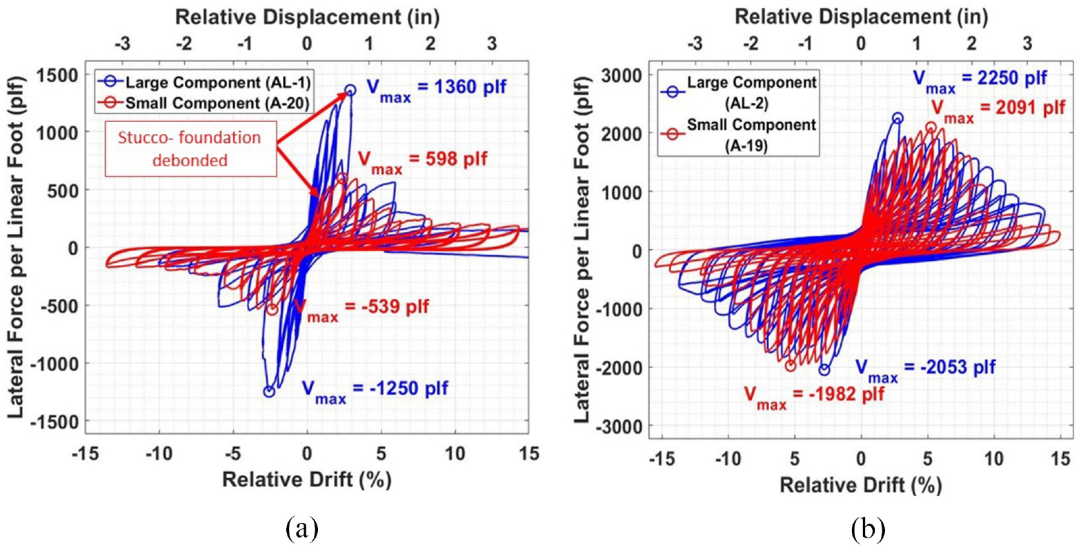
Comparison of lateral force versus relative drift hysteresis (a) existing specimens A-20 and AL-1 and (b) retrofitted specimens A-19 and AL-2.
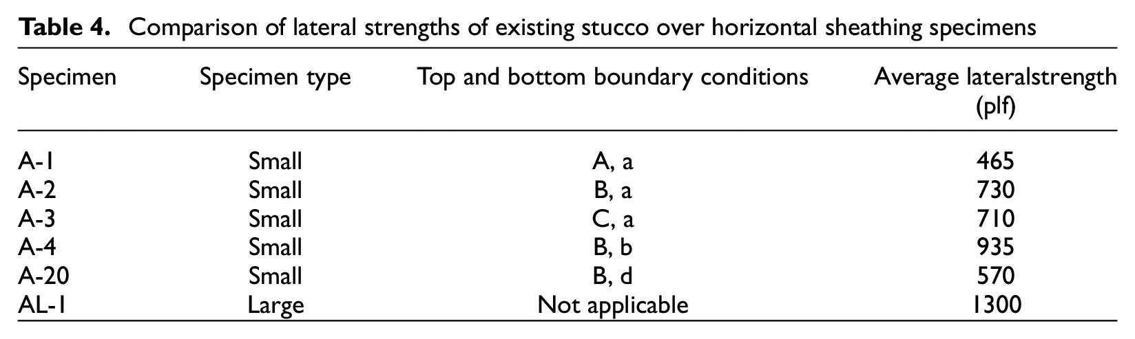
Overall, for the existing specimens, the small-component cripple wall-only tests were considerably weaker than the large-component cripple wall-first-story assembly (see Table 4). The strongest cripple wall with the closest resemblance with the large-component specimen was A-4, which had a peak capacity of 935 plf on average between the two loading directions, approximately 70% of the capacity of Specimen AL-1. However, for Specimen A-4, the finish materials were both bearing on the foundation, resulting in restrained rotation and increased strength due to bearing, a less likely configuration in practice, envisioned to facilitate an upper bound within the small component program. Due to the bearing condition of the finish materials, Specimen A-4 attained lateral strength at 3.7% relative drift, which was slightly larger than Specimen AL-1. Regardless of the boundary conditions for the small-component cripple wall-only specimens, the relative drift at peak strength was similar to that of the large component cripple wall-first-story specimens. The weakest of the stucco over horizontal sheathing finished cripple walls, Specimen A-1, attained less than 40% of the capacity of Specimen AL-1; however, its lateral strength was attained at 3.0% relative drift, which was similar to the large component test. Specimen A-1 was constructed without built-up corners and a further spaced furring nail arrangement along the top plates, thus the most limited boundary continuity along all edges of the small-scale specimen. As a result, from a construction replication perspective, Specimen A-1 represents a lower-bound, Specimen A-20 represents an optimal estimate, and Specimen A-4 represents an upper-bound. This general trend translated to anticipated ranges in strength, when compared with the large-component specimen.
Comparison of lateral strengths of existing stucco over horizontal sheathing specimens
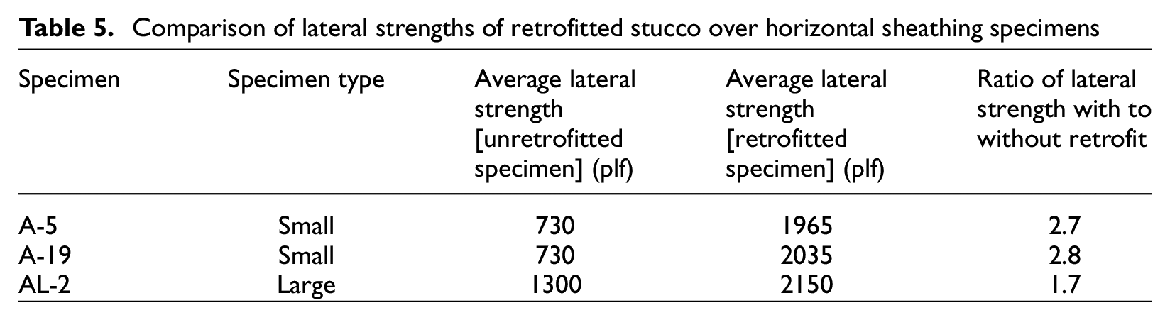
For the retrofitted cripple walls with stucco over horizontal sheathing, the peak strength was similar between the small-component cripple wall-only assembly, Specimen A-19, and the large-component cripple wall-first-story assembly, Specimen AL-2. Figure 9b provides an overlay of the lateral force versus relative drift hysteresis for Specimen A-19 and Specimen AL-2. While the peak strengths were within 5% of each other, 2035 and 2150 plf on average for Specimens A-19 and AL-2, respectively, the relative drift at strength varied considerably. For the retrofitted large component cripple wall-first-story assembly, peak strength was achieved at 2.8% relative drift, which was the same as the existing detailed specimen. For the retrofitted small-component cripple wall-only assembly, the drift capacity significantly increased compared to its existing counterpart, increasing from 2.4% relative drift to 5.3% relative drift. During the monotonic push following the cyclic loading protocol for the large component specimen, a slip plane formed between the upper and lower cripple wall top plates of the cripple wall, resulting in the diaphragm and upper top plate moving a considerable distance relative to the lower top plate. This slip is largely attributed to the staggering of sheathing nails between the upper and lower top plates as well as the light nailing interconnecting the top plates. This failure mechanism was not observed for the cripple wall-only specimen due to the presence of lag screws connected to the loading beam, which penetrated all of the top plates. Table 5 summarizes the lateral strength of the retrofitted specimens and their existing or unretrofitted counterparts along with the ratio of the strength increase provided by the retrofit. The ratio of lateral strength increase for the small component cripple wall-only specimen was significantly larger than that of the large component cripple wall-first-story specimen, 2.8 compared with 1.7. The addition of the retrofit increased the peak capacity of the cripple wall-only assembly by 1305 plf, whereas the increase for the cripple wall-first-story assembly was 850 plf. The reduction in added capacity for Specimen AL-2 may be attributed to the staggered nailing detail of the plywood to the top plates as well as the inability of the plywood panels to rotate when displaced, which was not the case for Specimen A-19. Regardless, in both scenarios, the addition of the FEMA P-1100 retrofit demonstrated significant increases in the strength of the cripple walls.
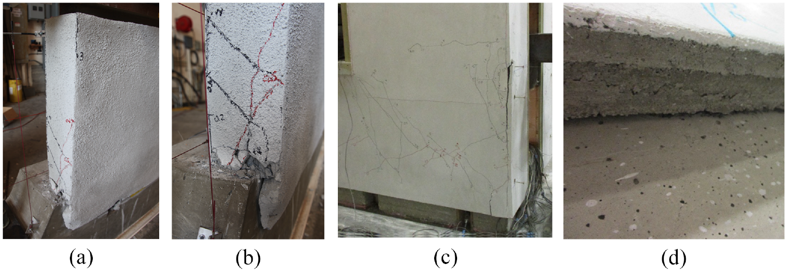
Damage observations at strength (a and b) cripple-wall only (small) specimens; (c and d) cripple wall-first story (large) specimens: (a) stucco cracking and (b) detachment at corner, Specimen A-20 (+2.4% relative drift); (c) stucco cracking at corner and (d) detachment at bottom, Specimen AL-1 (+2.8% relative drift).
Comparison of lateral strengths of retrofitted stucco over horizontal sheathing specimens
The observable damage characteristic to the exterior finish materials was consistent for both the cripple wall-only and cripple wall-first story specimens (see Figure 9). At low displacement amplitudes, vertical and diagonal cracks formed along the stucco with a concentration of cracking at the corners. As the imposed displacement increased, the width of the cracks also increased and spalling of the stucco occurred. For the existing specimens, when strength was reached, the stucco had detached from the furring nails on the sill plate as well as the furring nails at the bottom of the studs. Visually, it appeared that the stucco panel was skirting outward from the sheathing and studs (see Figure 9). With increasing displacement, the stucco continued to detach from the furring nails higher up the studs until the only attachment on the cripple wall was to the top plates. At this point, the metal lath had ruptured at the corners, significant spalling of the stucco occurred, and the sheathing boards were visible. Loss of strength was primarily attributed to the detachment of the stucco from the furring nails along the cripple wall. For the retrofitted specimens, at early displacement amplitudes, rotation of the plywood panels was observed. As the displacement increased, pullout and tear through of the fasteners as well as crushing of the plywood panels at the corners occurred. Due to the constrained nature of the plywood panels for the cripple wall-first-story specimen, the damage to the panels was not as significant as that observed in the cripple wall-only specimen. The reduction in damage was also a result of the slip plane developed between the top plates which caused more of the imposed displacement to be taken between the top plates instead of on the plywood panels. Ultimately, loss of strength occurred when a large portion of the fasteners pulled through, pulled out, or tore through the plywood panels.
Conclusions
This article summarizes the scope and offers a highlight of key results of a small- and large-component testing program conducted within the PEER-CEA project. Particular emphasis is given to presenting an overview of the impact of exterior finishes, application of retrofit, and comparing results of like-detailed specimens tested within both the small-scaled program to those of the large-scale program. The main conclusions from the experimental programs are as follows:
Impact of exterior finish
The horizontal siding was the weakest exterior finish tested under the unretrofitted condition. Notably, the 2-ft-tall specimen attained an average lateral load of 170 plf, and the 6-ft-tall specimen reached about 90 plf. In comparison, the nearest strength specimen among the 2-ft-tall cripple walls was finished with stucco over framing, and attained a lateral strength of 550 plf, while the weakest exterior finish for the 6-ft-tall specimens (T1-11), the lateral strength was 379 plf.
Diagonal sheathing emerged as the strongest sheathing material used with existing construction. Specimens with stucco over diagonal sheathing and horizontal siding over diagonal sheathing attained the highest capacity among those exterior finishes considered, about 1030 plf for stucco over diagonal sheathing and 1440 plf for horizontal siding over diagonal sheathing. In addition, existing cripple walls with diagonal sheathing were the only cripple walls to experience anchor bolt failure and/or cross-grain splitting of the sill plate.
The strength of 2-ft-tall cripple walls finished with stucco over framing, stucco over horizontal sheathing, and T1-11 wood structural panels were all within 5% of each other, with an average of about 550 plf.
Stucco over framing was the stiffest exterior finish but also had the lowest drift capacity of any exterior finish tested.
Impact of FEMA P-1100 prescriptive retrofit design
All cripple walls retrofitted according to the FEMA P-1100 guidelines showed increased strength, stiffness, and energy dissipation, irrespective of either wet or dry exterior finishes. In most cases, the retrofit increased the drift capacity of the cripple wall.
The largest increase in lateral strength was observed for those retrofitted specimens with an exterior horizontal siding finish. For example, the retrofitted 2-ft-tall specimen increased in strength from about 170 to 1830 plf, and the retrofitted 6-ft-tall specimen increased in strength from 90 to 1770 plf, amounting to around a 10-fold and 20-fold increase, respectively.
Besides the horizontal siding specimens, the wet finished retrofitted specimens observed the largest increases in strength, on average between 115% and 260%. The stucco finished specimen retrofitted 2-ft-tall increased in strength by about 230%, and the stucco horizontal sheathing finished 2-ft-tall specimen increased in strength by around 260%.
Small- and large-component specimens comparison
The lateral strength of the large-component specimen was significantly higher than that of the small-component specimens, 570 versus 1300 plf on average between both loading directions. This is largely attributed to a combination of the continuity of the stucco from the cripple wall to the first floor, the excellent construction quality and substantial bond between the stucco and the foundation, and the continuity of the stucco around the entire 3D large-component specimen. Therefore, the large-component specimen is viewed as representing a high but achievable upper bound of lateral strength.
Small-component specimen A-20, which best emulated the boundary conditions of large component specimen AL-1, attained similar relative drifts at lateral strength with 2.8% relative drift for Specimen A-20 and 2.4% for Specimen AL-1.
The lateral strength of the retrofitted small- and large-component specimens was quite similar, 2035 plf for the small-component specimen and 2150 plf for the large-component specimen; in each case, the specimens’ behavior was dominated by the retrofit plywood and fasteners. However, the increase in strength provided by the FEMA P-1100 retrofit was significantly larger for the cripple wall-only specimens. This may be due in part to the detailing of the large-component specimen retrofit plywood, which may have prevented the retrofit sheathing from achieving full capacity.
As a consequence, the drift capacity of the cripple wall-only specimen was significantly larger than the cripple wall-first floor specimen, with the former reaching strength at 5.3% relative drift and the latter at 2.8% relative drift.
Footnotes
Acknowledgements
This research study was funded by the California Earthquake Authority (CEA). The support of the CEA and all project team members within the PEER-CEA project is gratefully acknowledged. The opinions, findings, conclusions, and recommendations expressed in this publication are those of the authors and do not necessarily reflect the views of the CEA, Pacific Earthquake Engineering Research Center (PEER), project team members, or the Regents of the University of California.
Declaration of conflicting interests
The author(s) declared no potential conflicts of interest with respect to the research, authorship, and/or publication of this article.
Funding
The author(s) received no financial support for the research, authorship, and/or publication of this article.