
Abstract
This study proposes a practical fragility-oriented approach for the seismic retrofit design of case-study structures. This approach relies on mapping the increase of the global displacement-based ratio of capacity to life-safety demand (CDRLS) to the building-level fragility reduction. Specifically, the increase of CDRLS due to retrofitting is correlated with the corresponding shift in the fragility median values of multiple structure-specific damage states, observing that a pseudo-linear trend is appropriate under certain conditions. Accordingly, a practical approach is proposed to fit such a (structure-specific) linear trend and then use it by first specifying the desired fragility median and subsequently finding the corresponding target value of CDRLS that must be achieved through retrofit design. The validity of the proposed approach is illustrated for an archetype reinforced concrete (RC) structure not conforming to modern seismic design requirements, which has been retrofitted using various techniques, namely, fiber-reinforced polymers wrapping of columns and joints, RC jacketing, and steel jacketing.
Keywords
Introduction
Many existing reinforced concrete (RC) buildings in earthquake-prone regions do not conform to modern seismic design codes as they were designed/built to resist gravity loads only. As a result, those structures are vulnerable to severe damage or even collapse under moderate-to-high ground-shaking intensity levels (e.g. De Luca et al., 2018). This has led to significant economic and life losses, as demonstrated by numerous past earthquakes (e.g. Mazzoni et al., 2018; Ricci et al., 2011; Stewart et al., 2018). Structural retrofit is often necessary to mitigate the consequences of earthquakes on such buildings and improve their seismic performance. This approach has become quite popular in recent times due to ease of construction and cost-effectiveness compared with other drastic solutions like demolition and replacement. In general, retrofit strategies aim to either modify key structural properties such as strength, ductility, and stiffness—as depicted in Figure 1—or reduce seismic demand. Several techniques (systems) can be used to achieve one or more strategies. For instance, adding RC shear walls (e.g. Kaplan et al., 2011; Miano et al., 2017) or bracing (e.g. Badoux and Jirsa, 1990; Freddi et al., 2013, 2021; Gutiérrez-Urzúa et al., 2021) to existing buildings notably improves stiffness and lateral strength. In contrast, base isolation is applied to reduce seismic demand by decoupling the horizontal motion of a structure and that of the ground (e.g. Natale et al., 2021).
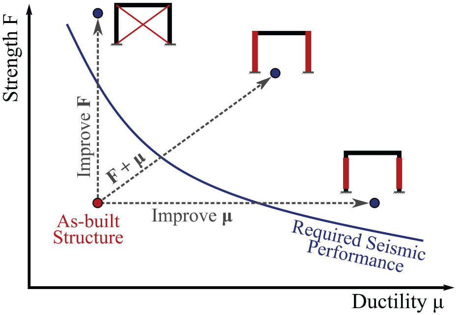
Effects of different retrofit strategies on seismic performance.
Many challenges may arise in adopting the above techniques. Those challenges are related to the architectural compatibility of the intervention, its invasiveness, the need to modify existing foundations or add new ones, the high implementation costs, and long work duration. Therefore, less-invasive retrofit techniques are more widespread. Examples include wrapping structural elements with fiber-reinforced polymers (FRP) and jacketing columns using steel or RC jackets, which enhance ductility and/or strength. These local techniques are fundamentally less expensive, and they pose a minimal degree of invasiveness/business interruption compared with RC shear walls or bracing. It should be noted that structural retrofit can improve lateral sway mechanisms of buildings, especially if they experience non-ductile local sway ones (e.g. joint failure, soft story). Such mechanisms can be shifted to global ones such as mixed sway, where plastic hinges develop in different structural elements (e.g. beams, columns, joints), or even beam sway, where plastic hinges only form in beams and column bases.
While retrofitted structures are generally expected to perform better against earthquake-induced ground shaking, field observations for such buildings under actual seismic events are still scarce (O’Reilly and Sullivan, 2018). This indicates the lack of sufficient empirical seismic fragility and vulnerability models in the literature, which are essential for applications aimed to select/design/implement seismic risk reduction strategies and ultimately enhance the resilience of earthquake-prone communities. This also demonstrates the need to derive such models numerically adopting nonlinear dynamic analysis methods, which usually require a large number of analyses, practically incompatible with the preliminary/conceptual design process. Moreover, especially in the seismic risk assessment of building portfolios, retrofit solutions are often designed based on engineering judgment using simplified models without accounting for different alternatives and/or performance objectives. Such a practice does not grant an analyst the complete control over the reduction in seismic fragility/loss estimates and makes it challenging to optimize the results.
Accordingly, a practical and relatively flexible approach is needed to fill this gap, enabling one to control and specify the desired seismic fragility level and returning the corresponding “nominal” performance to be achieved through retrofit design. Such a “nominal” performance is usually assessed by using simple metrics quantified within the acceleration–displacement response spectrum (ADRS) space, thus requiring pushover-based analysis methods. One common metric is the displacement-based global ratio of capacity to life-safety (LS) demand of a similar new structure
The above issues have attracted many research efforts in the past few decades, but a limited number of studies are available. Although a detailed review of such studies is beyond the scope of this article, a few are briefly discussed to provide the reader with some background on the topic. Most of the past research focused on the experimental investigation of different retrofit techniques and developing analytical and numerical models to simulate their effect on existing structural elements and/or systems. For instance, some studies investigated the effects of steel jackets on RC columns experimentally and developed design procedures (e.g. Aboutaha et al., 1996, 1999; Alvarez et al., 2018; Priestley et al., 1994), while others explored FRP retrofitting (e.g. Alvarez et al., 2018; Lam and Teng, 2003; Priestley and Seible, 1995; Seible et al., 1997) and RC jacketing for columns (e.g. Priestley et al., 1996; Rodriguez and Park, 1994).
On the contrary, some studies developed fragility relationships considering FRP, RC jacketing, base isolation, and adding shear walls (e.g. Cardone et al., 2019; Liel and Deierlein, 2013). However, the fragility relationships in these studies accounted for collapse only, without considering other damage states (DSs), which may significantly contribute to earthquake-induced losses for low-to-moderate ground shaking levels. Moreover, the retrofit solutions in some studies were either applied based on engineering judgment, that is, without appropriately accounting for structure-specific seismic deficiencies or specific performance objectives (e.g. Liel and Deierlein, 2013), or considering solely one, rather than different, performance objective (e.g. Cardone et al., 2019; Gentile and Galasso, 2021b). Contrarily, other studies considered applying different retrofit techniques with varying intervention levels to achieve various performance objectives (e.g. Harrington and Liel, 2021; Ligabue et al., 2018), but only collapse fragility relationships were evaluated. These studies also attempted to map different performance metrics to decision variables of interest, such as collapse risk and/or seismic losses, to provide insight into their correlation.
Based on the aforementioned discussion, the current study proposes a practical fragility-oriented approach based on mapping the increase of CDRLS due to retrofitting to the reduction of building-level seismic fragility. The proposed approach enables the selection of the desired fragility level and returns the required “nominal” structural performance in terms of
Fragility-oriented retrofit design
For this study, the nominal seismic performance of a structure of interest is quantified using
Retrofit generally aims to reduce seismic risk (for instance, in terms of the expected annual loss, EAL) to an acceptable level. Computing seismic risk, however, requires quantifying site-specific seismic hazard, fragility relationships, and damage-to-loss models. Since retrofit will mainly affect fragility estimates, it might be required to design numerous retrofit solutions, derive fragility relationships (based on NLTHA) for each one, and then evaluate the seismic risk until meeting the target level. Such a process can be quite impractical and/or infeasible. To tackle this issue, this study proposes a fragility-oriented approach that allows specifying the desired fragility level, represented by the median of the fragility relationship for a given DS
The proposed approach relies on the practical assumption that the relationship between
To apply the proposed fragility-oriented approach, it is practically required to obtain only three points in the
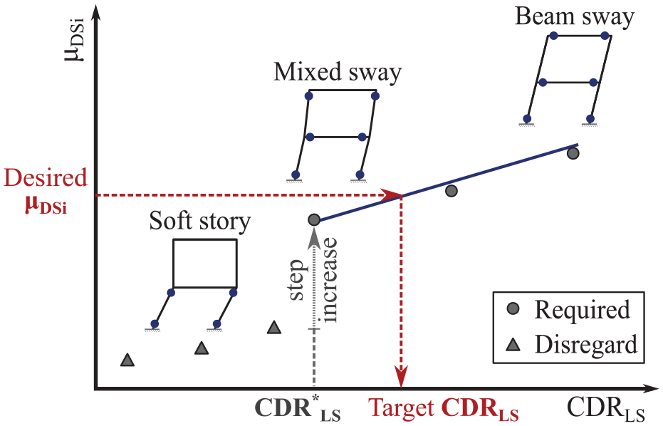
Schematics of the
Conversely, if the as-built structure shows an unfavorable local mechanism (i.e. soft-story), the retrofit design will likely aim to shift this mechanism to a beam-sway, or at least a mixed-sway one. Such a mechanism shift leads to an abrupt change in the slope of the power-law model, which appears as a step increase in the
Upon properly defining the three points and considering the above discussion, a linear model can be fitted for each DS, as shown in Figure 3. Those
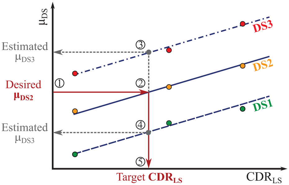
Conceptual illustration of the fragility-oriented approach for retrofit design.
It is important to recall that the
It is worth emphasizing that the desired fragility level specified at the start of the proposed approach can correspond to an acceptable level of risk/loss (e.g. EAL). In fact, the specified fragility level, combined with a damage-to-loss model and a site-specific seismic hazard, can be used to compute the resulting EAL. This can be finally compared with acceptable values selected by the designer. This check must be assured before evaluating the target
Finally, the proposed approach can also be advantageous to facilitate budget and resource allocation procedures needed for risk mitigation of building portfolios, mainly if the limited availability of financial resources constrains the decision-making process. This can be achieved by optimizing the levels of fragility that provide the best reduction in the overall seismic risk within the available budget and resources. Furthermore, the proposed fragility-oriented approach could be applied oppositely. Specifically, an analyst can design a retrofit solution, perform a pushover analysis to find the corresponding
Case-study application
The appropriateness of the linear models characterizing the
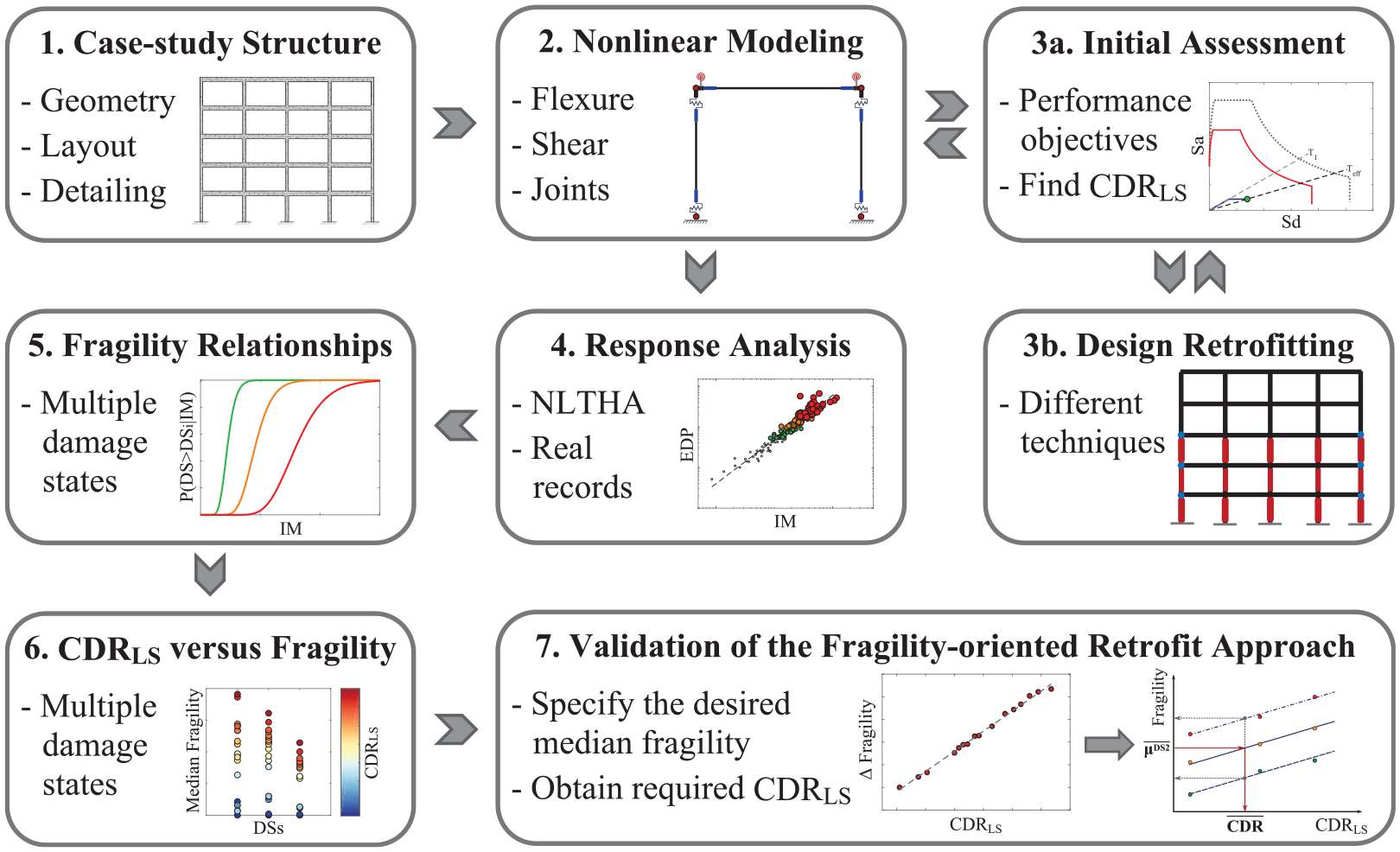
Flowchart for the analysis of the case-study structure and validation of the proposed fragility-oriented approach for retrofit design.
Case-study building
An older five-story, four-bay RC moment-resisting frame with a total height of 15 m and a uniform bay width of 4.5 m is considered, as shown in Figure 5. This frame is designed to resist gravity loads only according to the Royal Decree n. 2229 in Italy in 1939 (Consiglio dei Ministri, 1939), which regulated the design of RC frames until 1974. Following this decree, simulated design (e.g. Verderame et al., 2010) is performed to define the proportioning and detailing of the structural elements, using the allowable stress design.
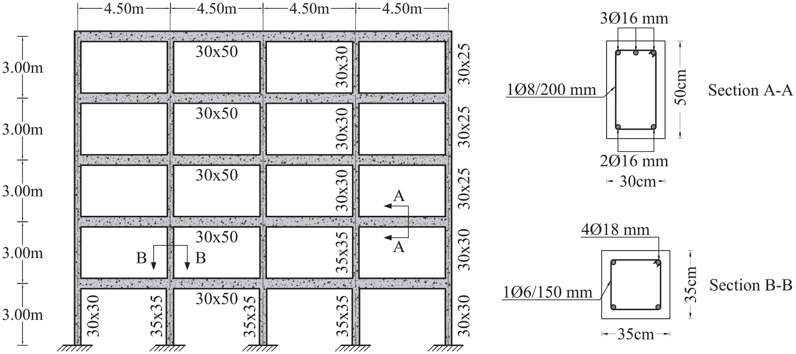
Layout of the case-study frame and sample cross sections (section dimensions are in centimeters).
It should be noted that buildings designed according to this decree constitute a considerable portion of RC structures in Italy. For instance, Rosti et al. (2021) investigated more than 2400 RC residential buildings in L’Aquila and Irpinia to derive empirical fragility relationships. They found that almost all buildings in Irpinia were built before the seismic classification in 1981, thus they were designed for gravity loads only. In contrast, most of the RC buildings in L'Aquila were built after the seismic classification in 1915, indicating that they have some seismic resistance. However, almost 35% of those were designed before 1981, i.e., using obsolete building codes that do not adopt modern seismic design requirements (Rosti et al., 2021). Similar observations were indicated by Del Gaudio et al. (2017) for L’Aquila upon investigating more than 7500 RC buildings. It is also interesting to note that 67% of L’Aquila’s considered buildings are mid-rise (three to five stories), whereas around 33% of the residential RC structures in Irpinia belong to such a category (Del Gaudio et al., 2017; Rosti et al., 2021).
Clearly, the frame resulting from the simulated design does not satisfy the modern seismic design provisions, such as capacity design and strong column–weak beam. Beams and columns are poorly confined, and those have a very low amount of longitudinal rebar (less than 1%). Moreover, the joints lack transverse reinforcement, use smooth bars, and improper anchorage (Calvi et al., 2002a, 2002b; Pampanin et al., 2002). This makes the frame susceptible to forming brittle failure mechanisms such as soft story, joint, and shear failure. Typical average values for the material properties are used, which are representative of that era. Specifically, the average concrete compressive strength
Considered retrofit techniques
Three retrofit techniques are investigated in this study: FRP wrapping, steel jacketing, and RC jacketing. Typical cross sections for columns retrofitted using these techniques are illustrated in Figure 6. FRP wrapping is used here to retrofit joints and columns to prevent any shear failure. It also provides a high level of confinement for columns, thus improving their ductility under extreme load conditions (e.g. Priestley and Seible, 1995; Seible et al., 1997). The contribution of FRP wrapping to the lateral stiffness and flexural strength is minimal because the unidirectional fibers are placed perpendicular to the longitudinal axis of columns.

Typical cross sections of a column retrofitted using (a) FRP, (b) steel, and (c) RC jacketing.
The selected FRP material consists of laminated precured sheets with high-strength carbon fibers (CFRP), which are wrapped around the full height of as-built columns. This type is among the most commonly used ones in the practice and literature (e.g. Alvarez et al., 2018; Cardone et al., 2019; Harrington and Liel, 2020, 2021; Natale et al., 2021). The elasticity modulus
Rectangular and elliptical steel jackets are another popular option to prevent the shear failure of columns. They can also increase lateral stiffness due to the isotropic steel properties (Alvarez et al., 2018). However, only elliptical (or circular) jackets are used in this study because they effectively improve confinement and ductility due to the continuous confining pressure they provide (Priestley et al., 1994). This technique can also offer some enhancement of flexural strength. Conversely, experiments demonstrated that rectangular steel jackets lose much of their confinement efficiency (e.g. Priestley et al., 1994, 1996). The adopted steel jacketing consists of full-height elliptical/circular jackets. The space between the jacket and retrofitted column can be filled with grout material or plain concrete (e.g. Alvarez et al., 2018; Priestley et al., 1994). The jackets are made of structural steel grade S235 with an average yield strength
RC jacketing is the most traditional and common technique in practice as it is characterized by a low cost and does not require specialized labor. It consists of encasing existing columns with a cast-in-place RC jacket to improve confinement, ductility, and both shear and flexural strengths. Continuous column jacketing in two consecutive floors also enhances joint behavior. The thickness of an RC jacket is mainly controlled by the size of longitudinal and transverse reinforcement to be used, in addition to the minimum cover requirement (e.g. Lizundia et al., 2006; Priestley et al., 1996). Compared with the other two techniques, RC jacketing poses the highest level of invasiveness. It can notably increase the size of existing columns and may require extending reinforcement through slabs, foundations, and joints. The adopted RC jacketing involves a full-height encasement of existing columns using cast-in-situ concrete, with the possibility of extending longitudinal rebar through foundations and slabs. RC jackets with a minimum thickness of 50 mm are adopted, with at least 4Φ14 mm for external columns and 4Φ16 mm for internal ones (Φ refers to the diameter). Hoops with Φ8 mm are used with a spacing not exceeding 150 mm. The concrete material is characterized by
Damage-state definition
Three structure-specific DSs are adopted to characterize different damage conditions reflecting the building’s performance level (PL). Each DS occurs when the structure attains a specific threshold defined with respect to an EDP. This study adopts the maximum interstory drift ratio (MIDR) as an EDP, which is a reliable and widely used proxy to quantify global structural and nonstructural damage (at least for drift-sensitive components). The MIDR thresholds for each DS are calibrated by assessing multiple measurable criteria during pushover analysis using a modal-pattern incremental load. These criteria are adapted from Aljawhari et al. (2020) and summarized in Table 1.
Criteria adopted for mapping of DSs: Aljawhari et al. (2020)
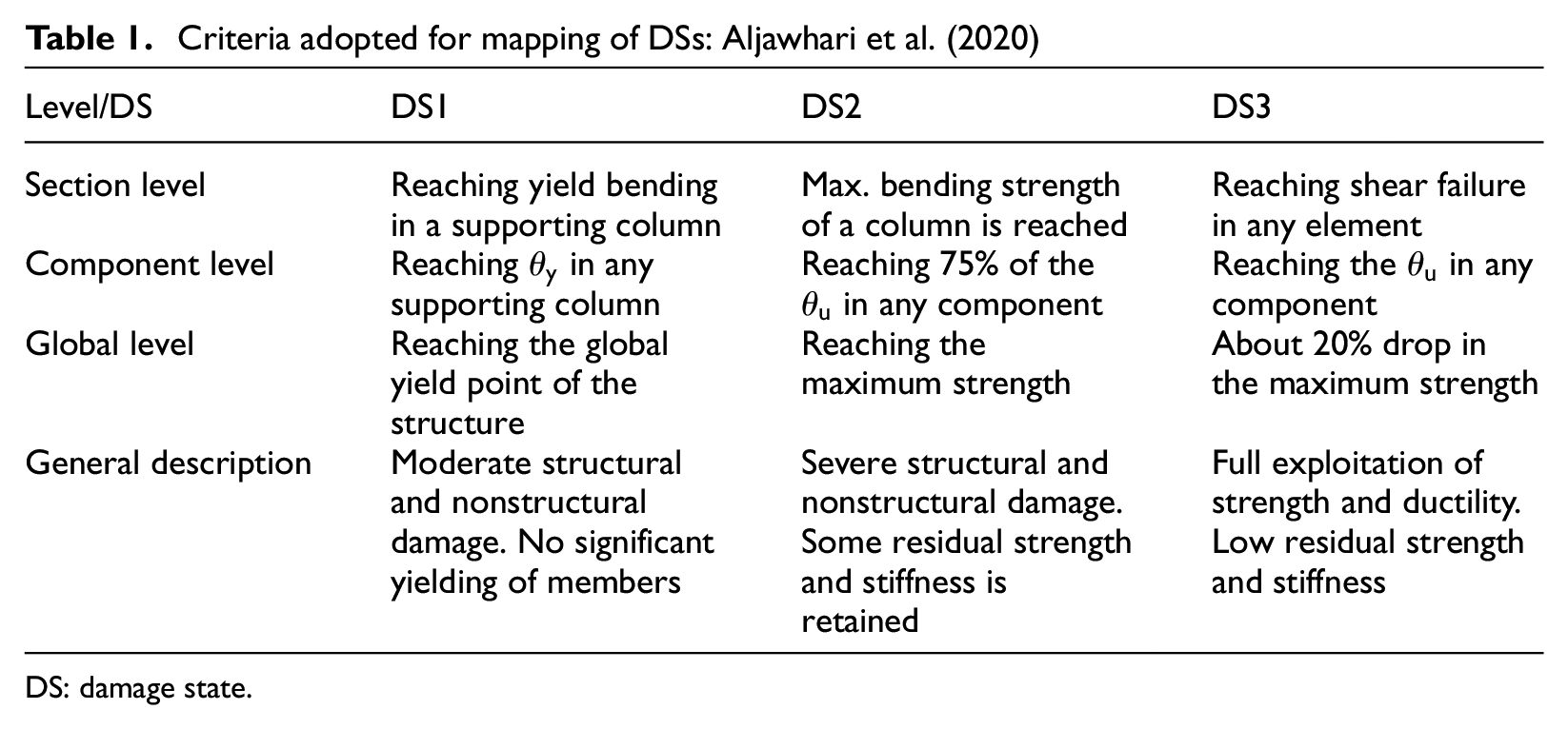
DS: damage state.
The three selected DSs are defined as follows: DS1 reflects moderate damage levels; DS2 represents significant damage (SD); and DS3 accounts for near-collapse conditions. Buildings experiencing DS2 and DS3 should meet the life safety and collapse-prevention PLs, respectively. A more detailed description of each DS is provided in Table 1. Since the infills are not modeled explicitly, the defined DSs do not account for the initial infill damage. However, it is possible to indirectly tackle this issue by using predefined MIDR thresholds existing in different codes/standards that account for such damage (e.g. 0.5%). Lastly, it should be noted that the analytical formulation of
Performance-targeted retrofit design
In this study, a large number of retrofit configurations (realizations) with varying performance are developed to demonstrate the linear trend between
For the sake of simplicity, the same hazard level is used for all performance objectives, which is the one associated with life safety, that is, corresponding to a 475-year mean return period (e.g. EN 1998-3, 2005). The seismic demand corresponding to this hazard level, which is used to design/assess the different retrofitted cases developed in this study, is characterized by a Type-1 response spectrum as per Eurocode 8 (EN 1998-1, 2004). This spectrum is defined adopting a peak ground acceleration (PGA) of 0.30 g and a ground type C to account for high seismicity conditions. Such a code-based demand is adopted for convenience and practicality; however, analysts can use any other demand form. A summary of the adopted performance objectives is provided in Table 2. Some performance objectives, other than those listed in Table 2, might require using different hazard levels with return periods lower than 475 years (e.g. operational performance objective), but they are outside of the scope of this article.
Selected performance objectives for seismic retrofit
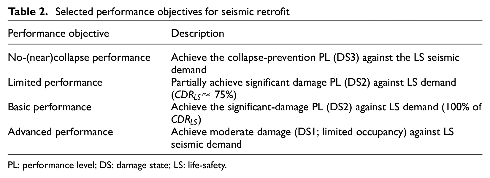
PL: performance level; DS: damage state; LS: life-safety.
It should be noted that the 475-year hazard level, introduced above, is selected because it is the most relevant and widely used one for the design/assessment of building structures, especially in Europe—and for which hazard maps/curves are (generally) readily available. It is interesting to note that, for US-based buildings, the same hazard level existed in FEMA 356 (Federal Emergency Management Agency (FEMA), 2000). However, other hazard levels are currently implemented in the most recent standards, particularly ASCE/SEI 41-17 (2017), depending on the performance objective (e.g. 225- and 975-year hazard level for the basic performance objective).
Nonlinear-modeling strategies
The nonlinear response of the case-study building is simulated by developing 2D numerical models via OpenSees (McKenna, 2011). Structural components are modeled as beam–column elements with finite-length plastic hinges to simulate the nonlinear flexural response, which is defined by performing moment–curvature analysis following Priestley et al. (2007) and Karthik and Mander (2011). The hysteretic parameters and post-capping degrading response for the moment–curvature are based on O’Reilly and Sullivan (2019). Additional shear springs are added in series to the beam–column elements to account for potential shear failure modes, as shown in Figure 7a. The backbone curve parameters for the shear response are calculated following Mergos and Kappos (2012), Sezen and Moehle (2004), and Zimos et al. (2015).
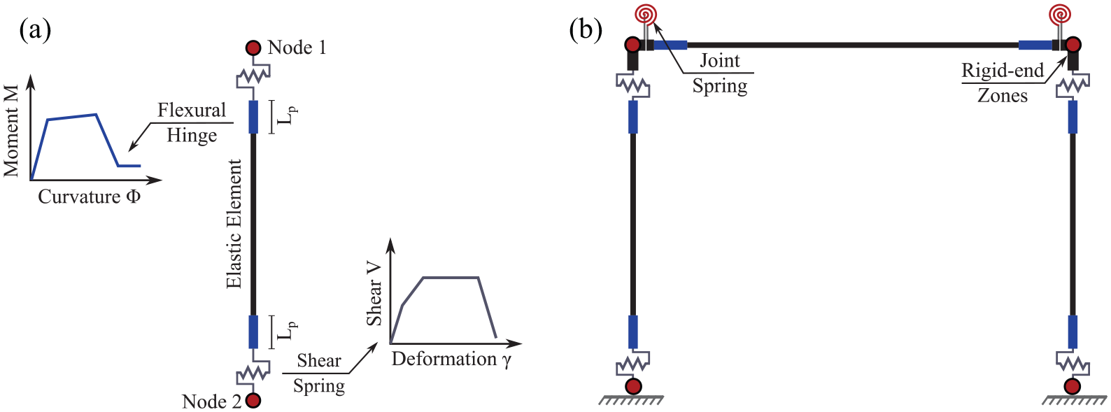
(a) Modeling strategy for column elements and (b) modeling of a frame configuration.
As stated earlier, joints in older Italian RC frames lack transverse reinforcement and use smooth bars with end-hooks, mainly in external ones (e.g. Calvi et al., 2002a, 2002b; Pampanin et al., 2002). Therefore, the early failure of such joints leads the building to develop a brittle failure mechanism. Thus, an additional spring is added in each beam–column joint zone, as indicated by Figure 7b. The parameters of the nonlinear material used for joints are defined according to O’Reilly and Sullivan (2019); a mechanics-based approach introduced in many other studies (e.g. Pampanin et al., 2003; Priestley, 1997).
It is acknowledged that the response of RC frames in Italy (and the Mediterranean region) can be considerably influenced by the presence of infills. However, they are not considered explicitly in the adopted modeling strategy. Despite such a limitation, disregarding infills remains a very popular simplification in the design practice for new structures and existing ones if they need retrofit intervention. Nevertheless, it might be necessary to consider infills in fragility analyses, at least to confirm that the fragility is reduced (right-shifting of fragility relationships) or to investigate the effects of infills on the lateral sway mechanism of retrofitted buildings. Furthermore, considering infills becomes essential if higher accuracy is needed, particularly when evaluating risk-related decision variables such as seismic losses. This is because the infill damage represents the major contributor to such losses, especially at low-intensity levels of ground shaking (e.g. Cardone and Perrone, 2015; De Risi et al., 2018; Del Gaudio et al., 2019; Sassun et al., 2016).
To account for the FRP effects on columns, the moment–curvature relationship is modified considering the confinement provided by this technique. This is achieved by first assuming that the entire column’s cross section is confined, rather than the core only, since FRP layers are wrapped around the external perimeter of the column. Next, the confinement pressure (
It should also be noted that the unique failure modes pertaining to FRP, such as debonding and fracture mechanisms, are not explicitly modeled, assuming the FRP retrofit is designed and installed appropriately so that the concrete and reinforcement will govern the softening behavior of the elements at high levels of deformation (e.g. Harrington and Liel, 2020, 2021). Steel jacketing is treated similarly to FRP. The value of
Fragility relationships and ground-motion record selection
Retrofit can lead to a significant improvement in fragility relationships, which describe the conditional probability of exceeding different structure-specific DSs over a range of IM levels, that is,

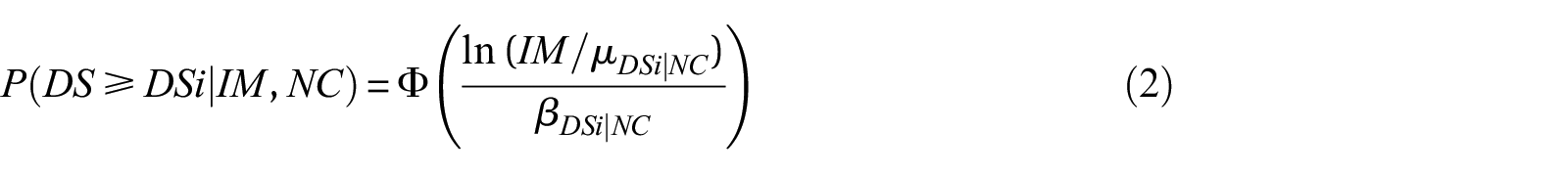
where

The records used for NLTHA are selected from the SIMBAD (Selected Input Motionsfor Displacement-based Assessment and Design) database developed by Smerzini et al. (2014), which includes 467 three-component records of shallow crustal earthquakes with magnitudes from 5 to 7.3 and epicentral distances less than 30 km (Smerzini et al., 2014). Only 150 records are selected following the criteria defined in Gentile and Galasso (2021b) and Gentile et al. (2019) to reduce computational efforts yet maintain the engineering significance of analysis. Specifically, all ground motions are ranked based on their PGA obtained as the geometric mean of the two horizontal components. The horizontal component with the highest PGA is kept for each ground motion, then the 150 records with the highest rank are selected. Such a record-selection procedure is compatible with the adopted analysis approach, that is, cloud analysis. This approach, among others such as the MSA, is more appropriate for risk assessment of building portfolios, especially when coupled with optimal IMs, as done in this study. This is related to the fact that it does not require site- and building-specific hazard-consistent record selection; thus, the same record set can be used to perform NLTHAs for an entire building portfolio.
The implemented IM is the geometric mean of the 5%-damped spectral acceleration over a specific range of periods
Results and discussion
Performance assessment for the as-built structure
To understand the response and failure mechanism of the as-built case-study structure, an initial assessment is carried out using pushover analysis to identify the DS thresholds and then apply the CSM to evaluate the
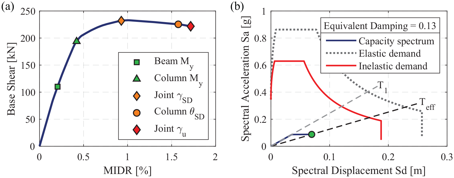
As-built case: (a) pushover curve and damage observations and (b) capacity and demand spectra.
MIDR thresholds for different DSs derived from pushover analysis
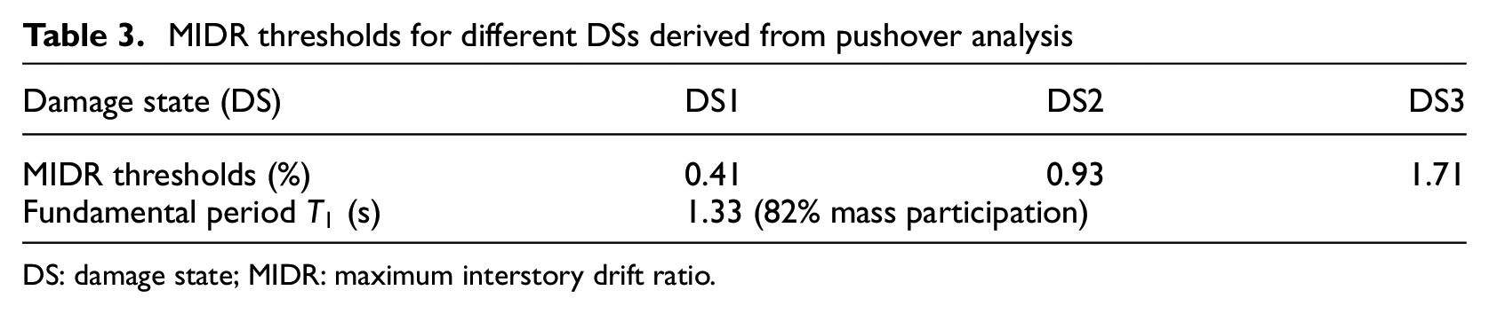
DS: damage state; MIDR: maximum interstory drift ratio.
It can be observed in Figure 8a that both DS2 and DS3 are controlled by the limit states of the joints, which take place before those of the columns. It is also noticed that the beams do not reach their
Figure 8b illustrates the idealized capacity spectrum of the equivalent SDoF system and the demand spectrum, both elastic and inelastic, plotted in the ADRS space. Applying the CSM, it is found that the inelastic demand spectrum (for a damping level corresponding to the LS displacement) significantly exceeds the capacity of the as-built structure. In other words, the capacity spectrum cannot intersect the inelastic demand spectrum, thus indicating a
Designed retrofitting solutions
The as-built structure is retrofitted aiming at selected performance objectives (see Table 2) to study the
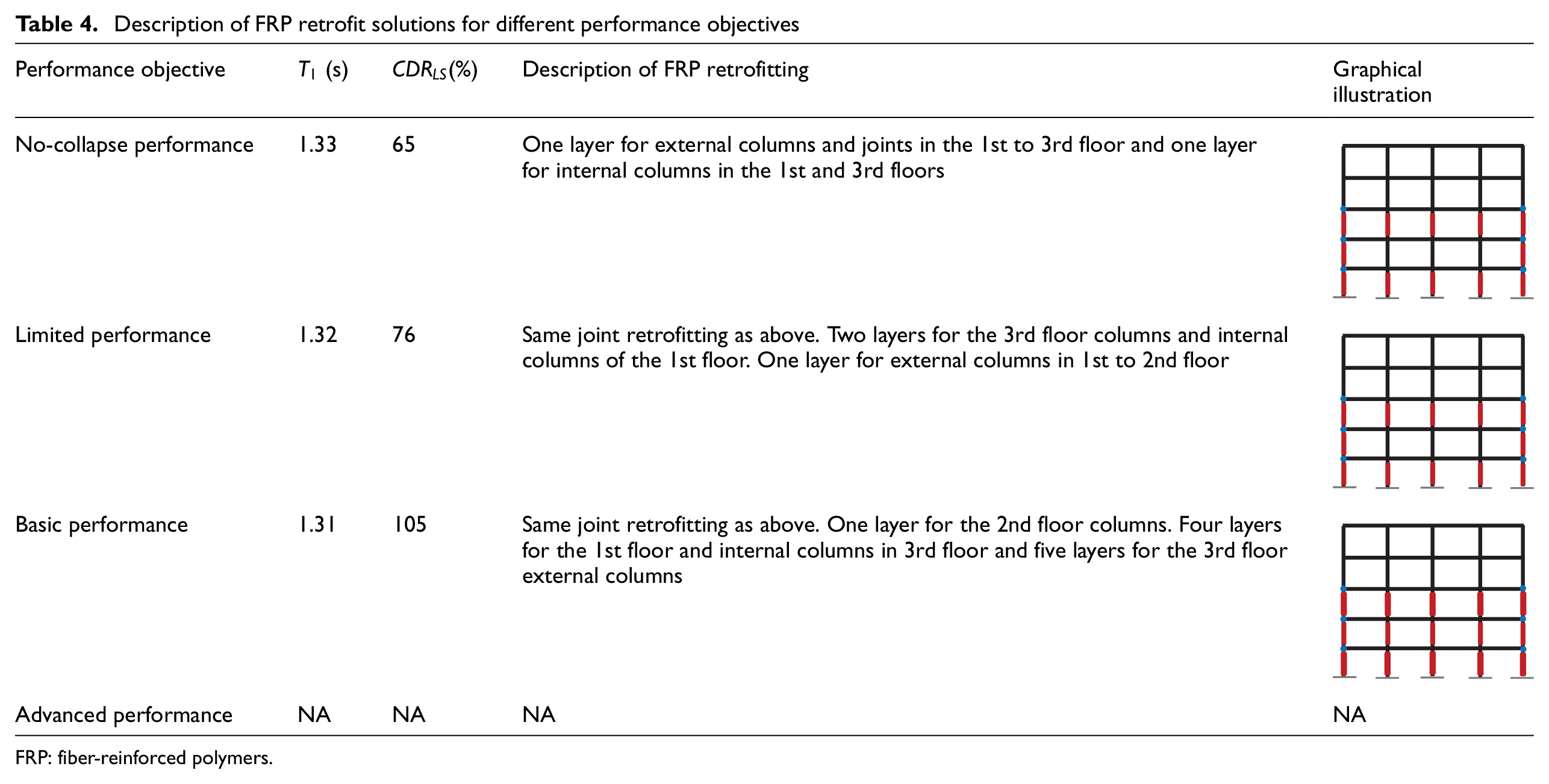
Table 4 shows the details, layout, and number of retrofitted elements using FRP for all performance objectives. For brevity, only one retrofitted case is described for each performance objective, particularly the one satisfying the objective with the minimum possible amount of intervention. Table 4 demonstrates that the advanced performance objective could not be achieved using the FRP wrapping because it only improves ductility through confinement and increases shear strength. Its contribution to the lateral strength and stiffness is minimal (less than 10% in this study). However, enhancing these parameters is essential with respect to moderate damage PL (or DS1) as the columns will not yield quickly, especially at low IM levels. It should be noted that the maximum value of
Description of FRP retrofit solutions for different performance objectives
FRP: fiber-reinforced polymers.
Table 5 provides similar information about the cases retrofitted with steel jacketing. It was possible to generate many cases of retrofitted buildings with larger
Description of steel jacketing retrofit solutions for different performance objectives
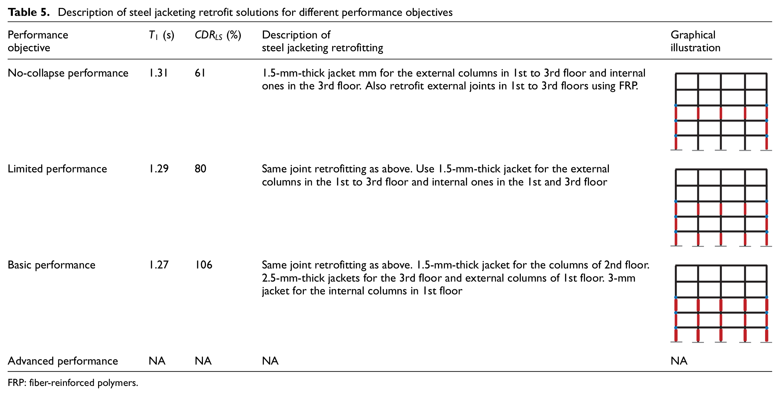
FRP: fiber-reinforced polymers.
Finally, a summary of the case studies with RC jacketing is provided in Table 6, which shows that the advanced performance objective is achieved, unlike FRP and steel jacketing. This is because the RC jacketing provides a significant overall enhancement for the stiffness and strength, both shear and flexural, and improves the ductility through confinement. These features can also shift the building mechanism from local (e.g. soft-story) to global, that is, beam-sway. Therefore, the (frame-level) MIDR threshold of DS1 becomes much higher, and the retrofitted structure will not be easily subjected to yielding and moderate damages, especially at low IM levels. Nevertheless, as illustrated in Table 6, achieving the advanced PL requires retrofitting the entire columns of the case-study building, resulting in a global retrofit intervention rather than local, which might be expensive and technically challenging.
Description of RC jacketing retrofit solutions for different performance objectives
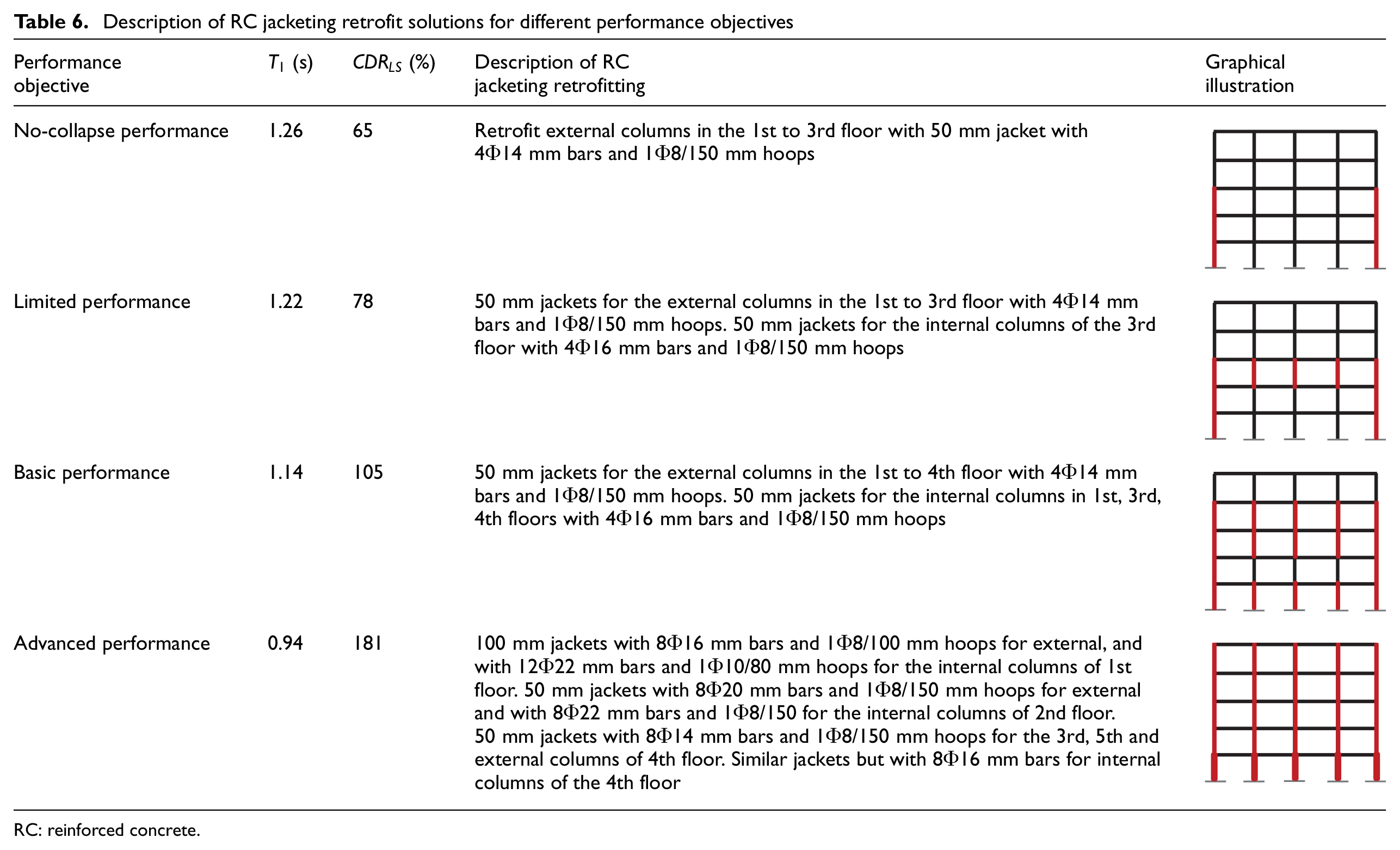
RC: reinforced concrete.
To provide more illustration, Figure 9 depicts the new performance points representing the intersection between demand and capacity spectra (obtained using the CSM) for a sample of retrofitted case-study structures for the three retrofit techniques considered in the current study. The corresponding values of
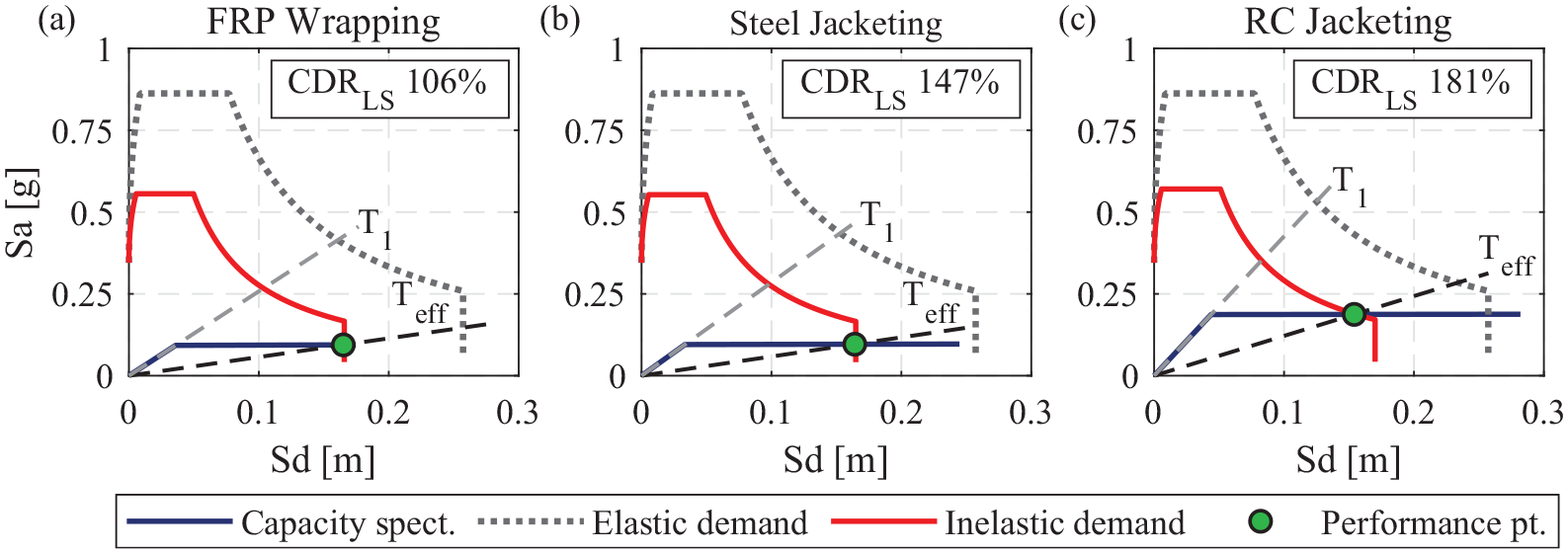
Capacity and demand spectra: (a) FRP wrapping, (b) steel jacketing, and (c) RC jacketing.
Seismic fragility assessment
Upon developing non-linear models for both the as-built and retrofitted case studies, NLTHAs are performed using the selected set of ground-motion records in order to assess the seismic performance and derive the corresponding fragility relationships. Figure 10a shows the IM versus EDP cloud and the fitted PSDM, demonstrating that the as-built structure remained undamaged (ND) in less than 20% of the analysis cases. In contrast, approximately 60% of the cases are characterized by high damage conditions (i.e. DS2 and DS3). Such a poor seismic performance is also reflected in the fragility relationships in Figure 10b, showing that the building is expected to experience high DSs, even at a low IM level. Fragility assessment is then carried out considering the retrofitted case studies defined earlier. The fragility relationships for the as-built and retrofitted cases are reported in Figure 11 as evidence of the substantial impact of retrofitting. For each retrofit technique, the fragility relationships for only one retrofitted case are illustrated for each performance objective, particularly those that satisfied each objective with minimal intervention. The resulting fragility parameters, including median
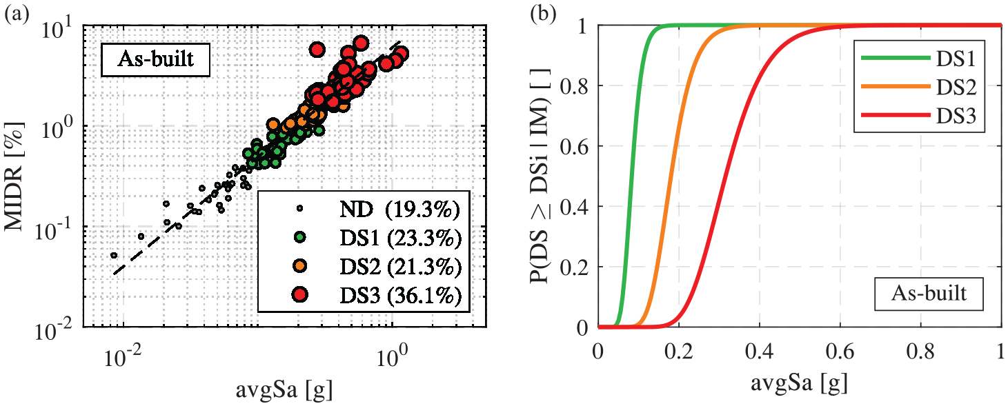
(a) IM versus EDP cloud and (b) fragility relationships for the as-built structure.
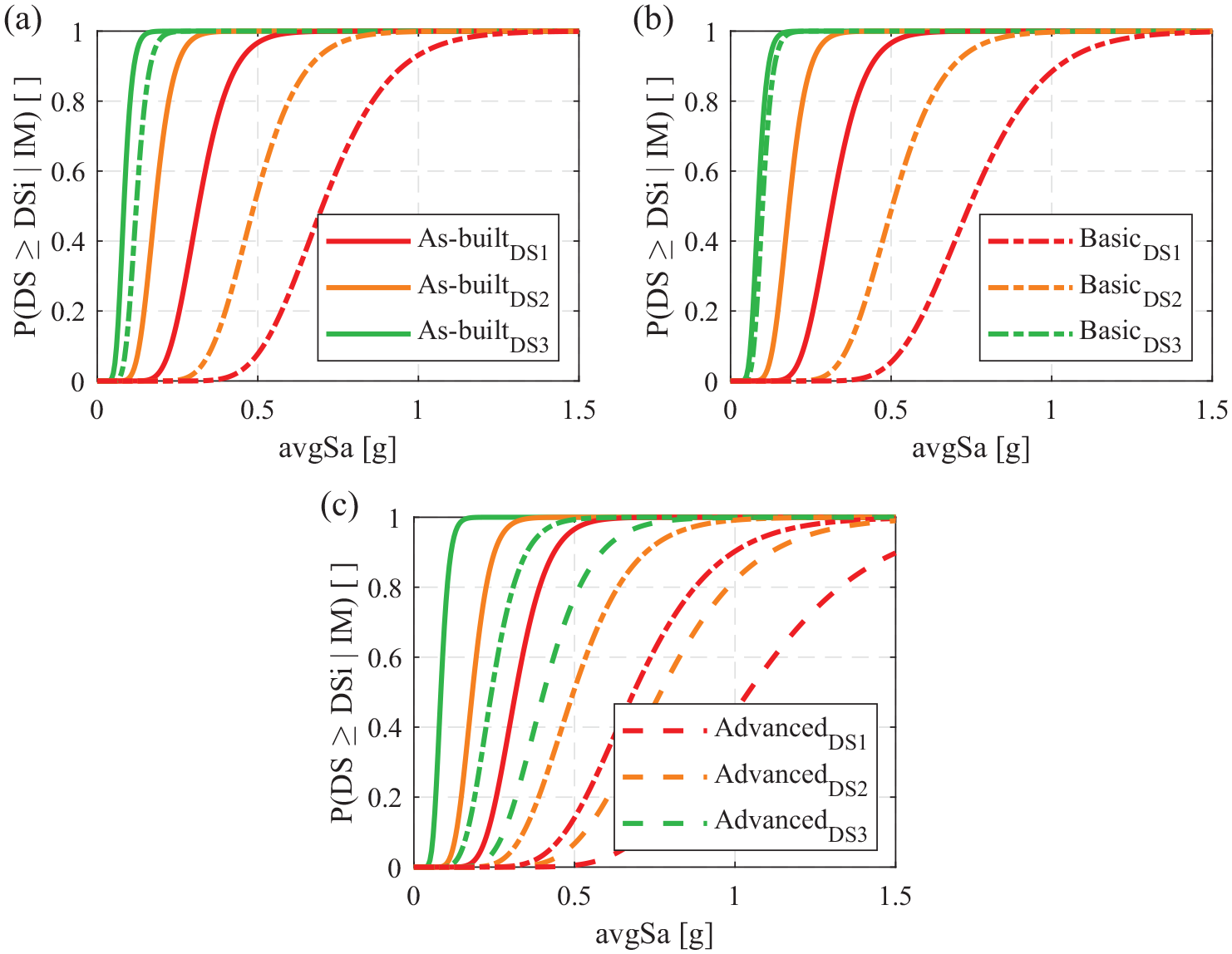
Fragility relationships for different performance objectives considering (a) FRP wrapping,(b) steel jacketing, and (c) RC jacketing.
Fragility parameters of the as-built and retrofitted cases for different performance objectives
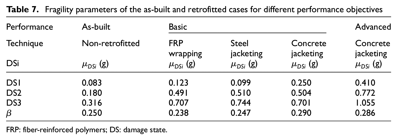
FRP: fiber-reinforced polymers; DS: damage state.
Figure 11 reveals a significant improvement in the fragility relationships of DS2 and DS3 when the frames are retrofitted until satisfying the basic performance objective (
On the contrary, improving the DS1 fragility relationship requires enhancing both lateral strength and stiffness to control the sway mechanism of the building and make it more resistant against developing moderate damages due to early yielding. However, the contribution of steel jacketing to the lateral strength and stiffness is minor compared with RC jacketing, whereas the contribution of FRP is almost negligible. In contrast, RC jacketing can change the mechanism to a full beam-sway one. It also provides a significant overall improvement for all the above parameters, which resulted in a considerable shift in the DS1 fragility relationship illustrated in Figure 11c. Furthermore, the advanced performance objective could be achieved using RC jacketing, which caused a considerable shift in the fragility relationships of the three DSs.
It is important to remember that the same period range is adopted to quantify avgSa for the as-built and retrofitted cases to allow fragility comparison. This period range is based on T1 of the as-built case, which is the largest. It is understood that T1 might notably change upon retrofitting due to stiffness and/or mass variations. However, the retrofitted cases are more ductile than the as-built ones, and they can experience period elongation of up to 3 T1 (ASCE/SEI 7-16, 2017; Baker and Cornell, 2006). Also, the change in T1 for the majority of the retrofitted cases is not substantial. This makes the selected period range appropriate for derived the fragility curves. It is also worth noting that the variation in
Correlation between
and fragility medians
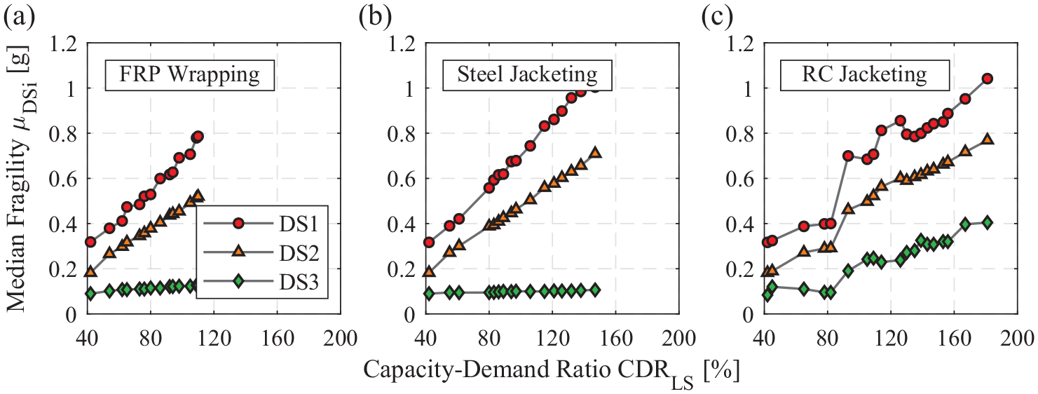
The proposed fragility-oriented approach for the retrofit design relies on the assumption that the
Variation of
Variation of
In contrast, the overall increase in
The clear trends between
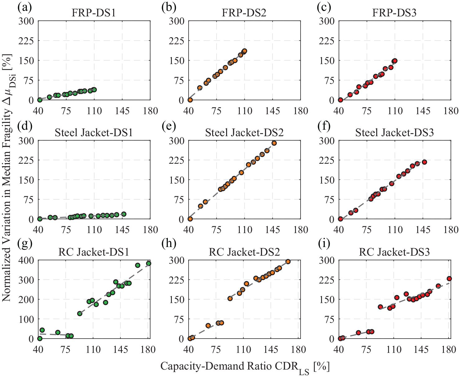
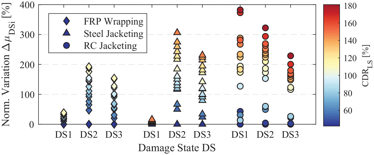
Correlation between the normalized variation of
The numerical form of the models is provided in Table 8, knowing that the initial
Mathematical expressions developed for
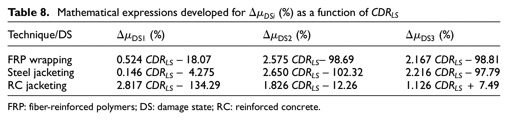
FRP: fiber-reinforced polymers; DS: damage state; RC: reinforced concrete.
It is worth mentioning that the results obtained by the proposed models are limited by the uncertainties associated with the modeling assumptions, material properties, geometry, layout, and so on. Therefore, additional research is required to generalize such models (expressions) to other structural typologies with different failure mechanisms and geometric and material properties. Those, in turn, can be adopted to analyze and/or design scenario-based retrofit implementation plans at a portfolio level through a regional seismic risk model (e.g. Silva et al., 2018). This is beyond the scope of this study and requires further investigation.
An illustrative application of the fragility-oriented approach for retrofit design
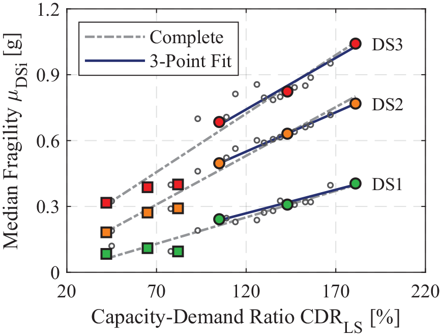
The proposed fragility-oriented approach for the retrofit design takes advantage of the pseudo-linear relationship between the
It is worth recalling that if the retrofit intervention leads to a significant shift in the sway mechanism (e.g. from soft-story to beam-sway), the relationship between
Linear models of
It is interesting to note in Figure 15 that the models fitted by using the three-point set upon the mechanism shift are almost identical to those fitted using the entire point set, which incorporates all the different mechanisms simultaneously. This is attributed to the fact that most of the points in the full set constitute the retrofitted structures after the mechanism shift, so they dominated the fitted models. However, for practical application of the fragility-oriented approach, only three points are needed for efficiency. Therefore, special attention must be given to the failure mechanism for each selected point. On the contrary, the FRP wrapping and steel jacketing techniques could not entirely prevent column hinging; hence, no sudden jump was recorded in the
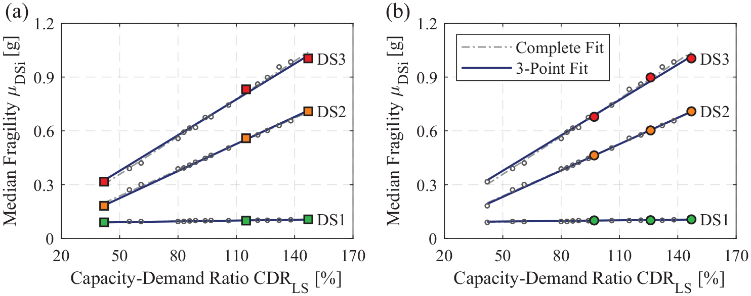
Comparison between the linear models of
Conclusion
This study proposed a fragility-oriented approach for seismic retrofit design. This approach relies on the mapping between the displacement-based ratio of capacity to life-safety demand
The application of the proposed retrofit design approach only requires defining three points in the
Although the illustrative analysis in this article involved a single case study, the empirical data agrees well with the general mechanics-based discussion on the
Footnotes
Acknowledgements
The authors are very grateful to Dr Gerard O’Reilly (IUSS Pavia) and Dr Eyitayo Opabola (UCL) for their constructive and insightful comments that improved the quality of this study.
Declaration of conflicting interests
The author(s) declared no potential conflicts of interest with respect to the research, authorship, and/or publication of this article.
Funding
The author(s) disclosed receipt of the following financial support for the research, authorship, and/or publication of this article: This study has received funding from project “Dipartimenti di Eccellenza,” funded by the Italian Ministry of Education, University and Research at IUSS Pavia. R.G. received additional funding from the European Union’s Horizon 2020 research and innovation program under grant agreement no. 843794. (Marie Skłodowska-Curie Research Grants Scheme MSCA-IF-2018: MULTIRES, MULTI-level framework to enhance seismic RESilience of RC buildings.)