
Abstract
As a result of rapid urbanization worldwide, there is an increasing demand for high-rise buildings, creating an acute need for more resilient tall structures, especially in regions of high seismicity. One of the main challenges facing design engineers is that buildings become increasingly susceptible to higher-mode effects as they become taller. Although current design practices typically achieve life-safety and collapse-prevention during major earthquake events, there is often extensive structural and non-structural damage, in great part exacerbated by the contribution of higher-mode responses. This article proposes a novel system involving a flexure and shear yielding base-mechanism, designed to limit both the first mode and higher-mode responses of a 42-story benchmark structure. These concepts only make use of well-defined buckling restrained steel braces, which have been extensively tested over many decades now and are currently implemented widely in buildings, to achieve the desired shear and flexural base yielding mechanisms. Nonlinear three-dimensional (3D) models developed in ABAQUS were used to validate key elements while models of the benchmark structure and base-mechanism were developed in ETABS to perform Nonlinear Time-History Analyses (NLTHA) for three hazard levels to investigate the global seismic response of the proposed system. Improvements among key seismic response parameters are observed at all hazard levels. By concentrating inelastic demands in the dedicated base steel yielding braces in the proposed system, quick inspection and potential repair after a major earthquake can be achieved with reduced disruptions to the use and operation of the building above.
Keywords
Introduction
The increasing population density in urban areas has sparked a surge in high-rise construction to accommodate the growing number of city residents worldwide. In 2019, 126 buildings were completed with a height of 200 m or taller (Council on Tall Buildings and Urban Habitat (CTBUH), 2019). As many densely populated cities are in high-seismicity regions, novel design options for high-rise structures that are resilient during major earthquake events are needed. One of the most common methods of high-rise construction has been reinforced concrete (RC) walls used as lateral systems that exhibit high flexural and torsional stiffness (Christopoulos and Zhong, 2022). During an earthquake, these structures dissipate seismic energy and limit seismic demands by relying mainly on a designated plastic hinging mechanism at their bases. Although such design methods effectively limit the first mode response of these structures, they are still susceptible to higher modes of vibrations despite the formation of plastic hinging mechanisms at the base, while forces and bending moments continue to increase along the height of these structures due to the excitation of higher modes — a phenomenon often referred to as higher-mode effects (Blakeley et al., 1975; Christopoulos and Zhong, 2022; Fatemi et al., 2020; Rutenberg, 2013, among others). Since higher modes of vibration tend to contribute more to the dynamic response of structures with longer periods and increased ductility demands (Rutenberg, 2013), the amplification of demands due to higher-mode effects has been identified as one of the critical challenges for the seismic design of high-rise RC-wall structures. While experimental studies investigating higher-mode effects are limited, available studies have shown amplifications in base-shear demands attributable to significant higher modes of vibration not controlled by the designated plastic hinging mechanism at the base (Eberhard and Sozen, 1993; Ghorbanirenani et al., 2012; Panagiotou et al., 2011, among others). In addition, extensive analytical studies have been conducted since the 1940s that advanced the understanding of higher-mode effects on the amplification of seismic demands in tall and slender RC-wall structures (Adebar et al., 2014; Blakeley et al., 1975; Panagiotou and Restrepo, 2009, among others). Comprehensive reviews of higher-mode effects on slender RC-wall structures can be found in Rutenberg (2013) and more recently in Christopoulos and Zhong (2022).
Although RC core systems have typically achieved life-safety during major seismic events, excessive structural and non-structural damage in past earthquakes has led to service disruptions, extensive repairs, and even to complete demolition (e.g. Elwood, 2013; Moehle, 2010; Pinkham, 1973). A study by the Pacific Earthquake Engineering Research Center (PEER, 2011) reported that in general, RC core wall buildings have the highest mean annual repair costs, compared to core wall/moment frame dual systems and buckling-restrained braced frame systems. For example, the M8.8 earthquake that struck Chile in 2010 resulted in 40 severely damaged shear wall buildings, which required extensive repairs or demolition, and one complete collapse (Jünemann et al., 2016). A similar situation was observed in Christchurch, New Zealand after the M7.1 earthquake and M6.2 aftershocks in 2010 and 2011. The collapse of two mid-size RC shear wall buildings accounted for 135 of the total 182 casualties (Kam et al., 2011). Of all shear wall buildings in the city, over half were deemed of restricted access or worse, with many requiring demolition (Kam et al., 2011). Many of these RC core wall buildings experienced significant damage due to poor detailing of their ductile mechanisms. While poor detailing was identified as the main cause of this poor performance, there has been an increased recognition among researchers and practitioners of the effect of higher-mode effects on the response and performance of typical RC core wall buildings. This has led to an increase in interest recently in developing high-performance systems that can enhance the seismic resilience of these structures without relying solely on the ductile detailing of designated RC components.
Previously proposed high-performance systems
Several high-performance systems have been proposed to improve the seismic response of high-rise structures, with a primary aim to limit the damage. To reduce excessive damage in the base plastic hinge region due to the inelastic response of RC, pin-supported walls (Alavi and Krawinkler, 2004), or base-rocking walls, were proposed (Kurama et al., 1999; Stanton et al., 1993; Zhong and Christopoulos, 2021, among others) and have been used in the seismic design and retrofit of several buildings in Japan (Qu et al., 2012; Wada et al., 2011) and the United States (Mar, 2010; Stevenson et al., 2008), which only prevented damage at the base of the walls while excessive demands above the base were not controlled. MacKay-Lyons et al. (2018) explored the use of viscoelastic dampers in place of traditional concrete coupling beams. While coupling beam damage was greatly reduced with this method, damage to the wall bases was not eliminated. A dual plastic hinge concept was investigated by Panagiotou and Restrepo (2009), in which plastic hinging was designed to occur at the base of the wall and at mid-height. This method reduced the bending moment envelope along the wall height but did not significantly impact shear forces. Recent advancements have made use of rocking systems to achieve an inelastic response that limits base moments without inducing structural damage. Rocking mechanisms eliminate material nonlinearity and are self-centering but are still susceptible to higher-mode effects and can therefore experience high shear force amplifications along the height of the structure (Wiebe et al., 2013a). Challenges in controlling both bending moments and shear forces in tall buildings have resulted in a recent push for uncoupled flexure and shear systems. An uncoupled system was developed for rocking steel frames by Wiebe et al. (2013a), which involves a multiple-rocking-section design with a nonlinear brace at the base to control shear. This system was shown both experimentally and numerically to reduce moments, shears, and accelerations when compared to the traditional braced frame or rocking frame structures (Wiebe et al., 2013a, 2013b). The new San Francisco Air Traffic Control Tower was constructed with a self-centering flexural rocking mechanism combined with force-limiting braces at the base level (Sabelli et al., 2017). Self-centering was achieved through vertical post-tensioned (PT) tendons while horizontal buckling-restrained braces (BRBs) provided a force-limiting backstay mechanism at the base (Sabelli et al., 2017; SEAOC, 2016). Tong and Christopoulos (2020) developed a concept for achieving uncoupled rocking flexure and shear mechanisms for a high-rise core wall system. This high-performance system incorporates a rocking flexural mechanism through rocking-rolling mega-columns located below the concrete core, which caps the base overturning moment through rocking of the core wall above the mega-columns while providing negligible lateral shear resistance. The lateral shear resistance is provided by a designated shear mechanism comprised of buckling-restrained braced frames located outside the core, which is connected to the core through gear teeth that transmit only horizontal forces without impeding the vertical uplift caused by the rocking response, thus uncoupling the flexural and shear mechanisms at the base. The rocker uplifts from the mega-columns that carry no shear forces (i.e. leaning columns). Nonlinear shear fuses outside of the core area in the form of braced frames are activated by shear transmitters (i.e. gear teeth) that do not interact with the rocking response. While the authors (Tong and Christopoulos, 2020) reported an overall enhanced seismic performance according to a numerical case study on a high-rise building equipped with such a system at the base, the practical implementation of such a system still presents several challenges in the constructability and cost-effectiveness of the system with complex engineering, detailing, and elevated costs.
Proposed concept
To improve on the concept developed by Tong and Christopoulos (2020), this article proposes a high-performance system that achieves a similar uncoupled shear and moment base mechanism while utilizing only pre-qualified, commercially available steel components. In this proposed system, BRBs were selected as the main ductile elements providing both flexural and shear yielding at the base of high-rise buildings. BRBs are extensively tested, standardized, and codified products commonly used for multiple seismic design applications with high levels of ductility and energy dissipation without strength degradation (Kersting et al., 2015). Through flexure and shear yielding of the base-mechanism, moment and shear demands transferred to the superstructure are both limited, thereby reducing the inelastic demands on the concrete walls and the coupling beams. Figure 1 schematically illustrates the behavior of the system proposed in this article. As shown in Figure 1, the proposed system utilizes vertically-placed, pin-connected BRBs to control the overturning moment response at the structure base and carry the gravity loads that are resisted by the flexural-yielding mechanism, while shear forces at the structure base are mainly transmitted to the exterior frames through the leaning column action of the vertically-placed BRBs. The exterior frames then control the shear response at the base through the yielding of the diagonally-placed BRBs within the frames.
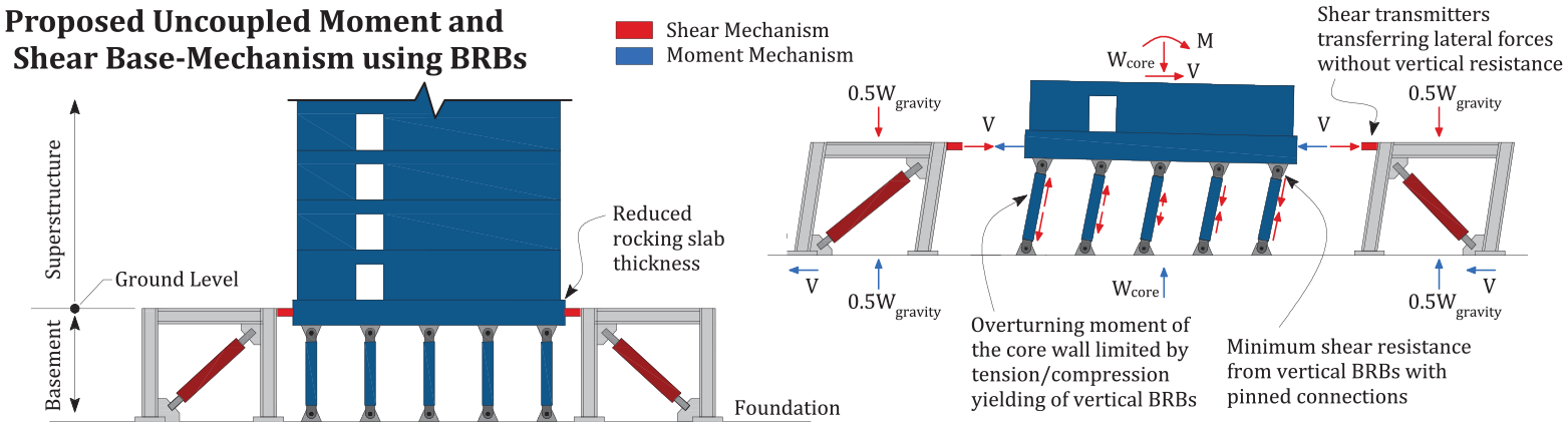
Proposed steel flexure and shear yielding base-mechanism using BRBs.
Figure 2 provides a detailed illustration of the proposed system as part of a high-rise building used in the design case study that is included in this article. As shown in the three-dimensional (3D) exploded view of the overall system in Figure 2, high-capacity BRBs are installed as vertically oriented members directly below the core walls, to control the overall flexural strength at the core-wall base while carrying the gravity loads of the core wall. Under a predetermined level of base overturning moment, these vertical BRBs yield axially in tension and compression, capping the base moment and reducing the first mode response of the structure. In addition, these vertical BRBs are pin connected at each end, allowing them to act primarily as axially loaded members and behave as leaning columns under lateral loading. As such, they do not provide lateral shear resistance to the system, but rather produce additional lateral loading due to the P-delta effects that are resisted by the shear mechanism. Therefore, the total lateral resistance of the proposed system is entirely controlled by the shear mechanism alone. To transfer gravity loads from the concrete core to the base-mechanism, a PT slab and girders system is used. Outside of the core is a podium slab, below which the gravity columns and the shear mechanism are located. Lateral shear capacity is provided by two sets of four-bay braced frames in each direction at the base. Axial yielding of the diagonal braces limits the base shear, controlling higher modes of vibration in the superstructure. The exterior shear mechanism and interior flexural mechanism are uncoupled by using diaphragm force transmitters which transfer shear forces only, without interfering with the flexural response of the base. This intended behavior is achieved through replaceable flexural yielding steel plates. By uncoupling the systems, the flexure and shear capacity can be sized independently to meet targeted strength requirements for each yielding mechanism. Discussions on key components of the proposed system shown in Figure 2 are provided in detail in the design case study presented in the following sections of this article.
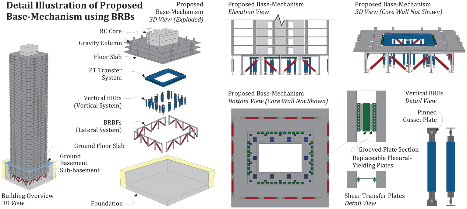
Detailed illustration of the proposed system as part of a high-rise building.
Benchmark structure
The proposed high-performance system was designed and detailed for a 42-story benchmark structure located in Los Angeles, California. This building was designed and analyzed as part of the Tall Buildings Initiative by PEER (2011) and consists of an RC coupled core as the lateral force-resisting system with slabs on columns making up the gravity system. Performance-based design criteria as per the Los Angeles Tall Buildings Structural Design Council were followed for the structural design (PEER, 2011). An isometric view of the benchmark structure, a plan view, and the coupling beam layout are presented in Figure 3. To achieve linear-elastic behavior of the superstructure for all hazard levels, the base plastic hinging mechanism of the benchmark structure was designed to yield at approximately the base moments and shears obtained under Service-Level Earthquake (SLE) events with 25 years mean recurrence interval as defined by PEER (2011). As part of the preliminary model validation, the SLE-level base-shear and moment demands obtained from a response spectrum analysis conducted using ETABS 2018 (ETABS) (Computers and Structures Inc. (CSI), 2019) were 20.7 MN and 879 MN m in the east-west direction, respectively. In the north-south direction, the capacities were 24.1 MN and 1254 MN m (Kent, 2021). These values are within 10% of the SLE results reported by PEER (2011).
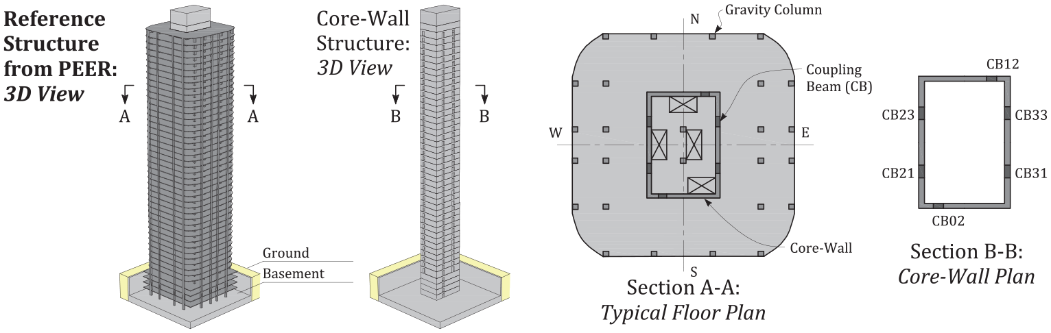
Benchmark high-rise structure.
Detailed design of components
Buckling-restrained braces
Directly below the walls, 40 BRBs, each with a nominal yield strength of 8 MN, are oriented vertically and spaced in 10 bundles of four braces, as shown in Figure 2. BRBs of this capacity have been used in existing structures, such as the Osaka International Conference Center (Hikone et al., 2001). The same total vertical capacity can be achieved with multiple other combinations of BRBs, including smaller braces positioned in different configurations. All gravity loads from the core are transferred to these braces through PT girders. Outside of the core footprint, an additional 18 braces are distributed in a 16 m × 20 m perimeter connected by a PT slab. These braces are 6 MN in capacity each and carry no gravity loads. The sizing and spacing of these braces were selected to achieve a simple transfer of gravity loads from the core down to the foundations and to achieve the design minimum base overturning moment strengths in each direction — approximately 900 MN m in the east-west direction and 1300 MN m in the north-south direction. In the elastic range, a similar moment-drift response to that of a conventional fixed-base design is achieved. In the nonlinear range, yielding of the braces produces overturning moments (OTMs) that are approximately 10% less than the minimum base overturning moment strengths of the benchmark structure, ensuring that the base overturning moment applied to the core walls of the proposed system does not exceed that of the benchmark structure (Kent, 2021). For the shear mechanism, details on how the BRB capacities were selected are presented later in this paper through a parametric study.
Post-tensioned slab and girders
A PT girder and slab system is proposed to transfer loads from the core to the base-mechanism. The proposed system consists of 80 MPa concrete and makes use of low relaxation seven-wire post-tensioning strands. Both the girders and the slab were designed to remain elastic under sustained loading and strength-designed for maximum considered earthquake (MCE) loading. Girder dimensions were 1000 mm × 2000 mm with an 800 mm deep slab with a combination of straight and parabolic tendons. Details of the pre-stressing design can be found in Kent (2021).
BRB pin connections
For the vertical BRBs to only produce axial loads and not interact with the shear-mechanism in the horizontal plane, a 3D pin connection is required at each end. The in-plane response of the pin-connected gusset plate is governed by a true-pin behavior in which brace rotations are accommodated while generating minimal forces and moments, and friction between the pin and the gusset plate provides the only rotational restraint. For the out-of-plane response, one way to achieve a nearly true-pin response is to detail the gusset plate with a plastic hinging zone similar to that typically used as part of the Special Concentrically Braced Frames (SCBFs) (Roeder et al., 2011; Zhong et al., 2020), in which plate hinging is part of the brace buckling mechanism. In SCBFs, the braces buckle under compression and place high out-of-plane rotational demands on the plate that must be accommodated while not compromising the axial load carrying capacity of the brace. With proper detailing, these connections can achieve out-of-plane rotations up to ±5.5 degrees by forming plastic hinges, which generate negligible base moments and shear forces (Kotulka, 2007; Lai and Mahin, 2013). This allows the BRB columns to primarily generate axial loads only. Alternatively, swivel connections commonly utilized in dynamic actuator and shaking table applications (e.g. MTS, 2021) can be used in lieu of conventional pinned gusset plates, which accommodate out-of-plane rotations up to ±8 degrees through a mechanical mechanism rather than a material-yielding mechanism (MTS, 2021), thus eliminating the potential accumulation of inelastic demands in these connections and further increasing the seismic resilience of the proposed system.
Replaceable flexural yielding steel plates
Uncoupling of the flexural system from the surrounding podium slab while enabling the transmission of diaphragm forces was achieved through the flexural yielding of replaceable steel plates, as illustrated in Figure 2. These plates are designed to form flexural hinges in the replaceable portion when they deform vertically as a result of the base rotation caused by the flexural yielding that occurs at the base, such that limited vertical forces are transferred from the core to the podium slab. Any moments generated by axial loading on the frames and columns are therefore negligible in comparison with the base moment generated by the vertical BRBs. As indicated in Figure 2, grooved plate sections are introduced in these replaceable plates to isolate the flexural yielding and protect the bolted connection region. Lateral forces and deformations from the core are transferred axially through the steel plates to activate the shear fuse mechanism (diagonal BRB frames). The intended force-transfer mechanism of these steel plates is similar to that of the gusset plates in the SCBFs, where axial forces are transferred through the plates and moment demands perpendicular to the plates are limited through flexural yielding of the plates (Kotulka, 2007; Lai and Mahin, 2013; Roeder et al., 2011). The proposed hinging plates are 350 MPa steel and are 11,430 mm long and 700 mm wide. At each end, bolted connections are used to connect the hinging plates to connection plates that are designed to have a factored capacity higher than the expected strength of the hinging plates and are embedded into either the PT core slab or the podium slab. Shear studs would also be included to resist tension forces developed in the plates to ensure adequate behavior. For the design case study, plates as thin as 10 mm were deemed sufficient for transferring lateral loads while forming flexural hinges at the edges, but this could be increased to 25 mm to increase the safety factor for transferring diaphragm forces without significantly impacting the overall behavior of the system.
Finite element analysis
Connection performance
Each of the articulations that were previously presented was investigated with 3D nonlinear finite element (FE) analysis using ABAQUS (Simulia, 2013). In this phase of the validation, the core walls were modeled with elastic shell elements representing the elastic stiffness of the concrete core. Gravity columns were modeled with linear-elastic truss elements, while buckling-restrained braced frames and vertical braces were modeled as nonlinear truss elements. To reduce computation time, bundled BRBs were modeled as a single element with four times the capacity and stiffness. Replaceable flexural-yielding steel plates were modeled using solid elements with an elastic-perfectly plastic material model. A bilinear hardening model was used to capture the overall BRB response using experimentally calibrated hardening parameters proposed by Wigle and Fahnestock (2010). The degree of uncoupling of the flexural mechanism was measured by conducting a pushover analysis up to 3% roof drift at a height of 100 m in the north-south direction, following previous studies conducted using other software (MacKay-Lyons et al., 2018; Tong and Christopoulos, 2020). The total base moment, including contributions from the gravity columns and braced frames, was compared to the base moment generated by the vertical braces only. At maximum drift, the increase in base overturning moment was only 7%, essentially achieving the desired uncoupled behavior. Plastic hinging was well-isolated in the grooved sections of the replaceable plates. Figure 4a shows results from the pushover analysis that was completed using ABAQUS, comparing the response of only the vertical BRBs to the total base moment. The deformed shape and stress contour of one of the replaceable flexural-yielding plates are presented in Figure 4b. A maximum flexural-yielding rotation of 4.6 degrees was obtained for these plates, which is lower than the typical out-of-plane rotation demands of up to 5.5 degrees observed in well-designed gusset plates for SCBFs (Palmer et al., 2013). Therefore, the design of these flexural-yielding plates is deemed appropriate for the design case study, and fracture due to excessive flexural rotation is not expected in these replaceable plates.
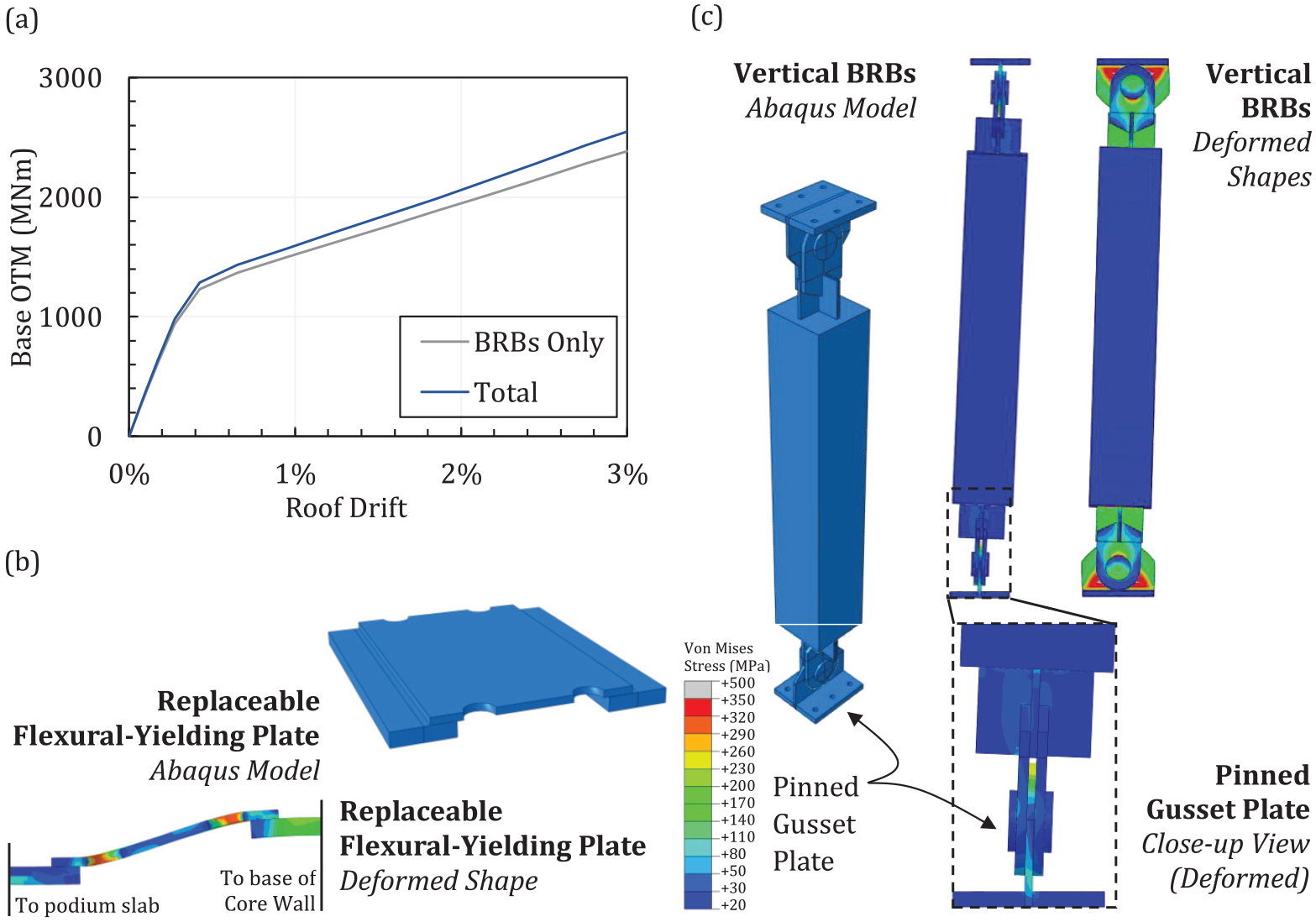
(a) Moment versus drift response, (b) replaceable flexural-yielding steel plate deformed shape, (c) gusset plate bending.
The response of a single BRB was then analyzed with a pinned gusset plate connection at each end with explicit modeling of contact interactions within the pinned connection, including the effect of friction. Details of the plate sizing and nonlinear modeling can be found in Kent (2021). Figure 4c presents the deformed shape and stress contours obtained for one BRB loaded in compression and displaced horizontally up to 2% drift (of its initial length) in both principal horizontal directions. The maximum moment produced by gusset plate bending was 0.05 MN m. In the direction of the pin, the FE predicted friction force produced a moment resistance of up to 0.11 MN m (Kent, 2021). These values were found to be negligible in comparison with the overall lateral capacity of the entire system.
Global response
A quasi-static cyclic analysis was conducted with displacements up to 3% roof drift applied at a height of 100 m. Only the direction of gusset plate bending (the north-south direction) was investigated, thus pins and friction were excluded from the model to reduce computation time. Figure 5a and b shows the base overturning moment versus the base rotation response and the base-shear versus the base drift (of the BRB’s initial length) response, respectively. As illustrated in Figure 5, the yielding of BRBs in the proposed system was able to limit both the base OTM and shear responses of the building as intended by the design.
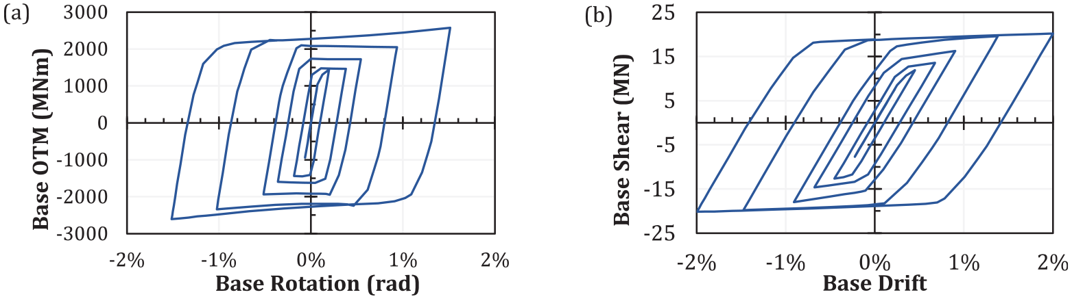
Base responses: (a) moment versus rotation and (b) shear versus drift ratio.
Nonlinear modeling of the benchmark structure
To further study the seismic response of the system compared to the benchmark structure, Nonlinear Time-History Analyses (NLTHA) were conducted in ETABS Nonlinear (CSI, 2019). Prior to analyzing the global response of the structure, validation of the nonlinear modeling approach for the proposed system was completed at the component level against the previously discussed detailed FE models in ABAQUS. In general, ETABS achieved reasonable accuracy for the force-deformation relationships of individual components even though it utilizes multi-linear hysteretic loops, including abrupt stiffness changes at yield points and load-reversals without modeling any of the expected rounding effects that are typical for yielding elements. Comparisons of the force-deformation relationships of individual components between the ETABS model and detailed FE models in ABAQUS can be found in Kent (2021). A nonlinear model of the benchmark structure was then developed in ETABS. The gravity system was excluded from the model as it has been shown to have a negligible effect on seismic performance (MacKay-Lyons et al., 2018), but the P-delta effects of the gravity system were simulated using a pinned column at the center of the core, tied to the remaining nodes by a rigid diaphragm constraint at each story. Embedded beams were modeled along each shear wall to generate a moment connection between coupling beams and walls. Accidental torsion was not considered. Only structural elements expected to form plastic hinges—that is, shear walls and coupling beams—were assigned nonlinear properties. Distributed plasticity was modeled in the shear walls using layered shell elements, which have been applied in different modeling software with the ability to properly capture the nonlinear behavior of typical RC shear walls (Hallinan and Guan, 2007; Lu et al., 2013, 2015). Constitutive material models defining the stress-strain relations for concrete and reinforcing steel are adopted from the PEER (2011) report and presented in Figure 6a and b, respectively. Reinforcing steel was assigned the “kinematic” model, while the “pivot” model was used for concrete (CSI, 2019). The “pivot” model was similar to the “Takeda” hysteresis model (Takeda et al., 1970) but included additional parameters α1, α2, β1 and β2 to better control degradation based on loading and unloading being directed toward specific points referred to as “pivot points” (CSI, 2019). Out-of-plane flexure and shear were modeled as elastic with reduced section properties of 0.25EcIg and 0.2Ec to account for cracking (MacKay-Lyons, 2013). The flexure-shear interaction of reinforcing steel was not accounted for. The modeling approach for the nonlinear behavior of shear walls was validated against experimental results by Thomsen and Wallace (2004). Coupling beam behavior was simulated through an elastic beam element with a zero-length nonlinear shear hinge at the center span. The backbone curve presented in Figure 6c captured the shear force-plastic rotation relationship of each hinge using the “Takeda” hysteresis model (Takeda et al., 1970). The coupling beam shear strength, V/Vn,code, plotted in Figure 6c was the ratio between the expected shear strength used in the model, V, and the American Concrete Institute (ACI)-calculated shear strength, Vn,code [ACI 318-19, 2019], based on recommendations by Naish et al. (2013). A 0.15EcIg property modifier was assumed for the elastic portion of the beam to capture slip deformations (MacKay-Lyons, 2013; Naish et al., 2013). Rayleigh mass and stiffness proportional damping factors were used with an assumed damping ratio of 2.5% assigned to the model at periods of 5 and 1 s (for reference, the first and second mode periods of the structure in the EW direction are 4.2 and 0.83 s, respectively), adopted based on previous studies to maintain consistency (MacKay-Lyons et al., 2018; Tong and Christopoulos, 2020; Zhong and Christopoulos, 2022).
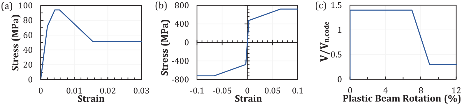
(a) Concrete constitutive model (Mander et al., 1988), (b) reinforcing steel constitutive model (MacKay-Lyons, 2013), and (c) coupling beam backbone curve (Naish et al., 2013).
The benchmark structure constructed in ETABS Nonlinear (CSI, 2019) was first validated against NLTHA results of the same structure used in previous studies using ABAQUS (Simulia, 2013; Zhong and Christopoulos, 2022), OpenSees (McKenna et al., 2010; Tong and Christopoulos, 2020) and Perform-3D (CSI, 2011; PEER 2011). The same Ground Motion (GM) suite used in these previous studies was used for a direct comparison of results. Table 1 summarizes the suite of seven GMs with their corresponding Record Sequence Number (RSN) (Ancheta et al., 2013) and scale factors for amplitude scaling to the MCE level for the benchmark building (PEER, 2011). Considering the symmetry of the building plan and the lack of detailed site information, each of the two-component of each GM was input along the principal horizontal directions and then repeated by rotating 90 degrees. The vertical components of GM were excluded from the analyses to maintain consistency with previous studies (PEER, 2011; Tong and Christopoulos, 2020; Zhong and Christopoulos, 2022). Table 2 compares periods and the mean peak base shears, base OTMs, inter-story drifts (IDRs) and floor accelerations (PFAs) among these studies, based on analysis results under the suite of GMs listed in Table 1. A reasonable correlation was achieved for key response parameters among the various analyses, validating the overall accuracy of the ETABS model. The largest discrepancy between the ETABS analysis and other software packages was in floor accelerations, which is likely attributed to the multi-linear (rather than rounded) hysteretic response of key yielding structural components in this modeling platform.
Ground motion used in model validation and parametric study
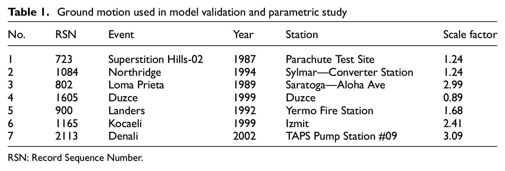
RSN: Record Sequence Number.
Comparison of mean peak response values.
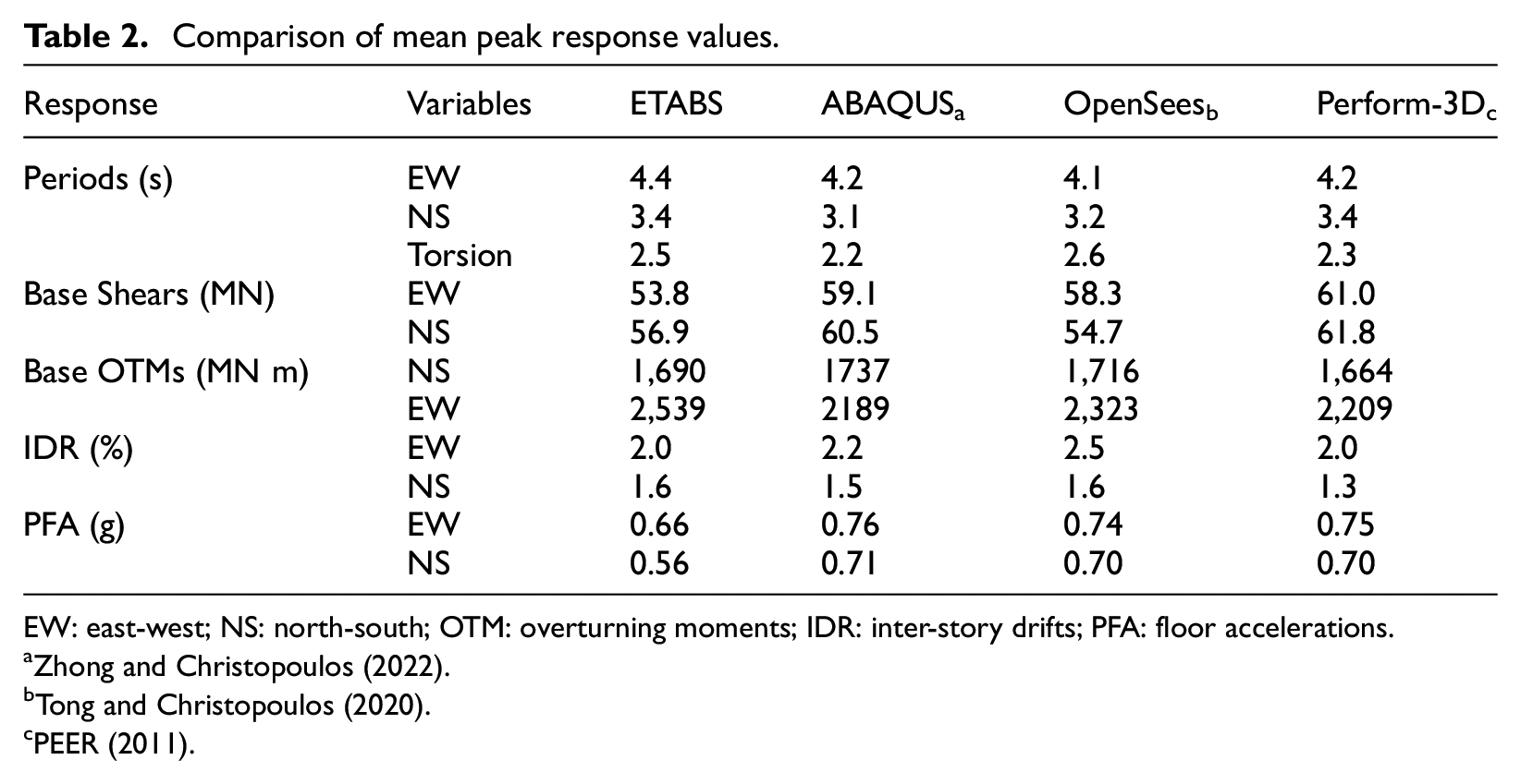
EW: east-west; NS: north-south; OTM: overturning moments; IDR: inter-story drifts; PFA: floor accelerations.
Nonlinear modeling of the benchmark structure with the proposed base mechanism
Following the validation of the benchmark structure model, the base mechanism proposed in this article was implemented and modeled at the base of the validated 3D ETABS benchmark building model. Basement slabs and walls were excluded from the model. A rigid slab between the core and the base-mechanism represented the PT system and transferred gravity forces in the elastic range. This assumption was found to have a negligible impact on the global performance of the structure. All BRBs were modeled using an elastic beam element with a nonlinear axial hinge at the center span. A bilinear stress-strain relationship was assigned to the hinges, as shown in Figure 7a, with the parameters of the BRB hardening model outlined in Figure 7b. These modeling parameters for the steel core of the BRB are based on the parameters adopted from Atlayan and Charney (2014). The behavior of the replaceable flexural yielding steel plates was idealized using axially rigid links with zero flexural capacity. All vertical BRBs were modeled with pin connections at their base to approximate the behavior of gusset plate or swivel connections at the two ends of the BRBs. These simplifications in the ETABS model assume perfect uncoupling of the flexure and shear mechanisms, although, as was established in the previous section, there would be minor interaction between them (Kent, 2021).
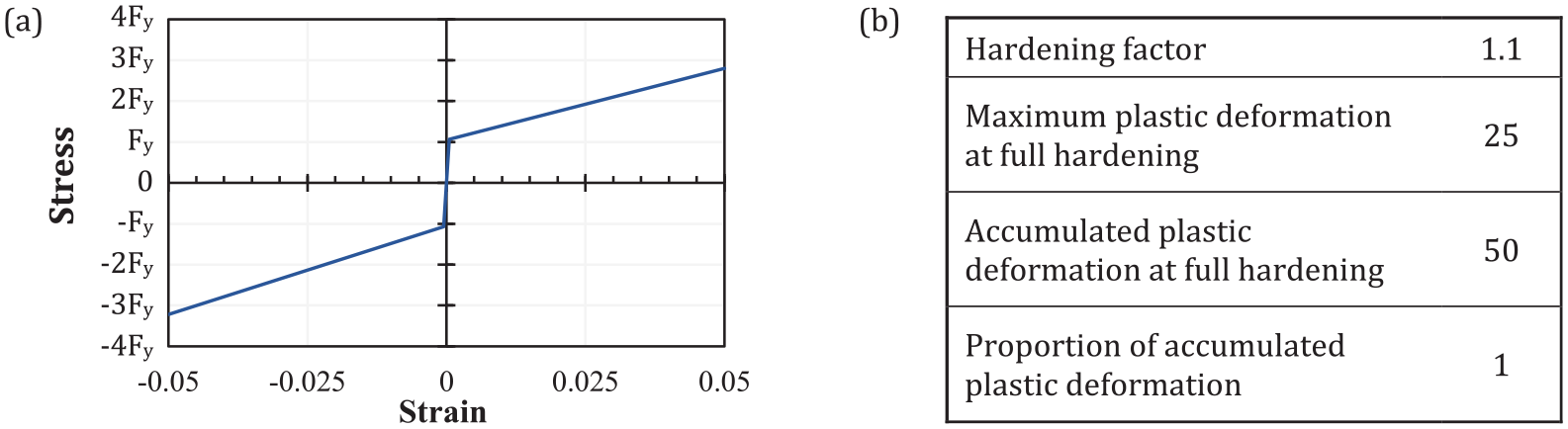
BRB nonlinear modelling: (a) backbone curve and (b) hardening parameters.
Parametric study on the benchmark building with the proposed base mechanism
In designing the shear system, a parametric study, using the 3D ETABS model and the same GM suite as summarized in Table 1, was first conducted to determine the optimal capacity for the braced BRB frames that control the base-shear demands of the structure. A weaker shear fuse reduces forces transferred to the superstructure at the expense of higher base drifts. Inversely, strengthening the shear fuse improves the base drift but is less effective in mitigating higher-mode effects in the superstructure. The optimal system requires a balance between limiting damage to the base level and the superstructure above. Using the definition proposed by Tong and Christopoulos (2020), the base-shear resistance is denoted as κVVu where κV is a factor representing the shear strength reduction as a fraction of the demands for a conventional fixed-base design, Vu, under MCE events. For the benchmark structure, Vu values were 53.8 MN in the east-west direction and 56.9 MN in the north-south direction. The values of κV ranging from 0.6 to 1.0 were considered for the parametric study. Note that a value of κV = 1.0 represents the proposed system designed for a similar level of base-shear and moment demands as expected under MCE level earthquakes for the benchmark structure. For each target base-shear resistance level, braces were sized using the following equation:
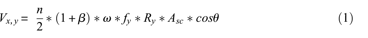
where n represents the number of braces, β accounts for the increased strength of BRBs in compression, ω is the strain hardening factor, fy is the nominal yield strength of the steel, Ry is the expected overstrength factor, Asc is the area of the brace steel core, and θ is the brace inclination angle. Table 3 summarizes the target base-shear resistance levels used in the parametric study. These target base-shear resistance levels could be achieved by either adjusting the yield strength of the steel, fy, or the total area of the brace steel core, Asc. The latter would result in slightly elongated initial periods (less than 5% increase) for structures with lower base-shear resistance levels due to the reduced initial stiffness of the proposed system. For the parametric study presented in this article, the same total areas of the brace steel core, Asc, in each principal direction were used to ensure that the system had the same initial stiffness under different base-shear resistance levels, thus enabling a direct comparison for different base-shear resistance levels.
Target base-shear resistance for the parametric study
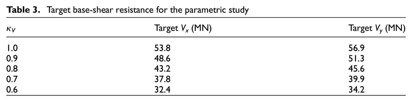
Results for mean peak story shears, IDRs, PFAs, wall rebar tensile strains, and coupling beam rotations along the structure height are plotted in Figure 8. Table 4 summarizes the periods and mean peak responses for the base shear, IDRs, and PFAs for each κV case. In comparison with the benchmark building, the results of the proposed system with κV = 1.0 showed slightly elongated initial building periods because of the reduced initial stiffness at the base in comparison with the initial stiffness of a fully fixed structure (i.e. the benchmark structure). There were also reductions in both base-shear demands (2.4% in the EW direction and 2.3% in the NS direction) and IDRs (1% in the EW direction and less than 1% in the NS direction) when the proposed system with κV = 1.0 was added to the benchmark building, likely due to the elongated initial building periods and a better controlled yielding mechanism of the proposed system than relying on the yielding of the base plastic hinge zone in the benchmark building. As the values of κV ranged from 1.0 to 0.6, periods of the structure remained unchanged, while the base-shear and IDR demands were continuously reduced at the expense of increased base drift (i.e. displacement demands in the proposed system). Among these results, a κV of 0.6 achieved the greatest reduction in comparison with the benchmark, and a κV of 1.0 the least. For all cases, tensile strains in the longitudinal reinforcements of the wall were reduced to below the yield level of 0.2%. Beam rotations are shown in Figure 8e for the coupling beams “CB12” as marked in the coupling beam layout in Figure 3c. For the case with κV = 1.0, 18 beams surpassed 0.02 radians of rotation, indicating a need for repair as suggested by Naish et al. (2013). This value was reduced to 8 for κV = 0.8 and zero for shear strengths below this. An inverse relationship between peak base drift and peak IDRs in the superstructure was observed; the case of κV = 0.6 produced the lowest IDRs in the superstructure, but the highest deformation at the base. Based on the results of the parametric study, a shear strength reduction factor of 0.7 exhibited the best balance between mitigating base and superstructure damage (Kent, 2021). At this capacity, all damage to the superstructure was eliminated, and base drift was significantly lower than for κV = 0.6%—3.8% for κV = 0.7 compared to 5.2% for κV = 0.6. While the base drift ratio of 3.8% for κV = 0.7 was below the experimentally determined maximum drift level for BRBs of up to ±5.0% (Lanning et al., 2016; Yamaguchi et al., 2004), a base drift ratio of 5.2% for κV = 0.6 confirmed that the peak BRB drift ratio was one of the design constraints for the proposed system. A shear strength reduction factor of 0.7 corresponded to mean peak base-shear values of 43.2 MN and 45.7 MN in the east-west and north-south directions, respectively. Similar results were observed by Tong and Christopoulos (2020), who suggested that a mean peak base-shear of approximately 40 MN resulted in the optimal performance of the benchmark structure.
Results of the shear strength parametric study: (a) story shears, (b) inter-story drift, (c) peak floor accelerations, (d) rebar tensile strain from S-W wall, and (e) beam rotation from coupling beam CB12.
Comparison of mean peak response values for the benchmark building with the base mechanism
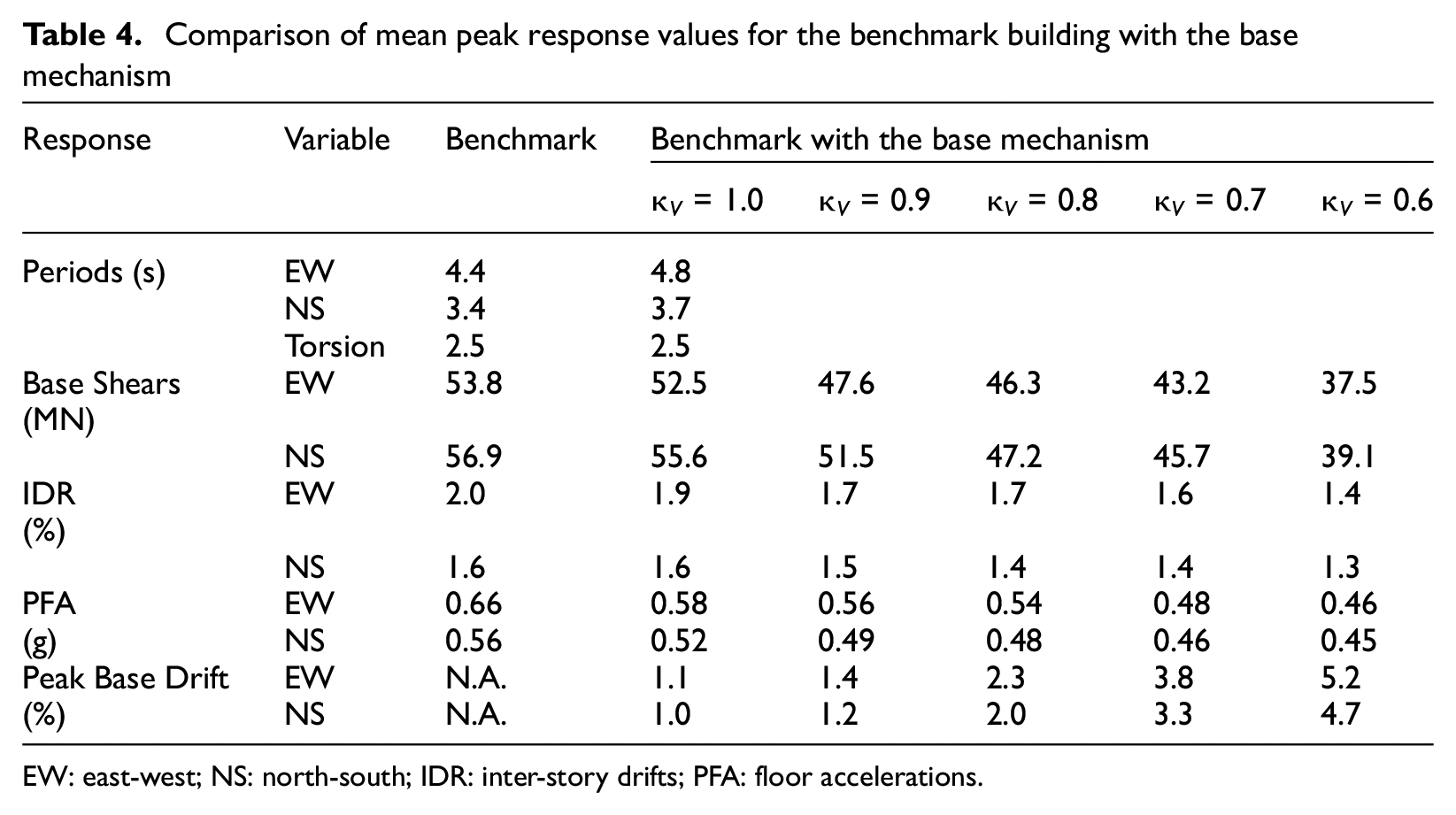
EW: east-west; NS: north-south; IDR: inter-story drifts; PFA: floor accelerations.
Seismic performance evaluation of proposed system
In this section, the seismic performance of the benchmark structure equipped with the proposed base-mechanism designed with a κV value of 0.7 (chosen as an optimum design for the benchmark building based on the parametric study) was further evaluated in comparison with the benchmark structure for three hazard levels: SLE, Design Earthquake (DE), and MCE. The NLTHAs were conducted following the procedures of Chapter 16 of ASCE/SEI 7-16 (ASCE, 2017), and as recommended by the two performance-based seismic design guidelines for tall buildings (Los Angeles Tall Buildings Structural Design Council (LATBSDC), 2020; PEER, 2017). Two suites of 11 site-specific GMs were selected from the PEER NGA-West 2 GM Database (Ancheta et al., 2013). The average of the maximum-direction spectra from each suite was amplitude matched to the SLE and DE spectrum, as well as two site-specific target MCE response spectra (as illustrated in Figure 9) for the benchmark building located at a near-fault site in Los Angeles over the period range of 0.2Ta to 2Ta, where Ta is the largest first-mode period in the principal horizontal directions of response. Each suite consisted of seven far-field GMs and four pulse-like GMs, recognizing that the pulse fraction for the Los Angeles site is 0.38. A summary of the selected GMs and the corresponding scaling factors is presented in Table 5.
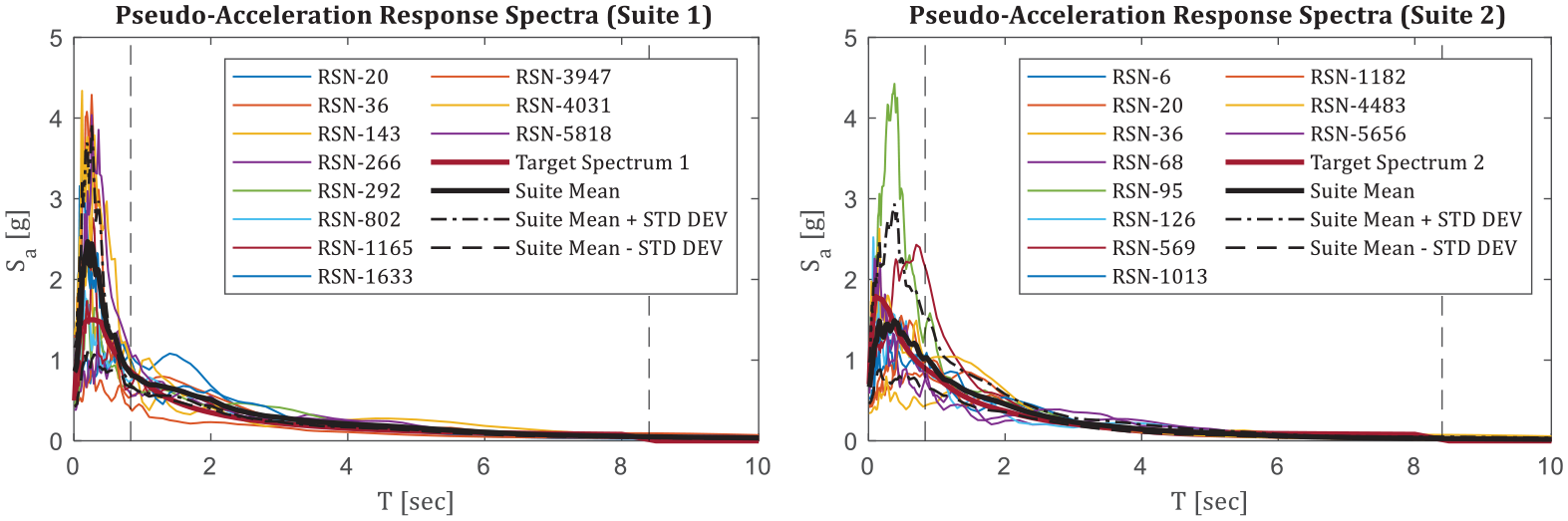
Scaled acceleration spectra of the ground motion suites at the site-specific target MCE-level.
Ground motion used in seismic performance evaluation
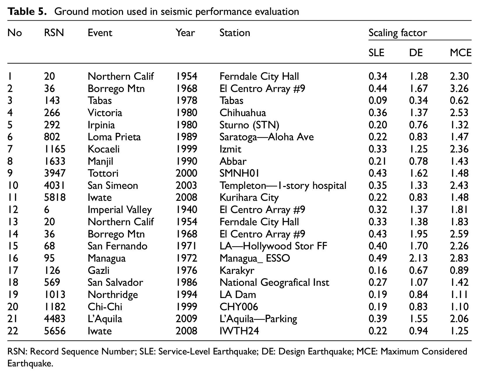
RSN: Record Sequence Number; SLE: Service-Level Earthquake; DE: Design Earthquake; MCE: Maximum Considered Earthquake.
Mean envelopes of story shears, PFAs, and IDRs in the east-west direction along the height of the benchmark structure with and without the proposed base-mechanism are presented in Figure 10. Similar results were observed in the north-south direction. Figure 11 shows the mean longitudinal reinforcement tensile strains at the south-west and north-west corners of the core wall along its height. Figure 12 plots mean peak coupling beam rotations at three of the six coupling beam locations (as indicated in Figure 11). Since longitudinal reinforcement of the core wall and coupling beams remained in the elastic range for both the benchmark structure and the structure with the proposed system under the SLE-level earthquakes, these results are not included in Figures 11 and 12.
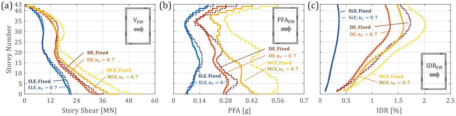
Performance comparison among SLE, DE, and MCE level earthquakes: (a) story shear envelope, (b) peak floor acceleration envelope, and (c) inter-story drift ratio envelope.
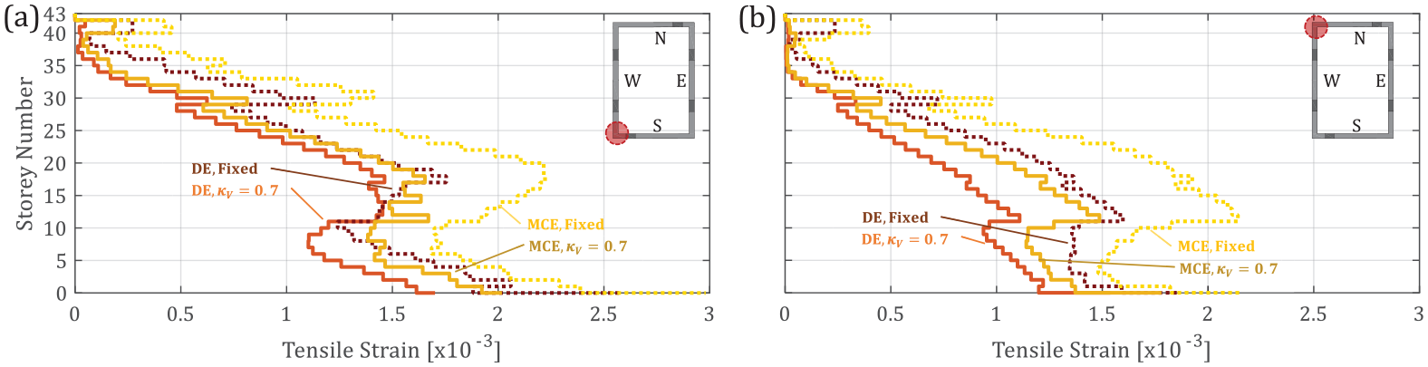
Comparison of RC wall tensile strain envelopes between DE and MCE level earthquakes: (a) SW corner and (b) NW corner.
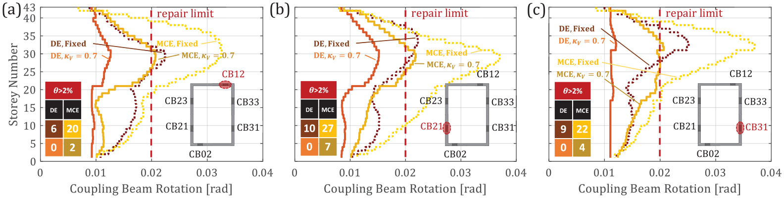
Comparison of coupling beam rotation envelopes between DE and MCE level earthquakes: (a) CB12, (b) CB21, and (c) CB31.
At the serviceability level, only minor changes were observed in the structural response. The base-shear demands and the IDRs along the height were nearly identical to the benchmark structure. PFAs were slightly increased near the base but decreased for the rest of the structure. At the DE level, slightly larger differences were observed in the structural response. Story shears were decreased along the lower half of the structure, with mean peak base-shear being reduced by 10% and base OTM by 7%. Inter-story drifts and floor accelerations were also decreased along the height of the building, as seen in Figure 10b and c. Significant improvements in longitudinal reinforcement tensile strains were also observed along the building height, with a mean peak strain at the base of 0.14% compared to 0.26% in the benchmark structure, and no longitudinal reinforcement reached yielding. In the benchmark structure, the 0.02 radians rotation limit for coupling beams was surpassed at 6, 10, and 9 floors for the CB12, CB21, and CB31 coupling beams, indicating that repairs at these floors would be required. With the proposed system, the maximum coupling beam rotation was only 0.014 radians, eliminating all need for repairs. At the MCE level, even larger reductions were observed for story shears, IDRs, and PFAs. Tensile strains of longitudinal reinforcements were reduced to approximately 75% of the benchmark values along most of the building height and did not reach yielding. Coupling beams at 2, 7 and 4 floors exceeded the repair limit of 0.02 radians rotation for the CB12, CB21, and CB31 coupling beams—a significant decrease from 20, 27, and 22 floors for the same CB12, CB21, and CB31 coupling beams in the benchmark structure. The overall number of coupling beams surpassing the repair limit was decreased from 99 to 18, representing an 80% decrease in the number of coupling beams requiring post-earthquake repair. As for the reparability of non-structural components within the structure, when an IDR limit of 1% was considered as an example (Algan, 1982), the number of stories exceeding the 1% IDR limit was 23 at the DE level and 27 at the MCE level for the building with the proposed system, while for the benchmark building, the numbers increased to 29 and 33, respectively.
Overall, the implementation of the base-mechanism enhanced the seismic performance of the building, with the most significant improvements occurring at the DE and MCE levels. Inter-story drifts, floor accelerations, rebar strains, and beam rotations were reduced along the structure’s height, indicating less structural and non-structural damage to the building. In addition, as shown in Figure 10a, the relative increase in the story-shear envelope from DE-level earthquakes to MCE-level earthquakes was more significant for the benchmark structure than for the structure with the proposed system, likely due to the increased contribution from higher modes of vibration with the increase of GM amplitudes. With the proposed system, this relative increase in the story shear envelope was reduced by more than 50% along the height. The shapes of the PFA and IDR envelopes also exhibited smaller relative increases from DE-level results to MCE-level results, as illustrated in Figure 10b and c. Although the shapes of the demand envelopes still indicate higher-mode contributions to the response of the structure with the proposed system, the differences in seismic demands between the structure with and without the proposed system highlight the reduced higher-mode effects achieved by limiting the base-shear transfer through the proposed system. Moreover, under MCE-level earthquakes, the highest values of the peak base drift were 3.1% in the east-west direction and 3.8% in the north-south direction, and the highest values of the peak roof drift were 0.81% in the east-west direction and 0.68% in the NS direction (which were similar to 0.82% and 0.73% for the benchmark structure). The peak displacement demands of the BRBs and rotation demands of the flexural-yielding plates were also checked under MCE-level earthquakes, which were both below the maximum allowable values determined in the detailed design of these components, confirming no excessive damage or strength degradation.
Figure 13 presents the residual IDRs for the MCE level, which showed approximately 50% reduction from the benchmark structure to the structure with the proposed base mechanism. At the base of the structure, there was a mean residual drift of 0.4% from the buckling-restrained braced frames in the east-west direction and 0.25% for the north-south direction. In addition, a mean residual compression of approximately 20 mm, or 0.4% of the base height was observed. The maximum residual drift in the superstructure was 0.25% for the east-west direction and 0.19% for the north-south direction. A significant portion of the residual drift response was due to residual base rotation resulting from the inelastic response of the vertical BRBs. In each direction, approximately 0.1% of residual drift along the structure height was due to rotation at the base. The remainder of the residual IDRs can be attributed to the response of the coupling beams. As seen in Figure 12, inelastic rotational demands on the coupling beams were greater in the top half of the structure, corresponding to greater residual drifts. Repairs and re-centering of the base mechanism may be done by replacing these braces sequentially with temporary support where each brace is removed without destabilizing the structure. This is expected to reduce both repair costs and downtime for the building.
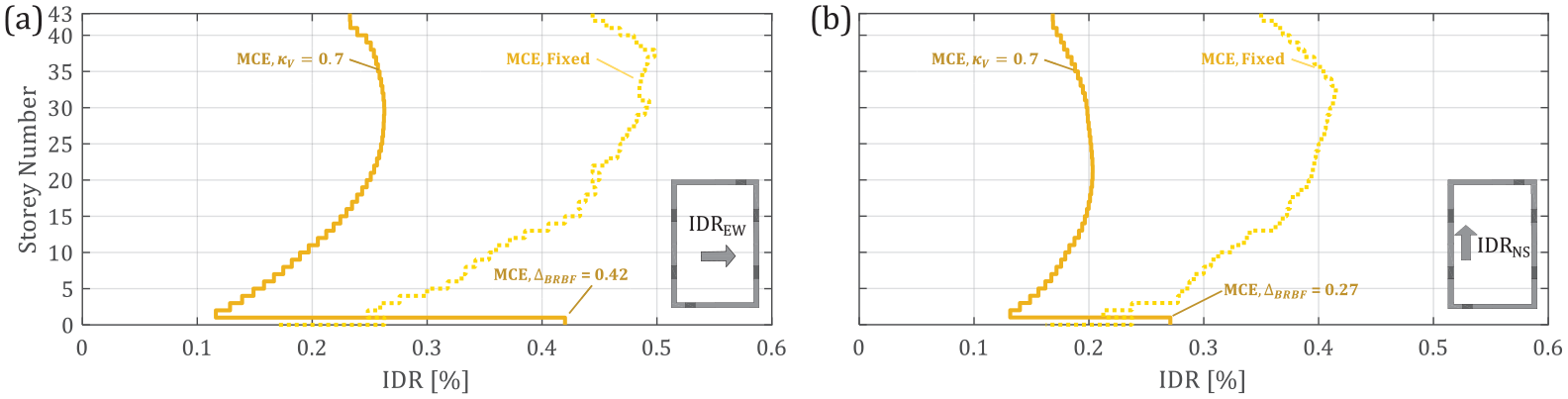
Comparison of residual drifts under MCE level earthquake: (a) E-W direction and (b) N-S direction.
Conclusion
This article proposed a new configuration of steel BRBs incorporated at the base of high-rise buildings to improve the seismic performance of RC coupled high-rise structures and achieve an uncoupled flexure and shear response. Vertical braces below the core system create a flexural fuse while braced frames outside of the core limit the shear response. By limiting both bending moments and shear forces at the base of the structure and elongating the elastic and inelastic periods, the first mode and higher-mode responses of the building are reduced. The core system and outer slab are connected using replaceable flexural yielding steel plates that form flexural plastic hinges, thus limiting the transfer of vertical forces and uncoupling the systems while still transferring diaphragm forces from the core to the outer BRB frames.
The system was developed and designed for a 42-story benchmark structure. The flexural system was designed such that the yield moment corresponded to the base moment associated with the SLE hazard level. A parametric study was conducted to determine the optimal shear capacity of the base-mechanism that would mitigate both base and superstructure damage. To best balance these two parameters, a shear strength reduction factor, κV, was established and values of 0.6 to 1.0 (in increments of 0.1) were investigated. A κV of 0.7 was found to be optimal for this structure, significantly reducing the number of coupling beam repairs while adequately controlling the peak base drifts. For the design of new structures equipped with the proposed system, the optimized value of κV is expected to vary for different structures and should be selected on a project-by-project basis. The design of the superstructure should follow a capacity-design approach such that the superstructure remains nearly linear elastic under MCE level earthquakes.
NLTHA was conducted at three hazard levels (SLE, DE, and MCE) to compare the performance of the base mechanism to the benchmark structure. The implementation of the proposed base-mechanism system showed improved seismic performance of the structure, especially with the increase in hazard levels. Longitudinal reinforcement yielding in the walls was eliminated and excessive coupling beam rotations were reduced. Inter-story drifts and peak floor accelerations were also reduced along the structure’s height, indicating reductions in the overall structural and non-structural damage.
While the proposed system was studied based on a 42-story benchmark high-rise structure in this article, it can be extended with future research to a wider range of structural types and heights by adjusting the configuration and capacity of the flexure and shear mechanisms. To further explore this high-performance system, it is recommended that a larger suite of GMs be considered. Physical testing is recommended for the BRB connections, as well as for the replaceable flexural-yielding steel plates to ensure that strength and ductility demands are achieved without any low cycle fatigue-induced fractures. All component testing should include loading in 3D to appropriately account for the multi-directionality of the applied loading. Further investigations are also required for the vertical BRBs to understand the effects of the long-term pre-compression that is being applied by the gravity loads. Consideration for repairs of both structural and non-structural components as well as re-centering of the system after a major event, wind response, and comprehensive cost analysis should also be carried out to better understand the full performance and potential benefits of this mechanism.
Footnotes
Declaration of conflicting interests
The author(s) declared no potential conflicts of interest with respect to the research, authorship, and/or publication of this article.
Funding
The author(s) received no financial support for the research, authorship, and/or publication of this article.