
Abstract
This article reports mixability experiments and their RGB color model analysis for a simple structured micromixer based on the pneumatic-driven membrane in multiple microreagent mixing applications. First, a novel and simple structure consisting of a mixing chamber and a pneumatic chamber is designed and fabricated of polydimethylsiloxane (PDMS) material, which facilitates integration with microfluidic chips. Then, experiment results and their RGB color model about mixing efficiency are investigated. Compared with conventional methods, the RGB color model for mixing results is easy and intuitive. In addition, the designed micromixer operation relies on less external laboratory infrastructure because of its simple structure.
Introduction
A micromixer is a crucial component in many microfluidic applications, especially in biochemical analysis and biological fields requiring two or more liquid streams to mix.1,2 At microscales, laminar flow conditions prevent mixing except by diffusion. However, diffusion does not happen fast enough to provide an adequate means of mixing in some microfluidic-based assays, particularly those that require relatively large particles, for example, cells.3,4 To overcome this problem, numerous novel passive and active micromixers are currently being designed and developed. For increasing interfacial contact areas of different liquid samples and consequently achieving better mixing, passive mixers use channel geometry to fold fluid streams.5,6 The drawbacks of these passive micromixers are complicated fabrication and increasing the failure rate during device manufacturing because of longer microchannels and various complex design structures.
The active mixing can be achieved through a variety of approaches. These include magnetic, 7 electrokinetic, 8 hydrodynamic, 9 and PZT-based 10 actuation, among others. One popular and promising configuration for an active micromixer is the pneumatic micromixer, which is actuated by external positive or negative air pressure, and the pneumatic micromixer is commonly employed in microfluidic networks. Additionally, one exception is pneumatic actuation microdevices, which usually use actuators located outside the fluidic chips, while other actuators must be embedded in the microfluidic chips. The bulky volume of actuators will definitely affect the degree of microfluidic large-scale integration. The control and pressure generation system are usually hosted off the chip for the pneumatic microchip. Therefore, it becomes possible to develop a microfluidic chip with thousands of integrated micromechanical micromixers, microvalves, and other control components. Quake’s research group reported that a pneumatic rotary micromixer is formed of three pneumatic actuators, which is also utilized as a pneumatic micropump. The micromixer has the same principle of the pneumatic pump but a different outside form.11,12 Due to the shorter diffusion distance for mixing, the mixing time can be reduced to a matter of seconds compared with several hours for passive diffusion. A novel pneumatic micromixer was studied by Hsiung et al., who used two pairs of side moving walls activated pneumatically for mixing of the samples in both dynamic symmetric and dynamic asymmetric modes. 13 Such a micromixer, including two or four pneumatically driven polydimethylsiloxane (PDMS) membranes, was developed by Yang and coworkers.14,15 The swirling flow field, the concentration distribution, and the mixing mechanism are also given in the computational fluid dynamic simulation software. However, previously developed pneumatic micromixers have a somewhat complex pneumatic structure and are either too troublesome to encapsulate or hard to handle. Besides, these pneumatically actuated micromixers are hard to operate and require much peripheral equipment for air supply and control.
Measuring methodology to investigate the effectiveness of micromixers in microfluidic chips is another challenge because of narrow, small, and enclosed spaces in microfluidic chips. The standard for judging the completion of mixing of two or three different color reagents is a uniform color viewed with the naked eye. 16 The drawback of this method is an inaccurate judgment because of many objective factors, such as light, observation location, and optical parallax. Moreover, quantitative mixing efficiency is obtained by a fluorescence microscope to acquire the images, and digital image processing techniques are used to evaluate the mixing efficiency, 17 in a small, confined space in microchannels and sealed microchannel networks in microfluidic chips. The disadvantage of this quantitative method is costly and complicated postprocessing. What is more, the mixing efficiency is estimated by measuring the color ink or microbead concentration. Therefore, this quantized evaluation method for mixing efficiency is inconvenient and indirect.
In this study, a simple structured pneumatic micromixer capable of generating a vortex-type flow and reducing external pneumatic control valves is demonstrated. Moreover, a novel mixing experiment analytical methodology, a RGB color model, is proposed and implemented for quantitative analysis of the mixing results. Experimental data show that this type of mixing and mixing efficiency quantitative methodology can be used in bioreactions, incubation, and other biological applications.
Mixing Efficiency Based on RGB Color Model
We used a digital charge-coupled device (CCD) camera for capturing red, green, blue (RGB; three primary colors) data of a mixing image to achieve colorimetric measurements. The conversion of the RGB model to a gray model can be realized through the method of color mode expression. Ri, Gi, and Bi represent the three primary color R, G, and B values of each pixel, respectively, and the gray data (Ci) of each pixel are obtained by calculating the mean value of its RGB data. According to the human eye’s sensitivity to the primary color, weights of the linear weighted average are defined to compensate nonuniformity of the sensitivity. The weight values of the general R, G, and B components are 0.299, 0.587, and 0.114, respectively. The conversion model can be expressed by eq 1: 18

The mixing efficiency of the grayscale difference evaluation method is based on the color distribution. Using the image color uniformity of the measured area to evaluate the mixing efficiency degree, the whole image color uniformity is expressed by calculating the deviation for the grayscale difference of each pixel and the gray value of other pixels. For example, the pixel resolution of a CCD image is m × n; the grayscale deviation (Eij) between the pixel (i, j) and the pixel (p, q) is defined in eq 2: 19
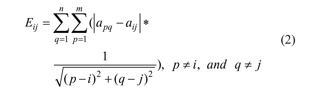
where aij is the grayscale of the pixel (i, j), apq is the grayscale of the pixel (p, q), and Eij is the weighted sum of the pixel (i, j) to other pixels. The total grayscale difference (Etotal) of the whole image is defined as eq 3: 20
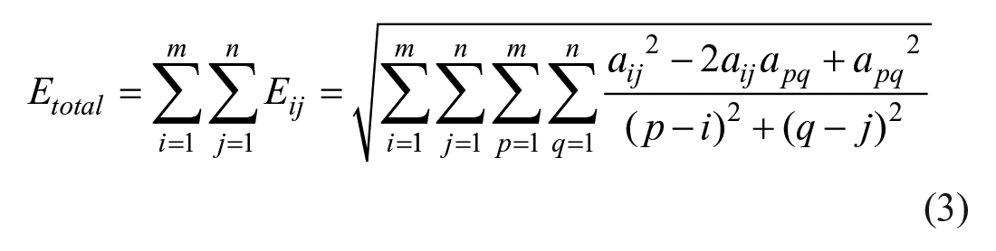
The mixing efficiency can be quantified using the following mixing efficiency index (Imix), which is expressed by eq 4:
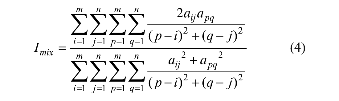
Imix is used to evaluate the mixing efficiency degree of a digital image, and the method of calculating the digital image mixing efficiency is direct and clear. However, the calculated amount of the method is huge because the deviation between each pixel and the other pixels needs to be calculated. Therefore, the mixing efficiency of the mixed area is evaluated by using the simplified grayscale deviation. The definition of mixing efficiency (Imix) is calculated by eq 5 and eq 6: 21


where N is the number of pixels in the measurement area, Ci is grayscale of the pixel point (i), and
Experimental
Selected Materials and Apparatus
PDMS is employed as the primary structural material for the micromixer. It has many attributes that are ideal for microfabrication, including biocompatibility, flexibility, transparency, and ease of fabrication relative to other common microfabrication materials. 22 Furthermore, PDMS has a much lower Young’s modulus than other hard materials, such as silicon and silicon nitride, 23 enabling it to be used as the deformable membrane of microfluidic devices, which is important for the pneumatic micromixer. Due to these useful traits, many microfluidic chips have been fabricated almost exclusively with the use of PDMS.
The negative dry-film photoresist FF-9050S, with a uniform thickness of 50 μm, used in this paper was purchased from the Changchun Group Company of China. A thick positive photoresist (AZ 50 XT, Hunan Jiazhaorui Technology Co., Ltd., China) is used to fabricate microchannel networks mold with a rounded cross section. A suit of PDMS prepolymer solution (Sylgard 184, base and curing) was purchased from Dow Corning Corporation of the United States. A photofilm is used for fabricating a photomask by an inkjet printer (Stylus Photo R2000, Seiko Epson Corporation, Suwa, Janan).
The apparatus for fabricating the pneumatic layer with a rectangle cross section consists of a high-resolution inkjet printer, a pressing film machine (LR-230, Yatai Office Facilities Company, Wenzhou, China), and an ultraviolet lamp (UVC-25W, Shenzhen New Modern Technology Company, Shenzhen, China). The equipment for producing the liquid sample layer with a rounded cross section consist of a spin coater (KW-4A, Chinese Academy of Sciences Institute of Microelectronics, Peking, China), an exposure device (URE-2000/35, Institute of Optics and Electronics, Chengdu, China), and an oven (JR-2020, Xincheng Co., Ltd, Shenzhen, China) for heating. A commercially available plasma cleaner (PDC-MG) machine system was purchased from Mingheng Co., Ltd. (Chengdu, China) and was used to enhance the cured PDMS surface properties. The mixing process and results are observed and recorded by a stereomicroscope (MA2003A, Mashide Company, Shenzhen, China) with a CCD camera.
Design and Fabrication
Figure 1 shows the structure and operating principle of two different color samples to be mixed. The samples come in through the reservoir and pass through a flow-focusing microchannel, and then the two liquids flow into the mixing chamber. The upper mixing chamber and the bottom actuated chamber constitute the pneumatic micromixer. The two layers are separated by an elastic thin PDMS membrane, which is the most important and only active part. Its deformation exerts a tremendous influence on the mixing characteristics of the pneumatic micromixer. A three-way microvalve is utilized to control the actuated chamber pressure. When mixing behavior is required, a voltage is supplied on the three-way microvalve, which opens it so that air can be supplied to the actuated chamber. The pressure in the actuated chamber increases and the thin PDMS membrane can be deflected upward; the deflectable thin membrane recovers after the air pressure is turned off, because of its elasticity and the weight of liquids in the mixing chamber. The thin membrane can be moved up and down continuously by controlling the three-way microvalve. This can generate a vortex-type flow inside the mixing chamber. The mixing process is observed and captured by a stereomicroscope with a CCD camera, which is used to acquire the digital images of the actuated chamber. The CCD camera is connected to an image processing system, which is used to quantity the mixing efficiency. Then, well-mixed liquid is pumped by the peristaltic micropump, consisting of three parallel arranged pneumatic microvalves.
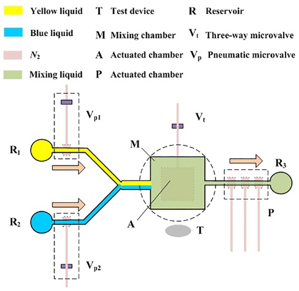
Structure of the pneumatic micromixer.
The pneumatic layer with a rectangle cross section is fabricated based on a dry-film negative photoresist mold. The liquid sample layer with a rounded cross section is fabricated by reflowing the positive photoresist mold. The square mixing chamber with arc corners and microchannels with an arc of the edge can be realized by the reflow fabrication process. Detailed information about the fabrication process can be found in our previous studies.24,25 The measured sizes of the mixing chamber and actuated chamber are 1.0 × 1.0 × 0.1 mm and 0.8 × 0.8 × 0.1 mm, respectively, as shown in Figure 2 . The center positions of the mixing chamber and actuated chamber overlap, forming a symmetrical structure. The air microchannel connected to the actuated chamber and the liquid microchannel connected to the mixing chamber are perpendicular in space. The thickness of the middle-layer thin membrane is 40 μm, which is spin-coated by the spin coater at 1500 rpm.
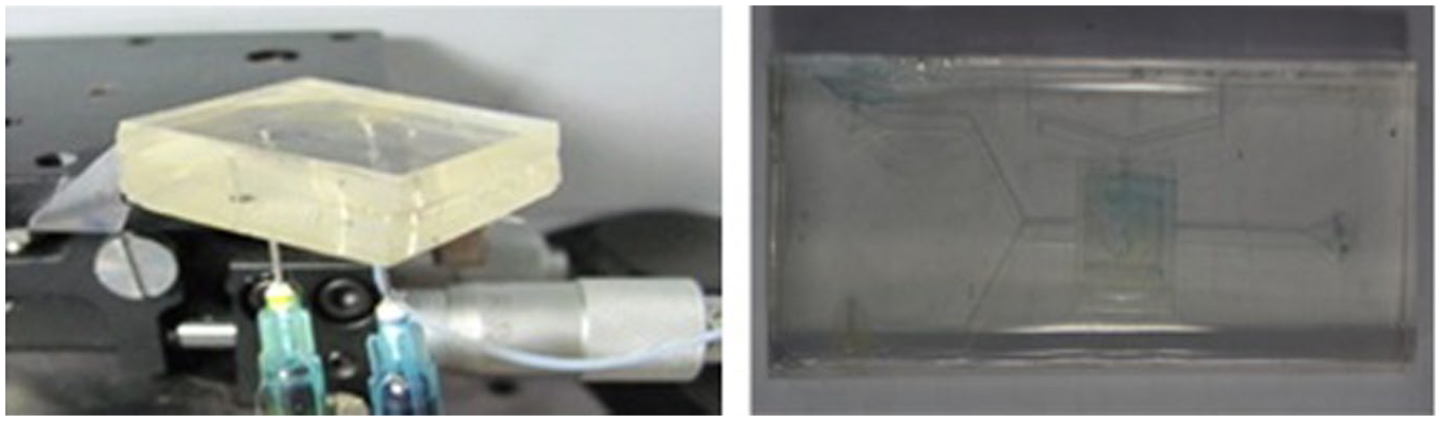
Pictures of the packaged PDMS pneumatic micromixer.
Fluidic Mixing
Due to the square mixing chamber with arc corners and the microchannels with an arc of the edge, a fast and residue-free liquid flow can be realized. Before experiments, the microdevice is washed with deionized (DI) water for 10 min to push out air bubbles in the mixing chamber. Blue and yellow, two bright and easily distinguished colors, are used in the mixing performance experiment. Blue and yellow reagents are for two different samples. Blue and yellow reagents are made using two watercolor pigments and DI water with a quality ratio of 1:1. Watercolor pigment particles are exquisite and have water solubility, and the color of the reagents is high, which makes them conducive to micro-observation and the collection of digital images. About 0.04 μL of DI water with yellow dye and about 0.02 μL of DI water with blue dye are pipetted into the mixing chamber by a suit of fluid driving setup, which is described in previous literature. 26 Note that, according to the color-matching principle, when there is more blue reagent than the yellow reagent, the mixture reagent color observed by the human eye is gray. Otherwise, it is green.
The mixing process and results are recorded by taking photos in the retry time interval using the stereomicroscope. The images may be reflective and have manufacturing defects because of limited test conditions. The color difference caused will create background errors for calculating the mixing efficiency. Therefore, the above defective pixels should be removed after reading the RGB values of the mixing chamber images to reduce the calculation error.
Results and Discussion
To investigate the performance of the micromixer and the practicability of the RGB color model, the mixing effect contrast of the micromixer and the free convection is investigated. Moreover, the effects of several operating parameters, including driving frequency and driving air pressure applied to the thin PDMS membrane, are first explored. The mixing results are recorded by taking photos in the retry time interval using the stereomicroscope.
Mixing Effect Contrast
Figure 3a shows a series of photographs for the free convection of the mixing chamber at different times. The change of the color intensity shows that an almost completely mixing process of samples has been achieved. According to the color of the microscope photos, we can see that the two samples with different colors have not yet fully mixed after 25 min under the conditions of the free convection mixing process. Figure 3b shows a series of photographs for the vibrating mixing process. The liquid samples can be rapidly mixed under the action of the proposed pneumatic micromixer. The applied pressure and driving frequency are 20 kPa and 1 Hz, respectively, for this case. These images prove that the two samples with different colors are almost completely mixed after four times shock.
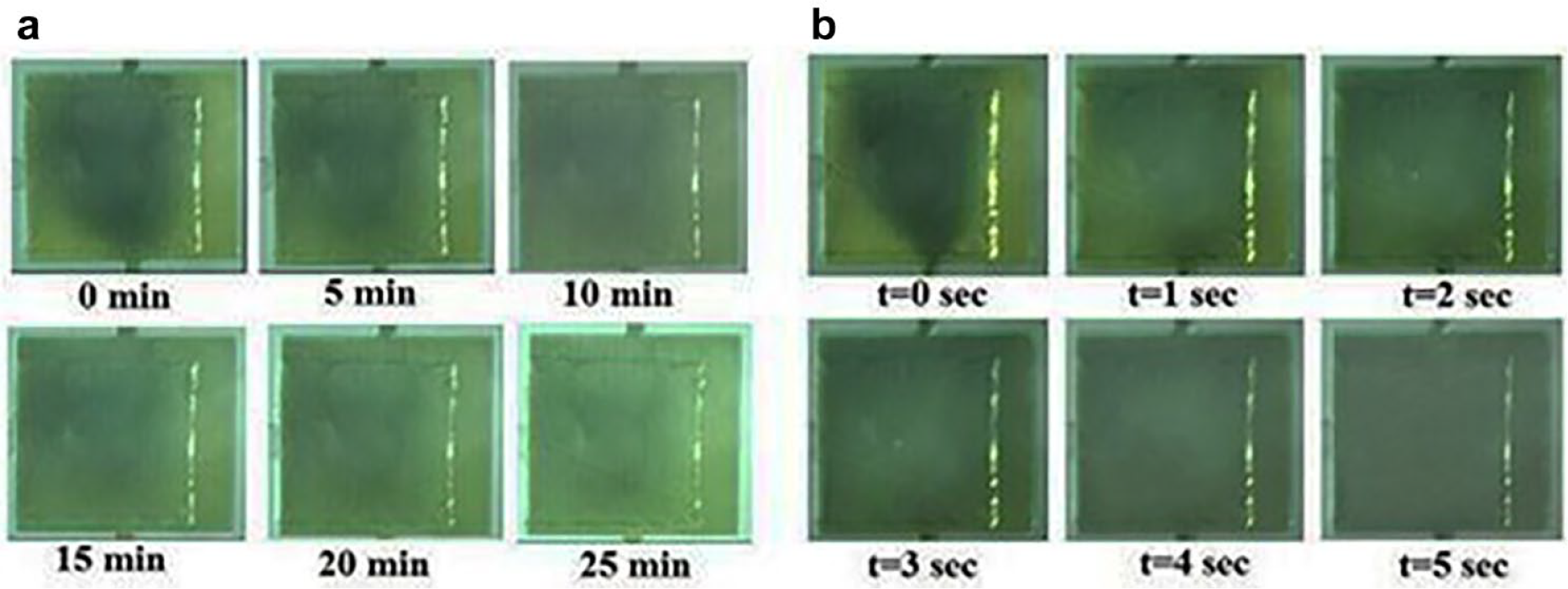
A series of microscope photos at different times. In the inset, two photographs show the concentration profile in the mixing chamber without mixing after 25 min and with mixing by the proposed mixer after 5 s. (
Figure 4 shows the quantitative mixing efficiency based on the RGB color model described earlier and corresponds to the photos shown in Figure 3 . The mixing efficiency under the unmixed condition is found to be only 68.75% after 25 min due to molecular diffusivity, and experimental results show that the mixing efficiency throughout the mixing chamber is as high as 94% after mixing for 5 s in 1 Hz at 20 kPa. After 5 s, the mixing efficiency barely changed. This is because after 5 s of vibration by the proposed micromixer, the microreagents in the mixing chamber are almost completely mixed. In addition, when the two different color reagents are almost completely mixed, the digital picture color of the mixing chamber is almost unchanged, and the mean value of their RGB data is almost unchanged; consequently, the quantity mixing efficiency is almost unchanged.
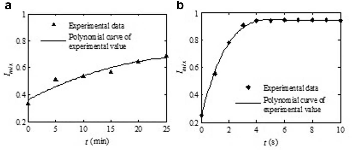
Mixing result comparison of reagents in the micromixing chamber caused by free convection and the microactuator. The mixing efficiency of the pneumatic mixer can be as high as 94% after 5 s. (
Driving Frequency
The effect of the driving frequencies on the mixing efficiency has been investigated in this study. The mixing chamber has a smaller space compared with a macro-size mixing device, and the lateral convection flow field is more complicated than that of the mixing chamber. In addition, the inlet channel of the pneumatic microdriver is relatively narrow and the flow resistance is relatively large, resulting in long charging and exhaust times. Therefore, the higher actuated frequency is not suitable for the pneumatic micromixer with a longer response time. Furthermore, the vibration frequency of the PDMS pneumatic mixer should not be too high for clearly observed and recorded.
The deformation of the elastic thin PDMS membrane is determined by the actuated pressure and its geometrical size; see our previous study 27 for the formula of deformation of the thin PDMS membrane. The response time of the pneumatic micromixer depends on the off-chip electromagnetic microvalve, air resistance (geometric size of the microchannel connecting the air supply and micromixer), and volume of the actuated chamber. The effect of the PDMS material relaxation time on the response time of the micromixer is negligible (<10 μs). In our previous study, the response time of the micromixer was less than 28 ms when the actuated pressure was 150 kPa. The results prove that when the actuated pressure decreases, the response time of the micromixer decreases with constant other influential factors. In this paper, the response time is far less than 28 ms because the maximum actuated pressure is 30 kPa, which is much less than 150 kPa. The change of the tested actuated frequencies, 0.5, 1, and 2 Hz, does not affect the displacement of the PDMS membrane. Refer to our previous study 28 for a detailed discussion.
Three different driving frequencies, 0.5, 1, and 2 Hz, are tested, and the results are shown in Figure 5 . The volume of the sample mixing unit, which can be determined by the deformation of the thin PDMS membrane of the sample mixing unit, can generate the changeable volume flow rate to induce the mixing effect underneath the central thin PDMS membrane. Therefore, a positive pressure of 30 kPa is then applied to generate the maximum deformation of the PDMS membrane during the mixing process. From experimental results, it can seen that the color uniformity of the digital microscope photos gradually shows a trend of unity with the increasing time in the former 5 s, which can be observed by the naked eye, and the mixing efficiency can be increased with the increasing driving frequencies. After 5 s, the mixing efficiency changed slightly with the increasing driving frequencies.
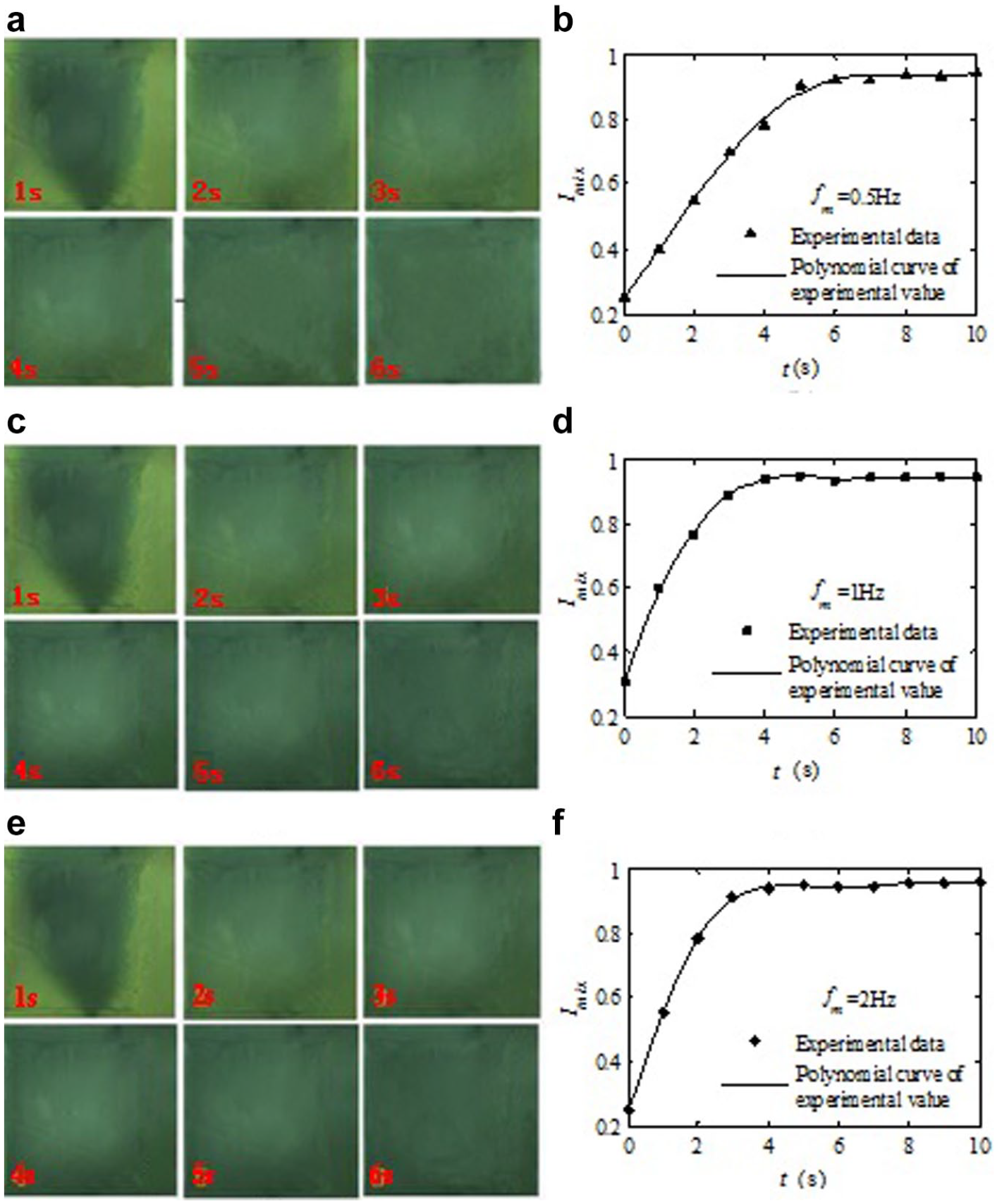
Pictures and mixing efficiency (Imix). (
Driving Air Pressure
The effect of the driving air pressure on the mixing efficiency has also been investigated in this study. The pressure range (10–30 kPa) can completely meet the needs of the commonly used pneumatic micromixer and will be used for the following performance tests. Three different driving air pressures, 10, 20, and 30 kPa, at 1 Hz of the driving frequencies are tested, and the results are shown in Figure 6 . When 5 s, the mixing efficiencies of three different driving pressures are 93.43%, 95.00%, and 94.31%, respectively. The results of the experiments show that when the driving air pressure is higher than 10 kPa, the value of the driving air pressure has little effect on the mixing efficiency of the proposed PDMS pneumatic micromixer. It is noted in Figure 6e that the defective background pixels of the square, which is the background of the actuated chamber, should be removed to reduce the calculation error.
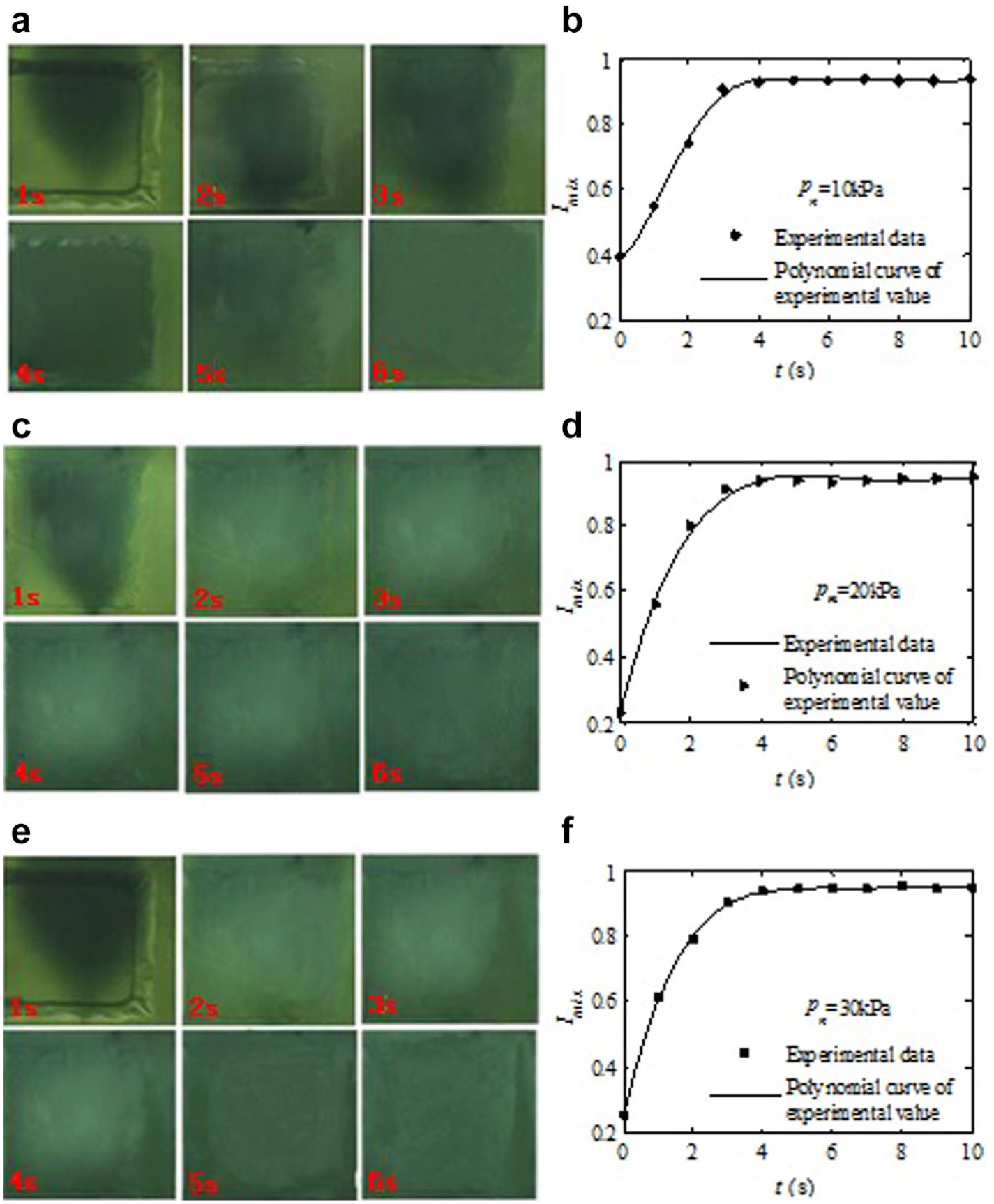
Pictures and mixing efficiency (Imix). (
Because the maximum displacement of the thin membrane is much larger than the depth of the mixing chamber under 10 kPa with the thin membrane dimensions of 800 × 800 × 40 μm, the effect of the surplus displacement on the mixing efficiency is negligible. The maximum displacement of the thin PDMS membrane under actuated pressures can be found in our previous studies;29,30 it is a function of not only the applied pressure but also its geometric dimensions and the fabricated process parameters of the thin PDMS membrane, such as ratio and cured temperature. However, when the air pressure exceeds 30 kPa, the mixing number needed is not obvious (three times shock). This is caused by the influence of the PDMS membrane; the effect of excess displacement under higher actuated pressure on mixing efficiency is negligible. It is noticeable that the mixed test in microscale is completed under the condition of low vibration frequency (less than or equal to 1 Hz). This is because the air control microchannel of the micromixer is relatively narrow and the flow resistance is relatively large, resulting in relatively long air filling and exhaust time.
Conclusion and Future Work
In this paper, a PDMS pneumatic micromixer with a simple structure and easy fabrication process was designed, fabricated, and successfully characterized based on the RGB color model. This micromixer is easy to apply and intuitive for biochemical analysis and biological fields requiring two or more samples to be mixed. The simplicity permits the design of multiple mixers integrated to microfluidic chips. The RGB color model-based digital image is used to quantify the mixing efficiency of different color reagents, and this easily understood, intuitive method can only calculate the mixing efficiency of color reagents. In addition, the pneumatic micromixer can also be used as a microreactor for noncorrosive effects of PDMS material, such as chemical reactions, organic synthesis, polymerase chain reactions, microorganisms, bacteria enrichment, and microbial testing.
Future work needs to be done to further study the mass flow characteristics of the mixing chamber according to computational fluidic simulation by Fluent software; the motivations are to obtain suitable actuated air pressures and driving frequencies, optimize the thin PDMS membrane thickness and depth of the mixing chamber, and further improve the efficiency of the mixing device. These mixing experiments are dominated by fluidic viscosity under microscale. In this paper, the experiment is conducted in a water-based solution, characterized by lower viscosity. The next step is how do obtain a high mixing efficiency for higher-viscosity solutions. The optimal actuated pressures, actuated frequency, and especially the size of the mixing chamber should be considered. These are all influencing factors for the proposed micromixer.
Footnotes
Declaration of Conflicting Interests
The authors declared no potential conflicts of interest with respect to the research, authorship, and/or publication of this article.
Funding
The authors disclosed receipt of the following financial support for the research, authorship, and/or publication of this article: This paper is financially supported by the National Natural Science Foundation of China (nos. 52005453 and 52075500), Key Scientific and Technological Project of Henan Province (no. 192102310046), and Dr. Scientific Research Foundation of Zhengzhou University of Light Industry (no. 2016BSJJ016).