
Abstract
A novel approach toward the needs of a versatile chip-based microfluidic system with unique properties and functionality is reviewed. Like for microarrays and in contrast to many existing technologies, the fluid handling is performed on the flat surface of a programmable chip, where fluidic tracks and functional blocks such as valves, dispensers, mixers, and sensing elements are chemically defined using standard lithographic techniques. The actuation of the fluid, the driving and addressing of the functional elements as well as possible sensors are based on electrically excited mechanical surface acoustic waves, propagating along the surface of a chip. Based on this acoustically driven microfluidic technique, a variety of different chips but also lab equipment has been devised, including a chip-based PCR reactor, microarray hybridization chambers, and noninvasive miniature mixers for cuvette and micro titerplate applications.
Introduction
Why is there a growing interest in microfluidic systems? Reducing the dimensions of macroscopic biological or chemical laboratories is advantageous for the following reasons. The small scale allows for the integration of various processes on one chip analogous to integrated microelectronic circuitry. Thus, manual handling, e.g., transferring reagents from one process step to the next, can be reduced. Such an integration is the prerequisite for a fully automated data management system covering all steps of a given chemical or biological process. Furthermore, the required reagent volumes are reduced thus saving both material costs and process time as many of the time-consuming amplification steps for biological substances can be omitted. Finally, the miniaturization results in enhanced precision by providing more homogenous reaction conditions and in shorter reaction times, as less sample volume is present at higher concentrations.
So far, in most of the microfluidic systems liquids are confined and moved in tubes or capillaries. Usually, the application of such systems is restricted to continuous flow processes. 1 Small amounts of liquid cannot be handled separately in tubes, as these need to be completely filled in order for the pumping mechanism to work properly. Such systems hence mimic laboratories using hoses and tubes rather than beakers and test tubes. Most of the work in macroscopic laboratories, however, is carried out as a batch process. A typical example is the mixing of two reagents or dissolving a substance in a liquid. A lab assistant would measure the required amounts in separate beakers, and then pour the substances in a third beaker while agitating with a magnetic stirrer.
Microfluidic devices for sophisticated lab applications usually comprise different components. First, the small amounts of fluids need to be confined to some kind of containers or reactors, holding specific amounts of the liquid. These containers and reactors are then connected via miniaturized tubes or channels, which in turn are usually operated by small pumps and valves. The whole system additionally needs to be interfaced to the outside world. The smallness of a microfluidic chip (tube diameters are typically of the order of 100 μm or less), ensures that only tiny amounts of reagents are needed for a chemical or biological reaction, on the other hand, however, it also causes complications that are not of relevance in macroscopic fluid-handling systems.
To start with, one has to regard the Navier-Stokes equation, describing the flow in a hydrodynamic system. It is a nonlinear equation in the velocity components, reading

where  is the velocity field of the flow, η the viscosity, and ρH the mass density of the fluid, p denotes the pressure that a fluid element experiences from its surroundings and
  is an externally applied body force driving the flow. The term p(
 · grad)
 thus describes the inertia of the fluid element and ηΔ
 marks the viscous term in the Navier-Stokes equation (1). The interaction between the fluid confined to a ‘lab-on-a-chip’ and the tube walls leads to hydrodynamic features that usually are comprised into a single number characterizing the flow behavior in a fluid, the Reynold's number Re, describing the ratio between the inertial and the viscous term:
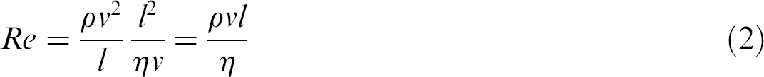
Here, l denotes a typical length scale in the system under consideration, for example the channel diameter. For a microfluidic system, Re is usually a small number, indicating the little importance of inertia in the problem. The most prominent consequence thereof and thus the most important difference to a macroscopic fluid volume is probably the lack of turbulent flows in a microfluidic system. The transition between turbulent and laminar flow is usually occurring at a threshold Reynold's number Re ≈ 2000. Given typical dimensions (l ≈ 10 μm), velocities (v ≈ 100 μm/s), and the material parameters of water (ρH = 103 kg/m3, η = 10−3 kg/ms), we end up at Re ≈ 0.001, a very small number, indeed. For a lab-on-a-chip application, this smallness usually causes severe problems. For instance, mixing of two fluids or stirring a liquid to enhance homogeneity or to speed up a chemical reaction, is a very difficult task for a purely laminar flow system. Also, pumping of a low Reynold's fluid is difficult, as the interaction of the fluid with the vessel walls mimics a high viscosity. These difficulties need to be solved.
Experimental Details
In this article, we wish to review a novel approach toward the needs of a microfluidic lab-on-a-chip. We show that flow in a microfluidic system can be induced by the interaction of the fluid and so called surface acoustic waves (SAW), propagating at the surface of a solid chip. The driving force behind this interaction and the resulting acoustically driven flow is an effect called ‘acoustic streaming’. Acoustic streaming is a consequence of the (weak) pressure dependence of the mass density ρH of a fluid, leading to a nonvanishing time average of the acoustically induced pressure. Acoustic streaming is a well-known effect for a long time in macroscopic, classical systems. 2
Here, we report on SAW streaming induced in a fluid residing directly on top of a planar chip and in some alternative geometries. SAW have been first described in combination with earthquakes. 3 Meanwhile, reduced to the significantly smaller nanoscale, they found their way into much friendlier fields. SAW devices are widely used for radio frequency (RF) signal processing and filter applications and became a huge industry in mobile communication. SAW devices have been around for years in communication circuitry—every cell phone has filters using the effect. SAW are especially convenient to excite on piezoelectric substrates. Such materials undergo a defined deformation if subjected to an electric field, and vice versa produce an electric field if being deformed. The reason behind this is the lack of inversion symmetry of the respective crystal structure. A SAW of a well defined wavelength and frequency can be excited on such a piezoelectric substrate if a specially formed pair of metal electrodes is deposited on top of the substrate. Such electrodes are usually referred to as interdigitated transducers (IDT). A high frequency signal applied to such an IDT is then converted into a periodic crystal deformation and if fed with the right frequency

a monochromatic and coherent SAW is launched. Here, v SAW denotes the sound velocity of the respective substrate, and the wavelength λ is given by the lithographically defined periodicity of the IDT. All physical quantities related to the SAW like material deformation, stress and strain, as well as the piezoelectric fields, and potentials associated with the mechanical part of the wave decay in an exponential manner with the substrate and vanish at approximately one wavelength depth. Typical wavelengths of technically exploited SAW range from about λ = 30 μm at f ≈ 100 MHz down to λ = 0.5 μm at f ≈ 6 GHz. If a second IDT is placed downstream the substrate surface, a so-called delay-line is formed. An electrical high frequency signal fed into one of the transducers is converted into a surface sound wave, which travels along the substrate surface until it reaches the receiving transducer. There, it is reconverted into an electrical high frequency signal. Both transducers, their design, and the substrate properties thus act as a high frequency filter with a predetermined frequency response. They are lightweight, relatively simple and low cost, and can be produced very easily, which explains their massive use in high frequency signal processing like mobile telephones.
In the recent past, however, SAW have also been used to act in a completely different way than for filtering and signal processing just by converting electrical signals into mechanical vibrations and vice versa. Nearly 20 years ago, we introduced SAW to study the dynamic conductivity σ(w,k) of low-dimensional electron systems in high magnetic fields and at low temperatures. It turns out that the interaction between a SAW and the mobile charges in a semiconductor is strong for very low sheet conductivities as they are observed, e.g., in the regime of the quantum Hall effect. 4 However, SAW cannot only be used to probe the properties of quantum systems, but also to deliberately alter some of them. SAW represent a spatially modulated strain and stress field accompanied by strong electric fields in a solid, and propagating at the speed of sound. Such an interaction between SAW and the optical properties of a semiconductor quantum well led us to the discovery that photogenerated electron hole pairs in a semiconductor quantum well can be spatially separated under the influence of a SAW mediated electric field. This, in turn, has an enormous impact on the photoluminescence (PL) of the semiconductor. We were able to show that the PL not only is quenched under the influence of a SAW, but also can be re-established at will at a remote location on the sample and after a certain delay time. 5 Further studies include the acoustic charge transport and the creation of dynamically induced electron wires, 6 as well as the study of nonlinear acoustic interaction with low dimensional electron systems in semiconductors. 7
The piezoelectric effect however is usually only a small contribution to the elastic properties of a solid whereas most of the energy propagating in a SAW (usually more than 95%) is of mechanical nature. Hence, not only electrical interactions as described above, but also mechanical interactions are a possible scope for experimental investigations. Having wavelengths of a few microns and amplitudes of about only a nanometer, however, the forces and electric fields within the SAW ‘nanoquake’ are sufficient to have a macroscopic effect. Any piece of matter at the surface along the way of a SAW experiences their vibrating force. Viscous materials like liquids absorb a lot of their energy. It turns out that the interaction between a SAW and a liquid on top of the substrate surface induces an internal streaming, and, as we will point out below, at large SAW amplitudes this can even lead to a movement of the liquid as a whole. 8 In Figure 1, we depict the basic interaction between a SAW and a fluid on top of the SAW carrying substrate. The SAW is approaching from the left and entering the fluid covered region (represented by a droplet in this case) of the chip. There, it becomes attenuated by a viscous damping mechanism, which leads to the excitation of a sound wave in the fluid itself. Phase conservation requires that this sound wave is entering the fluid under an angle ΘR, very much like a diffracted beam in optics. SAW streaming as described above then leads to an internal streaming pattern within the droplet, the exact shape of which is determined by ΘR and the geometry of the fluid volume.
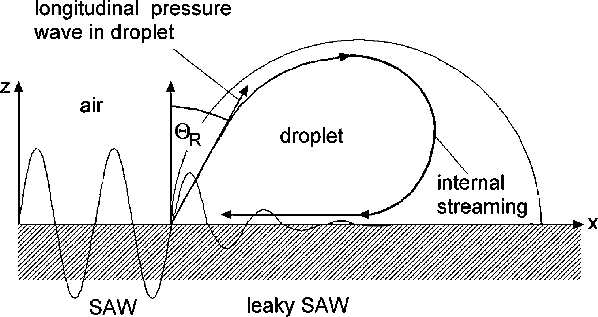
Sketch of the acoustic streaming acting on a small droplet on the surface of a piezoelectric substrate. The acoustic energy is radiated into the fluid under an angle ΘR, leading to internal streaming in the small fluid volume.
Acoustic Mixing
The internal streaming as shown in Figure 1 can be very efficiently used for mixing smallest amounts of fluid. In Figure 2, we show a series of two snapshots, about half a second apart, taken for a 50 nL droplet. Here, some fluorescent dye had been deposited at the chip surface just before the water droplet was placed on top. Not only is the dye dissolved by the internal streaming, but also distributed across the whole volume of the droplet. It should be noted at this point, that the SAW induced streaming still is laminar, as the Reynold's number is so small. The complex flow pattern, however, strongly supports complex material folding lines, which in turn facilitate a quick mixing. 9 Moreover, by switching the SAW frequencies and or directions during the mixing, different material folding lines are generated which further improve mixing.
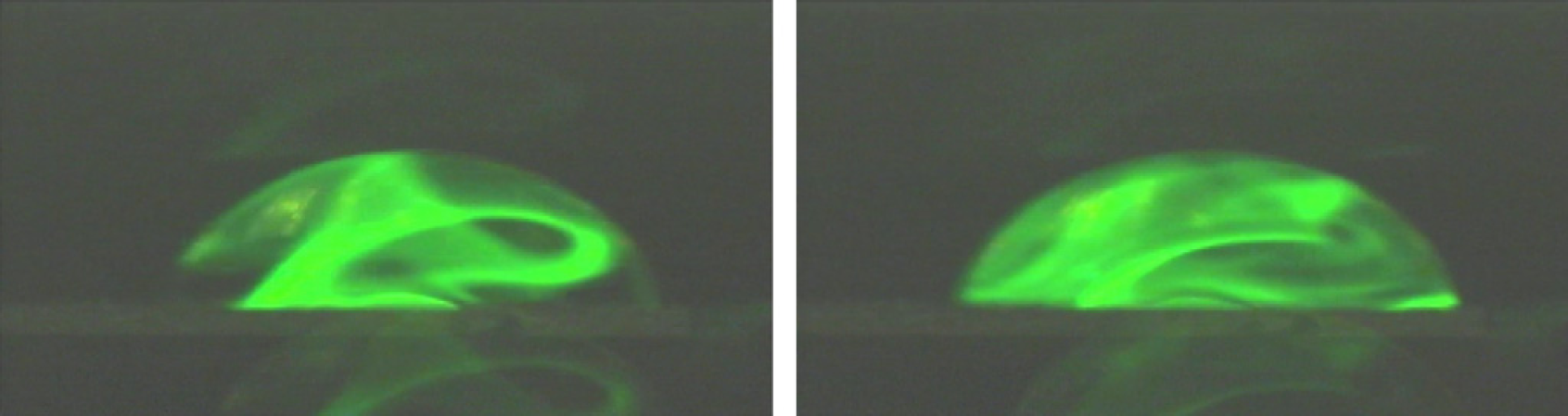
SAW induced internal streaming in a small water droplet (side view, approx. 50 nL). A dried fluorescent dye on the surface of the chip is dissolved by SAW agitation, and rapidly fills the whole droplet volume.
This SAW driven mixing in small amounts of fluid also works in different geometries. For instance, a liquid filled capillary gap as being formed between two cover slips, can be very efficiently mixed and stirred this way. Based on this approach, a microarray hybridization chamber for genetic and proteomic assays has recently been brought into market (“SlideBooster” by Advalytix AG, Brunnthal, Germany). The acoustic agitation during the hybridization of a microarray assay not only reduces the hybridization time significantly, but also improves the homogeneity of the fluorescent labelled spots on the microarray. 10
Coupling the SAW through the bottom of a cavity consisting of a different material as the SAW chip is also possible. In Figure 3, we want to show the results for SAW streaming in a single well of a 96-well microtiter plate (MTP). In Figure 3(a), we depict the geometry of the arrangement. The SAW chip is placed underneath the MTP, where the acoustic energy is coupled to the MTP by using a coupling fluid. The photograph inset shows a narrow sound beam being injected into the fluid, where it has been visualized by a little bit of ink in the water. After some time, the ink is distributed within the whole volume of the MTP well. Switching the power and the frequency of the SAW during mixing leads to a homogeneous distribution of the ink (Fig. 3(b)). In principle, each well or groups of neighboring wells of the MTP can be addressed separately using this technique. This contactless SAW mixing works especially well for even smaller wells, like in a 384-well MTP or a 1584-well MTP.
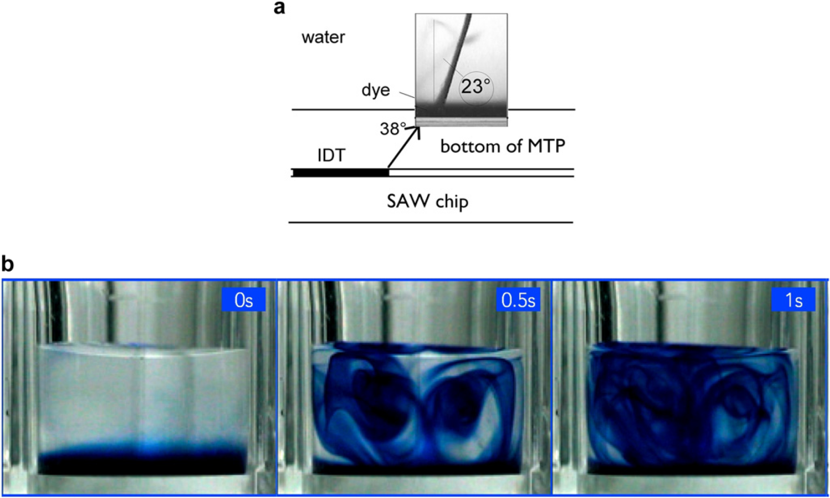
(a) SAW coupling through the bottom of a microfluidic chip (in this case polystyrole) into the fluid in a microfluidic channel on top. Depending on the different sound velocities in the different media, the diffraction angle changes. In the water, the angle of diffraction has been visualized by acoustically pumping a small amount of dye, leading to the sharp jet in the inset photograph shortly after switching on the SAW. (b) Series of snapshots of the SAW mixing in a 96-well MTP at somewhat later times as indicated. The SAW streaming leads to a homogenous distribution of the ink within the well.
Droplet Actuation
For somewhat higher SAW amplitudes, the acoustic streaming effect leads to a strong deformation of the liquid surface and a momentary asymmetry in the wetting angles left and right with respect to the SAW impingement (Fig. 4). Especially for small droplets, this leads to a movement and an actuation of the whole droplet into the direction away from the SAW. As SAW can be electrically excited using a high frequency signal and an IDT, one can regard an IDT on a piezoelectric substrate as an integrated nanopump. Moreover, using a chemical surface modification, one can define hydrophobic and hydrophilic regions on the chip surface, acting as anchors or fluidic tracks for small droplets. As an example for the versatility of this approach in terms of lab-on-a-chip applications, we show in Figure 5 a series of snapshots of a programmable microfluidic chip with integrated planar pumps. Here, we have used three different droplets of different chemicals that exhibit a color change when merged and mixed. It should be noted that while the droplets are actuated and eventually merged, in their interior the SAW streaming leads to extremely fast chemical reactions as compared to a diffusion-only driven process.
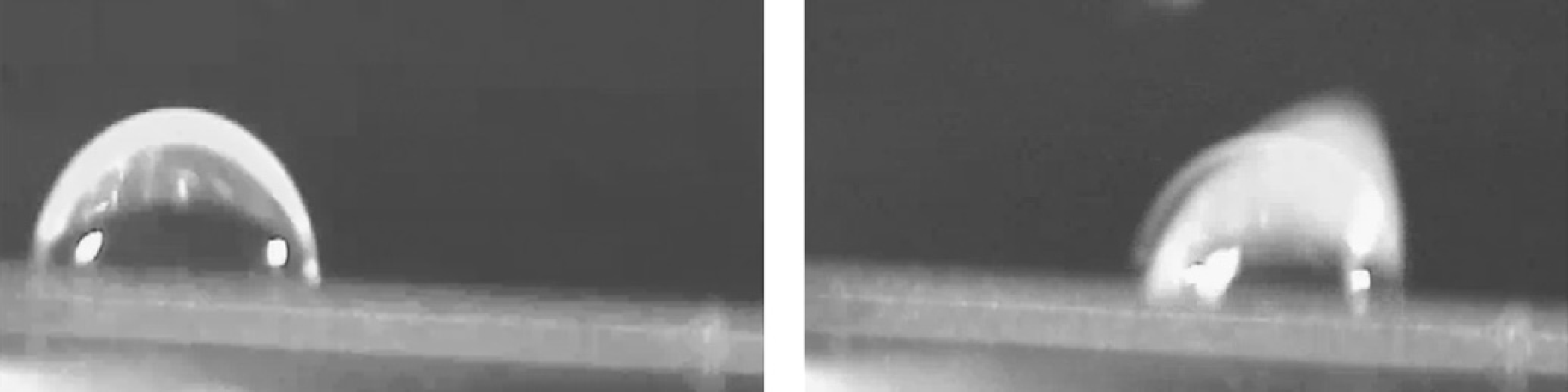
Side view of a small droplet (ca. 50 nL) on the surface of a piezoelectric substrate. Left: droplet in rest, note the wetting angle of about 90°, which has been obtained by a hydrophobic treatment of the surface. Right: droplet being “hit” by a SAW impinging from the left. The acoustic radiation strongly deforms the droplet shape. This leads to a momentary asymmetry of the wetting angles of the droplet.
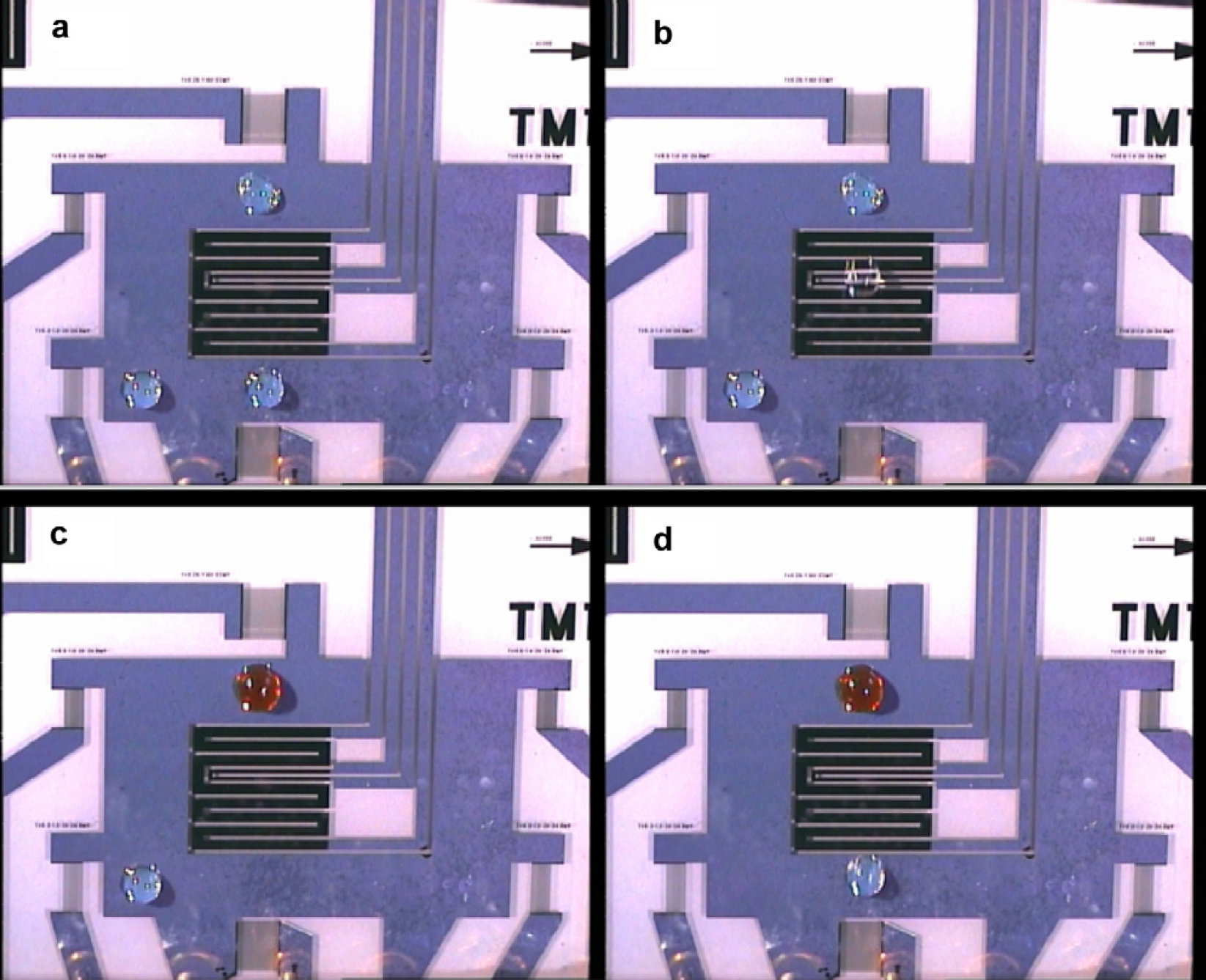
A SAW driven microfluidic processor. Three droplets (approx. 100 nL each) are moved ‘remotely controlled’ and independently by the nanopumps. (a)–(d) represent a series of subsequently taken snapshots to visualize the movement, and the ‘nanochemical reactions’ occurring when the droplets are merged and mixed by the action of the surface wave. The chip not only contains the nanopumps and the fluidic environment, but also the center additional real estate like sensors and heaters.
PCR on a Chip
Having a completely programmable microfluidic chip at hand, one can aim toward more complex assays like polymerase chain reaction (PCR) on a chip. 10 Here, however, comparably high temperatures are involved during the protocol. Such high temperatures are not compatible with the ‘open geometry’ of our droplet-based fluidics. To avoid evaporation—especially during the 95 °C cycle of a PCR process—we cover the aqueous sample solution with a mineral oil layer. The sample contains all the ‘PCR-mix’ including template, primers, and polymerase for a successful amplification of a small amount of genetic material. The sample volume in this case is well below 10 μL. To confine both the oil as well as the aqueous solution at the same chip surface, a sophisticated surface chemistry is required. 8,11 The result is a ‘virtual liquid test tube’ as depicted in Figure 6. Here, the sample droplet has a red color for better visualization. As the programmable biochip is fabricated using standard planar lithographical technology, it is an easy task to also include additional functional elements like thermometers and heaters. The optical transparency and the lack of self-fluorescence of the substrate materials used further adds valuable for this lab-on-a-chip application. 11 In Figure 7, we show a typical PCR chip as described above. In Figure 7(a), we depict a top view of the chip. In the lower right corner, an oil droplet is seen, with four different sample droplets, each holding a different sample. Figure 7(b) shows a side view of the chip with the tiny droplet on the upper side. From below, an optical system (see Fig. 7(c)) is used to monitor the progress of amplification using an intercalating dye. For details of the PCR protocol, the sensitivity of the technology, and typical experimental results, we refer the reader to the work of Z. Guttenberg et al. 11 as this is beyond the scope of the present manuscript.
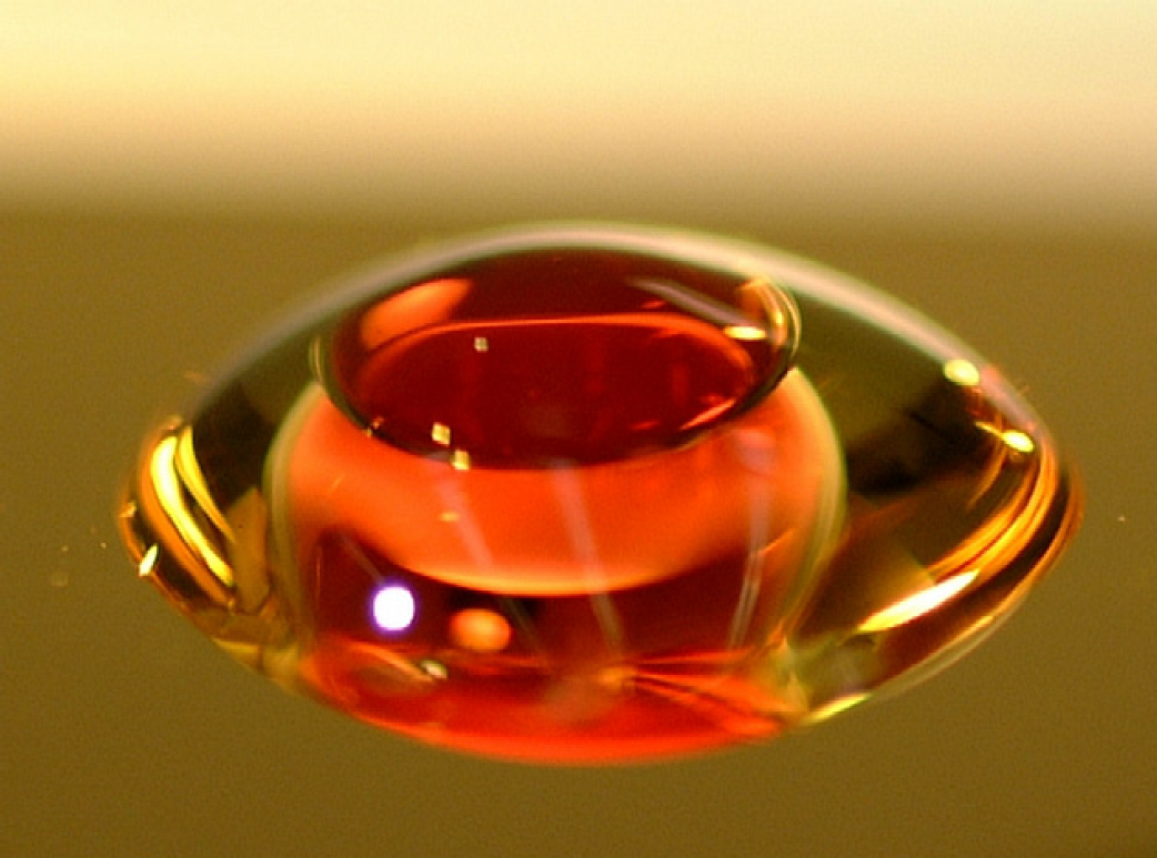
‘Virtual liquid test tube’ for high temperature application of the planar SAW driven fluidics. To avoid evaporation of the aqueous sample solution (red), the droplet has been covered by a thin mineral oil layer. Both represent a fluid test tube for further processing of the sample.
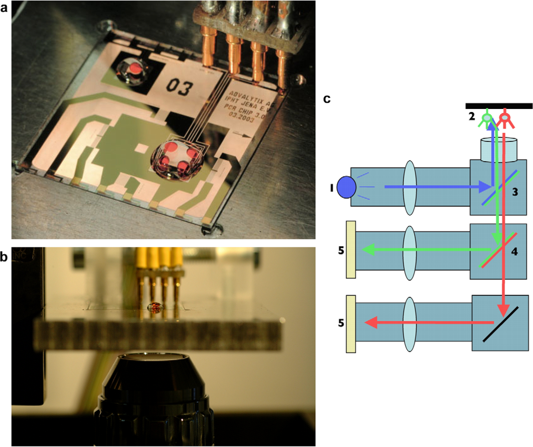
Programmable microfluidic biochip for multispot PCR. (a) Top view: the sample solution in red is covered by a mineral oil layer to prevent evaporation at elevated temperatures. Apart from SAW driven nanopumps for the fluid actuation, the chip also hosts a heater and a thermometer. The chip is connected to the outside via pogo contacts. (b) Side view of the chip. Underneath the transparent piezoelectric substrate, a microscope objective is seen for fluorescence monitoring (c) of the PCR progress using an intercalating dye.
Summary
In summary, we described a novel and unconventional technique to manipulate smallest amounts of liquid on a chip. Using SAW on a piezoelectric substrate, we are able to actuate individual droplets along predetermined trajectories, or induce acoustically driven internal streaming in the fluid. This internal acoustic streaming can efficiently be used to agitate, mix, and stir very small liquid volumes, where the low Reynold's number usually only allows for diffusive mixing. We described several applications of the SAW driven microfluidics, including a nanomixer for micro array applications, a contactless mixer for MTPs, a programmable microfluidic chip for droplet-based assays, and finally a chip performing high resolution microliter PCR. The technique is equally well suited to actuate or agitate small amounts of liquids either in closed volumes or in an open, droplet-based geometry. Each of the approaches has its clear advantages, but also disadvantages. Droplet-based fluidics is certainly well suited to handle smallest amounts of fluids without the risk of cross contamination etc. High temperature processes, however, require additional means like covering the droplet with an oil film. SAW pumping, mixing, and stirring on closed volumes is advantageous over many other pumping schemes as the pumps are easily incorporated into most of the existing microfluidic device or lab-on-a-chip. The combination of the SAW actuated droplet-based fluid handling and SAW driven fluidics in closed volumes opens a wide field of many different applications, a few of which I had the pleasure to present in this article. Many more applications, and many more visualizations of the technology described above can be looked up on Advalytix' website http://www.Advalytix.de.
Acknowledgments
This work would have been impossible without the combined efforts of many people involved, both at the University of Augsburg, as well as at Advalytix AG. Some of them are listed in the references below, others unfortunately may remain unaccounted for in this article. Financial support was provided by the German minister for research and technology (BMBF), the Bavarian Science Foundation, and the German Science foundation DFG All these contributions are gratefully acknowledged.