
Abstract
We present a method of creating three dimensional microfluidic channel networks and freestanding microstructures using liquid phase photopolymerization techniques. The use of liquid phase microfabrication facilitates the creation of microstructured devices using low-cost materials and equipment. The ability to add multiple layers allows for complex geometries and increases the functional density of channeled devices. The multilayer technique provides a method of interconnecting layers or combining separate layers to form a truly integrated multilayered microfluidic device, as well as a means of forming multilayered freestanding structures. Because this method is based on the fundamentals of microfluidic tectonics (μFT), all components (valves, mixers, filters) compatible with μFT can be integrated into the multilayer channel networks.
Introduction
Many factors are important in the fabrication of microdevices, including channel dimensions, component integration, fabrication time, macroscale integration, and multilayer capabilities. Traditional methods of creating microstructures include micro-machining, soft lithography, in situ construction, injection molding, and laser ablation. 1 Several of these methods create structures out of solids (micro-machining, injection molding, and laser ablation), while others use viscous polymers (soft lithography) molded from solid structures. 1 –3 An important part of any fabrication technique is the ability to pattern microstructures and build multiple layers of channel networks or three-dimensional components. While this can be done using the methods described above, any additional layers require increased fabrication time, sophisticated bonding techniques, and expensive alignment aides. In addition, current methods of microfabrication are expensive, and an additional layer can greatly increase the overall cost. In situ construction, as defined here, describes a fabrication method using a liquid phase prepolymer to create microstructures inside a cavity. While other methods of in situ construction have been described, 4,5 the techniques described here are based on the methods of microfluidic tectonics (μFT). 6,7 The materials used in μFT are inexpensive, making prototyping and disposability practical. The techniques to create multilayer channel networks and structures presented here make μFT a versatile method of device fabrication.
Microfluidic tectonics is a fabrication technique that uses UV light and film output photomasks to pattern a liquid phase photopolymer contained within a shallow cavity. Ultrarapid prototyping (URP) uses μFT techniques to create microfluidic devices 8 using commercially available products and low-cost materials. However, many applications require components that consume more space than is available within the constraints of a one-layer device or require geometry only available with the addition of multiple layers. The ability to add layers increases the functional density, expands the channel geometry possibilities, and adds little to the overall size of the device. A layered device needs to have the capability of selectively interconnecting otherwise independent channel networks. The techniques presented here include the ability to interconnect layers or keep the layers separate. Unlike the methods of stacking layers made from other materials like polydimethylsiloxane (PDMS), silicon, or glass, no additional bonding step or special surface treatment is required. In addition, microstructures have been fabricated using microstereo lithography and two-photon absorption, 9,10 but these techniques often require expensive equipment such as lasers or computer controlled stages. The structures presented here can be fabricated using the same low-cost materials and methods as the microchannels.
Experimental
To construct a basic one-layer device using the methods of URP, 8 a prepolymer solution (containing 95% isorbornyl acrylate to 5% tetra ethylene glycol dimethacrylate, and DMPA (3 wt %), a photoinitiator) is contained within a shallow cavity and exposed to UV light through a mask. The unpolymerized liquid is flushed out, resulting in a channel network. The resolution of the channel structures is given in more detail in previous work. 8 The shallow cavity consists of a polycarbonate film top (thickness approximately 170 microns) with adhesive gasket sides (HybriWell HBW-UVTP, Gracebio Labs, Bend, OR), which is attached to a microscope slide. The adhesive gasket maintains the cavity height, (∽250 μm), and the flexibility of the polycarbonate top accommodates the inherent shrinkage of the polymer solution during polymerization (approximately 10%). When fabricating additional layers, the polycarbonate tops are punched using a Sensi-Press (Micromark, Berkeley Heights, NJ) and 1/32” punch/die set (Roper Whitney, Rockford, IL) as shown in Figure 1a. These interconnected holes are in addition to the filling ports already present on the HybriWell. For alignment purposes during the punching process, the mask used for each layer, including holes for punching, is printed on window decal material (Xerox, Rochester, NY) on a low-resolution printer. The decal material sticks to the polycarbonate tops and serves as a simple method for alignment by providing the punching pattern. The two HybriWells that require punching have pegs inserted into three filling ports to hold them together during the punching process (Fig. 1b). The layers that require the same punched pattern are punched simultaneously, minimizing hole alignment error since the holes will automatically align when layered (Fig. 1b). The decal material is then easily removed (Fig. 1c) and does not leave residue or damage the HybriWell top. The resulting HybriWells are now punched with perfectly aligned holes ready for channel fabrication (Fig. 1d).

A Sensi-Press (a) is used to punch holes in the polycarbonate top. Window decal material is printed with alignment holes. The decal is placed on top of two HybriWells held together with pegs, and the layers are then punched simultaneously (b). The decal is easily removed after punching (c) and the resulting HybriWells are now punched and ready for use (d).
The first punched layer is attached to a microscope slide, and the resulting cavity is filled with prepolymer. The layer 1 mask is placed on top, and the device is exposed to UV light (intensity is 18–24 mW/cm2 at 365 nm) for 12s, forming the first layer channel network. Before attaching the next layer, the first layer channel is attached to a vacuum for up to 5 min to remove any unpolymerized monomer, flushed with water, and dried. The channel network is then filled with a dyed solution (Fig. 2a). The dyed solution (glycerin with several drops of dye) and prepolymer material are immiscible, and the dyed solution prevents any leakage of prepolymer into the previously formed channel network. If leakage does occur, it is easily visible before polymerization. This is an important feature, because if prepolymer is present in the network during exposure of the second layer, it can lead to clogging of the first layer channels. The second punched layer is now attached on top of the first layer, and the process is repeated as before. After layer 2 has been exposed and cleared, the entire new channel network is flushed and filled again with the immiscible solution (Fig. 2b). In this manner, any number of layers can be fabricated, one on top of the next. Each layer takes less than 15 min to fabricate. The top layer is not punched and completes the layered device (Fig. 2c).

Layer 1 is shown filled with a dyed immiscible fluid (a). The prepolymer and water or glycerin do not mix during exposure of the subsequent layers (b) and (c). Mask designs of the channel networks for each layer are shown above the figures. Channel widths are 800 μm. Scale bars shown are approximately 5 mm.
This method can be used to integrate filters made from a polycarbonate thin film with various pore sizes (GE Osmonics, Minnetonka, MN) into a layered device. Figure 3a shows a schematic drawing of the filtering channel network. The filters are simply laid on top of the first layer and the edges are wetted with prepolymer. The area is then exposed to UV, with a mask over the opening into the channel underneath, effectively gluing the filter in place. The mask prevents any prepolymer from plugging the filter area over the channel. The upper channel is then built around the filter using the same layering technique as described earlier. A filtering device is shown in Figure 3b, with multiple beads trapped in the filter area.

A schematic (a) showing a side view of the filter incorporated into a two-layer device. A photo (b) is shown of an actual device with beads trapped in the filter. The circle outlines the incorporated filter (13-mm outer diameter). The polymerized filter area is approximately 6 mm.
In addition to forming three-dimensional channel networks, a variation of this technique can be used to create freely moving microstructures such as gears and simple gear trains. To create these types of structures, the first cavity is formed on top of a flexible substrate such as a plastic microscope slide. The cavity is filled with photopolymer and exposed to UV light as described above. Next, the top is removed, leaving both the solid polymer structures and the remaining prepolymer on the slide. For double-layered structures, a second cartridge with a thicker gasket is then placed on the slide with the original structures and filled with additional prepolymer. The mask for the second layer is visually aligned with the previously formed structures and the second layer is exposed. This process can be repeated until the desired number of layers has been achieved. The height of each layer is determined by the thickness of the gasket used in that iteration. Once all layers have been formed, the remaining liquid is flushed away with water. Because of the rigidity of the photopolymer, the flexible substrate can be bowed, and the structures easily removed as they delaminate off the substrate (Fig. 4a). Eliminating the polycarbonate top and using the photomask as the top surface can give better resolution. More complex structures that have larger structures fabricated on top of smaller structures are possible by using a slightly modified technique. After the first-layer structures have been formed, the remaining monomer is flushed out of the cavity using a vacuum and water. The entire device is then heated and filled with liquid low-temperature wax (Fisher Scientific, Pittsburgh, PA). Cooling the slide solidifies the wax, leaving the polymer structures surrounded. At this time the polycarbonate top is removed, leaving both wax and polymer structures on the substrate, and the process is repeated as before. The wax prevents the prepolymer from entering the previously formed layers, thus allowing much more flexibility in the geometry of the structures (Fig. 4zb).

A freestanding dual gear is shown held by tweezers (a), and a scanning electron microscope (SEM) image of another dual gear is shown (b). The smaller gear in (b) was fabricated before the larger gear.
Results and Discussion
The three-layer device shown in Figure 5 shows layers 1 and 3 interconnected to form a serpentine channel that wraps around layer 2. The serpentine channel also serves as a passive mixer. 11 A possible application of this device is to control the temperature of the central channel by circulating warm or cold fluid in the serpentine channel. This type of channel network can only be fabricated using multiple layers. Alignment of the through holes of different layers is critical (during punching and fabrication), and the use of the window decal material acts as a simple alignment aide during punching. The temporary adhesive nature of the window decal material allows adhesion to the HybriWell top and prevents movement of the alignment aid during punching. The window decal removal leaves no residue, and the added thickness minimizes deformation at the edges of the holes due to the tolerance of the punch and die used.

A schematic (a) is shown of a three-layer device. Layers 1 and 3 are connected through layer 2 but do not interact with the layer 2 channel. Layers 1 and 3 form a serpentine channel around the center channel (b). A close up of the device (c) shows blue and yellow dye flowing into the bottom layer and mixing in the passive mixer that is wrapped around the middle layer (red dye). Individual layers are shown in Fig. 2. Scale bar shown is 2 mm.
Unlike other methods, no bonding step is required to connect each layer. The adhesive nature of the photopolymer adheres the layers during channel formation, while the adhesive gasket maintains channel height. The methods described here can be used with many UV adhesive polymer solutions. The ability to introduce 3D geometries allows the fabrication of a wide variety of functional devices. Previously, 3D serpentine channels have been formed in PDMS and silicon. 11,12 This geometry, shown in Figure 6a, is easily repeated in μFT using layering techniques. The layering method presented here requires less time (each layer takes approximately 15 min), no sophisticated bonding methods, and no clean room facilities. Mixing starts to occur within the first few bends in the channel (Fig. 6b).

A schematic is shown of a 3D serpentine chaotic mixer (a). Layers 1 and 2 are connected to form a micromixer with blue and yellow dye. The streams start to appear green by the first turn in the channel (b). Scale bar shown is approximately 2 mm.
The 3D layering method was used to integrate porous polycarbonate filters into the channel network. Figure 7 shows micrographs of the filtering channel network. A syringe pump was used to flow a solution with two bead sizes (pink-3 micron and yellow-45 micron in size) at a rate of 10 ml/min through the filter. As the solution of 3 micron (pink) and 45 micron (yellow) beads flow through the upper channel and through the filter, the 3 micron beads pass, while all of the 45 micron beads stay on top of the filter. The 5 micron filter allows the smaller beads to pass, but as more and more beads are introduced, the smaller beads start to clog the filter. Eventually the filter became completely filled with the smaller beads (Figure 7c).

A solution containing both 3 micron and 45 micron beads is allowed to flow through the filter (a). As the beads start to block the filter, they start to become more visible (b). The 45 micron beads are shown building up on top of the filter (c). A picture of the device is shown for scale (d). Flow rates were 10 mL/min.
Using this method to fabricate microstructures, any shape that can be drawn on a high-resolution graphing program can be made into small parts for easy prototyping. A gear shaft is shown in Figure 8a that depicts well-defined teeth over a large area. A close-up of one of the teeth in a single gear shows smooth walls on the surface of the tooth (Fig. 8b).
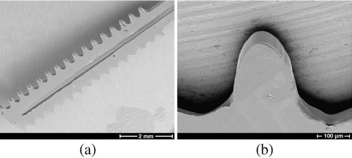
SEMs are shown of the polymer microstructures: a gear shaft (a), and a close up of one of the gear teeth (b).
Conclusion
An ultrarapid method of fabricating stacked microchannel layers and microstructures has been presented. The μFT platform allows easy integration of other components such as mixers, filters, and valves, while also allowing different channel geometries. The process is fast (each layer takes less than 15 min) and does not require clean room facilities. The added channel geometry can be used to create components such as 3D passive mixers needed for chemical or bioassay development. This technique also allows the incorporation of commercially available filters to be used for separating beads in solution. The added functionality of this technique has been used to fabricate devices for bioassay development. 13 The nature of the liquid prepolymer is easily applied to the fabrication of multilayered structures (gears) that can quickly be fabricated. No bonding is required between each layer and complex geometries can be realized.
Acknowledgments
We gratefully acknowledge support from DARPA-MTO under grant number F30602–00–3–0570. (Program manager: Dr. Michael Krihak).