
Abstract
Anovel in-plane microfluidic mixer based on fluidic discretization using vortex micropumps integrated in an optically transparent microfluidic substrate is presented in this article. The design, fabrication, simulation, and experimental results are described of this integrated micromixer. The basic working principle of the discretized fluidic mixer is to manipulate fluids as discretized volumes and inject them to an expansion chamber. Due to increase interfacial surface area of the discretized fluid “chunks,” the diffusion between these fluids can be completed in a shorter time, and the fluids can be mixed instantly without additional external energy. A numerical simulation was performed to emulate the flow field and mixing phenomenon to understand the results obtained by various flow experiments. Experimental results of discretized mixing have been successfully shown to have almost an ideal mixing performance and shown reasonably good match with the simulation results. Moreover, a dimensionless governing parameter (mixing index) was used to estimate the mixing performance in our system. This parameter is shown to be useful for the design and analyses of discretized mixing systems. Because this discretized mixing system requires simple mechanical structures, it provides flexibility for integrate with other microfluidic components. Also, optically transparent and biocompatible material was used to fabricate the microfluidic system, hence this micromixing system could be used to develop future fully automated biomedical and chemical “lab-on-chip” systems.
Introduction
Microfluidic mixing plays an important role in biochemical analysis systems. For instance, to achieve accurate diagnosis results in a reasonable period of time, efficient and precise mixing of reagents is required. However, due to the low Reynolds number flow regime in micro-scale fluidic environment, mixing is typically dominated by diffusion instead of turbulence. But, mixing by diffusion in microfluidic systems is a relatively time-consuming and inefficient process. Hence, to achieve mixing in a fastest possible time becomes one of the most challenging tasks in microfluidic systems.
In order to enhance the mixing in microfluidic systems, some special mechanisms must be used to manipulate fluids for increasing the interfacial surface area, which allow the diffusion be completed in a shorter time. Some research groups have developed micromixers using moving parts for generating vortex flow or varying pressure gradient, which are called active micromixers. Several active mixing methods have been developed, such as ultrasonic, 1 magnetic microstirrer, 2 and bubble-induced acoustic mixing. 3 These micromixers require the use of external energy and most of the active mixing methods are relatively complicated in fabrication and incompatible with other in-plane fluidic devices. Also, because of their relatively high fabrication cost, they are often not suitable for disposable systems. However, the advantage of active micromixers is that they can provide an excellent mixing performance in a short time. On the other hand, micromixer using no energy input except the fluid driving mechanism (pressure head or pump) is called passive micromixer. It has the advantages of no complex control units, no additional input energy, and low fabrication cost. Passive micromixer usually splits the bulk unmixed fluids into several substreams and reunifies them to mixed fluids. Because of the low Reynolds number, mixing of substreams is relied on diffusion between their interfacial areas. So, increasing the interfacial area of the substreams can improve the mixing performance and efficiency. In some literatures, three-dimensional microchannels are used for splitting and reunification of fluids to increase the interfacial areas of substreams. 4 -6 These three-dimensional passive micromixers can achieve fluid mixing at high flow rate in a short time. However, fabrication of three-dimensional structures requires multilayer processing, such that the integration of other in-plane fluidic devices may not be feasible.
In this article, we propose a novel in-plane micromixing method using fluidic discretization. The principle essentially is to manipulate source fluids into “discretized elements,” which are then pumped into an expansion chamber to increase the interfacial surface area of these “elements.” Hence, the diffusion between fluid elements can be completed downstream in a shorter time. Because fluid mixing is generated by “discretized elements,” this micromixing is called “discretized micromixing.” A microfluidic system, integrated with two vortex micropumps, an expansion chamber and connecting microchannels, was used to demonstrate this discretized mixing process. Two vortex micropumps were used to “discretize” fluid flow. Numerical simulation and experimental results of this micromixing phenomenon will be described in this article. Due to its simple in-plane structure and highly integrable characteristics, the integrated system described in this article could be further developed and integrated with biochemical analysis systems, especially for applications where automated fluid pumping.
Vortex Micropump
The fluid manipulation of our proposed microfluidic mixing system is driven by vortex micropumps. Detailed fabrication and analytical modeling results for these micropumps are discussed in Refs. 7,8. The vortex micropump uses kinetic energy to move fluid using an impeller and a circular pump chamber. The fundamental design concept is illustrated in Figure 1. The fluid enters the pump near the center of the impeller and is moved toward to the outer surface of the pump chamber by rotating motion of the impeller. Because of the boundary of the pump chamber, fluid is guided to enter a connecting microchannel and a pumping flow is created. Because the generation of pumping flow is due to the rotating motion of the impeller, by changing the rotational speed of the impeller, pumping flow rate can be controlled smoothly.
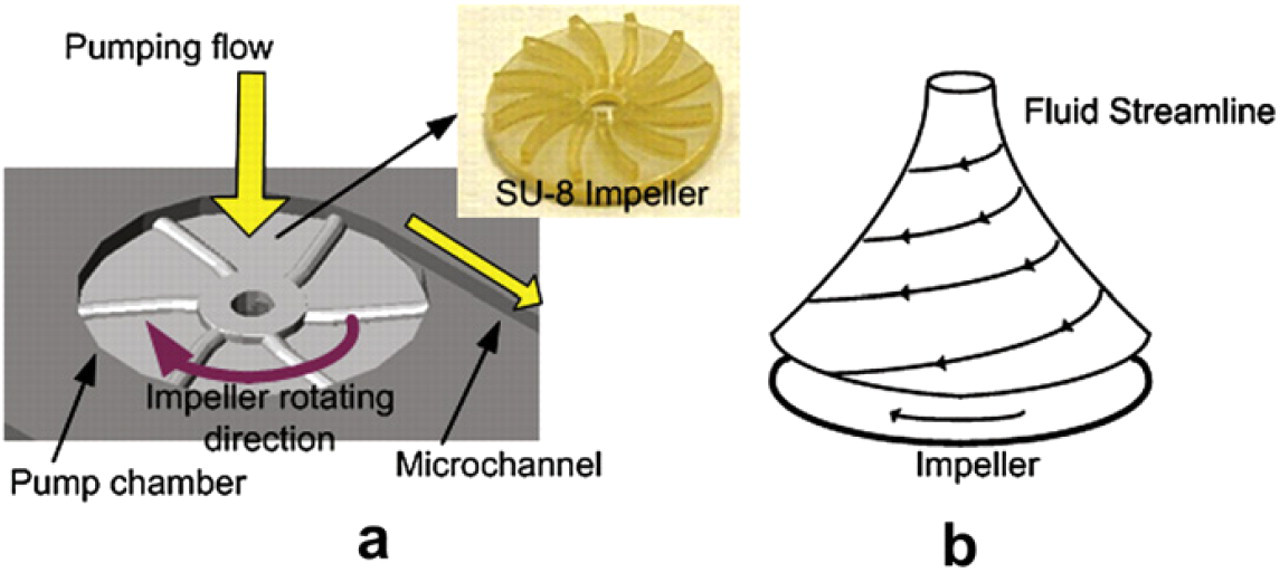
(a) Illustration of the vortex micropump working principle. (b) Fluid streamline inside the pump chamber.
Because the materials used in microfluidic devices are required to be optically transparent and biocompatible for bio-optical detection and chemical applications, we used polymethyl methacrylate (PMMA) as the structural material. The vortex pump consists of a pump chamber, connecting microchannel and a micro impeller. The micro impeller fabricated by SU-8 photoresist is placed inside the pump chamber. When fluid enters the micropump from the center of impeller, the rotational motion of impeller, driven by a DC motor, induces a fluid pressure gradient and thus creates a continuous flow. In the vortex micropump design, two structural layers are needed. The lower layer includes pump chamber and microchannels, whereas the upper layer is a cover layer providing fluidic connection. A completed vortex micropump with a microchannel is shown in Figure 2. The diameter of pump chamber is 5 mm. The fluid is pumped through an output microchannel of 300 μm in width and 200 μm in depth.
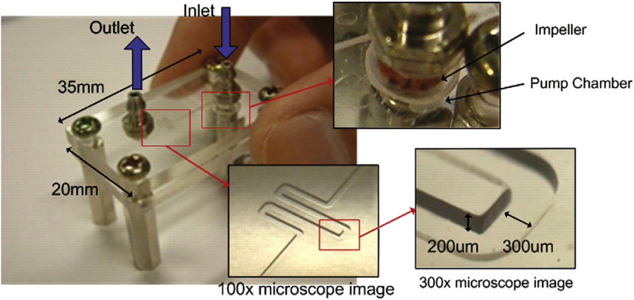
Photo of a vortex micropump with microchannel. The chip size is 20 mm × 35 mm. The diameter of pump chamber is 5 mm. The output microchannel is 300 μm in width, 200 μm in depth.
To characterize the performance of the vortex micropump, experimental and analytically modeled results of its pump rate as a function of rotational speed of impeller is plotted in Figure 3. Basically, the relationship between the pump rate, impeller size, and impeller rotational speed can be related by the following equation:

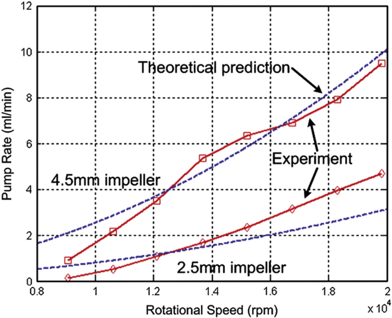
Comparison of the experimental (solid line) and analytical (dotted line) results. The relationship of the pump rate (water as flow medium) and rotational speed of impeller at zero backpressure.
where ρ is the density of the fluid, U is the impeller tip speed, and Pchannel is the flow resistance of connecting microchannel. Typical values for the pump coefficient φ are 0.4–0.7. 9 Basically, the fluid pressure is induced by converting the kinetic energy from rotational motion of the impeller. Then, the pressure decreases because of the flow resistance of the connecting microchannel. Details of the derivation of Eq. (1) and experimental method in obtaining the data in Figure 3 can be found in Ref. 8. In the figure, the pump performance of two different sizes of micro impeller, which are 2.5 and 4.5 mm in diameter, is also compared. In general, due to the operating principle of the vortex micropump, the produced fluid flow rate is proportional to the impeller rotational speed. That is, the pump rate increases with the applied voltage of the DC motor. From the comparison of two different sizes of impeller, the difference in pumping performance is evident. Larger impeller can produce higher fluid flow rate and pressure.
Working Principle
The working principle of micromixing in existing literatures includes generating vortex flow by moving parts in the mixing chamber or going through a three-dimensional structures as described in the pervious section. The fabrication of moving parts and three-dimensional structure is complicated and may not be compatible with other in-plane fluidic components. In this article, a novel micromixing method realized by a simple in-plane mixing mechanism and microfluidic structures is proposed.
The principle of the proposed micromixing is to manipulate fluids as “discretized elements.” The continuous “discretized elements” can increase the interfacial surface area such that the diffusion between fluids can be completed in a shorter time. Because fluidic mixing is enhanced by “discretized fluid,” we refer to this process as “discretized mixing.” Due to the advantage of fast response and controllability of the vortex micropumps, the pumping sequence and flow rate of the micropumps can be programmed by computer software. Two different colored fluids, that is, water and red-dyed water, were used to illustrate the mixing phenomenon in our experiments, which will be presented in Experimental results. Two vortex micropumps were connected to a “Y”-shape microchannel and then an expansion chamber in the downstream, as shown in Figure 4. To eliminate backward flow, micropumps were controlled as either having a high pump rate or a low pump rate to balance the pressure. That is, a micropump is always at minimum flow rate to withstand fluid pressure from the other micropump, as illustrated in Figure 5a. Hence, two vortex micropumps were programmed to pump alternately high and low flow rate, and thereby force fluids coming from two different inlets into a straight microchannel with “chunks” of alternating fluidic mass, called discretized fluids, as illustrated in Figure 5b. Theoretically, diffusion length between two “chunks” of fluids can be decreased by increasing the swapping frequency of micropumps. Moreover, when the discretized fluids are forced into an expansion chamber, their interfacial area increases proportionally and their average axial velocity decreases, which reduces their mixing index, causing the two fluids to mix downstream by diffusion. Furthermore, to enhance the mixing performance, 424 × 424 and 212 × 212 μm2 obstacles were built in the expansion chamber to create complicated flow patterns, as illustrated in Figure 4. In essence, using this working principle, as the swapping frequency of the two micropumps increases, the volume of a single segment of discretized fluid decreases, and the diffusion between two small volumes of fluid can be completed in a shorter time.
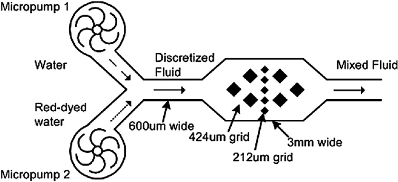
Mixing chamber (3 mm wide) with rectangular obstacles (424 × 424 μm2 and 212 × 212 μm2 grids).
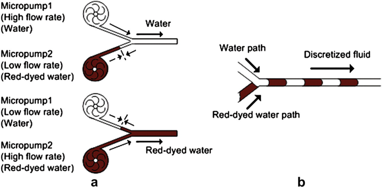
(a) Illustration of pressure balancing mechanism for generating discretized fluid. (b) Illustration of alternating discretized fluids moving along a microchannel.
Numerical Simulation Results
Due to the low Reynolds number, incompressible viscous fluid flowing through a microfluidic channel is laminar. Because of the “layered” flow phenomenon, fluids in microchannels cannot be mixed by themselves, unlike in turbulent flows. In this section, a numerical simulation was performed to understand the fundamental phenomenon of mixing by fluidic descretization. The simulation results were generated by COMSOL Multiphysics v3.4. To demonstrate the mixing phenomenon, fluids in different concentration were assumed and they are represented in light and dark colors in the following figures.
Numerical simulation of discretized fluid flowing through a straight channel is shown in Figure 6. Discretized fluids were assumed to flow from left to right and the flows at the walls were assumed to be in no-slip condition. The Reynolds number is Re = 0.15, which follows our experimental conditions. In the figure, two fluids in different concentrations were injected to a straight channel in discretized volumes. Laminar flow is observed by the parabolic velocity profile, that is, velocity in the centerline flow is larger compared to the region near the two channel walls. The interfacial area between two discretized elements is enlarged due to this phenomenon. Two “tails” of a discretized element become tiny in volume and diffuse into the next discretized element easily. Mixing of the two fluids is observed in the region near the two channel walls but not in the center region. But, as shown, the volume of the center of the discretized fluid is still too large for diffusion in a short time. Increasing the swapping frequency of the discretized fluids is a possible solution for reducing the volume of the discretized elements, but may not be practical as the fluids have a limitation in responding to the vortex pumps. However, injecting discretized fluids to an expansion chamber is a possible solution to increase the interfacial area for diffusion.
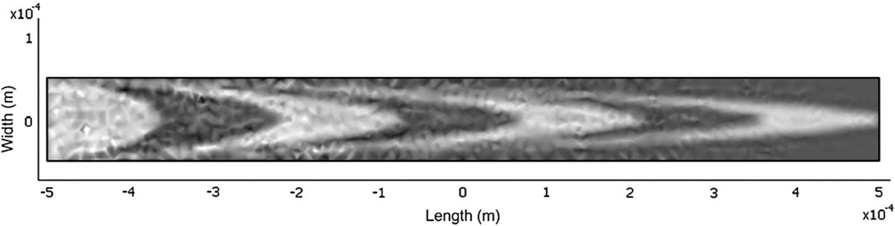
Numerical simulation result of discretized fluid flowing through a straight channel with 100 μm in width and 1000 μm in length. The Reynolds number is Re = 0.15.
The geometry of an expansion chamber used in our experiments and in the simulation is shown in Figure 4. To enhance the mixing performance, obstacles for generating vortices and varying fluid velocity field were built in the expansion chamber. However, we have found that mixing could not be induced when discretized fluids were not generated. A simulation was conducted and the results are shown in Figure 7. Two fluids in different concentration were injected from two inlets and met in the upstream of expansion chamber. The Reynolds number is Re = 30. Velocity field and contour are shown in Figure 7a. Fully developed flows are observed in the upstream and downstream of the expansion chamber. Fluid velocity is slowed down by the expansion chamber and disordered by obstacles. However, the two fluids cannot be mixed by themselves and are still separated after going through the expansion chamber. Although the velocity field becomes complicated in the expansion chamber, the separation of the two fluids is still obvious, as shown in Figure 7b. However, when the discretized fluids are generated and flow through the expansion chamber, simulation results indicate that the fluids could be mixed. As shown in Figure 8, Reynolds number is Re = 30 and the swapping frequency is 20 Hz, two fluids in different concentrations are chopped vertically by the discretized method and horizontally by the obstacles. This complicated flow pattern increases the interfacial area of the fluids and induces mixing downstream of the expansion chamber.
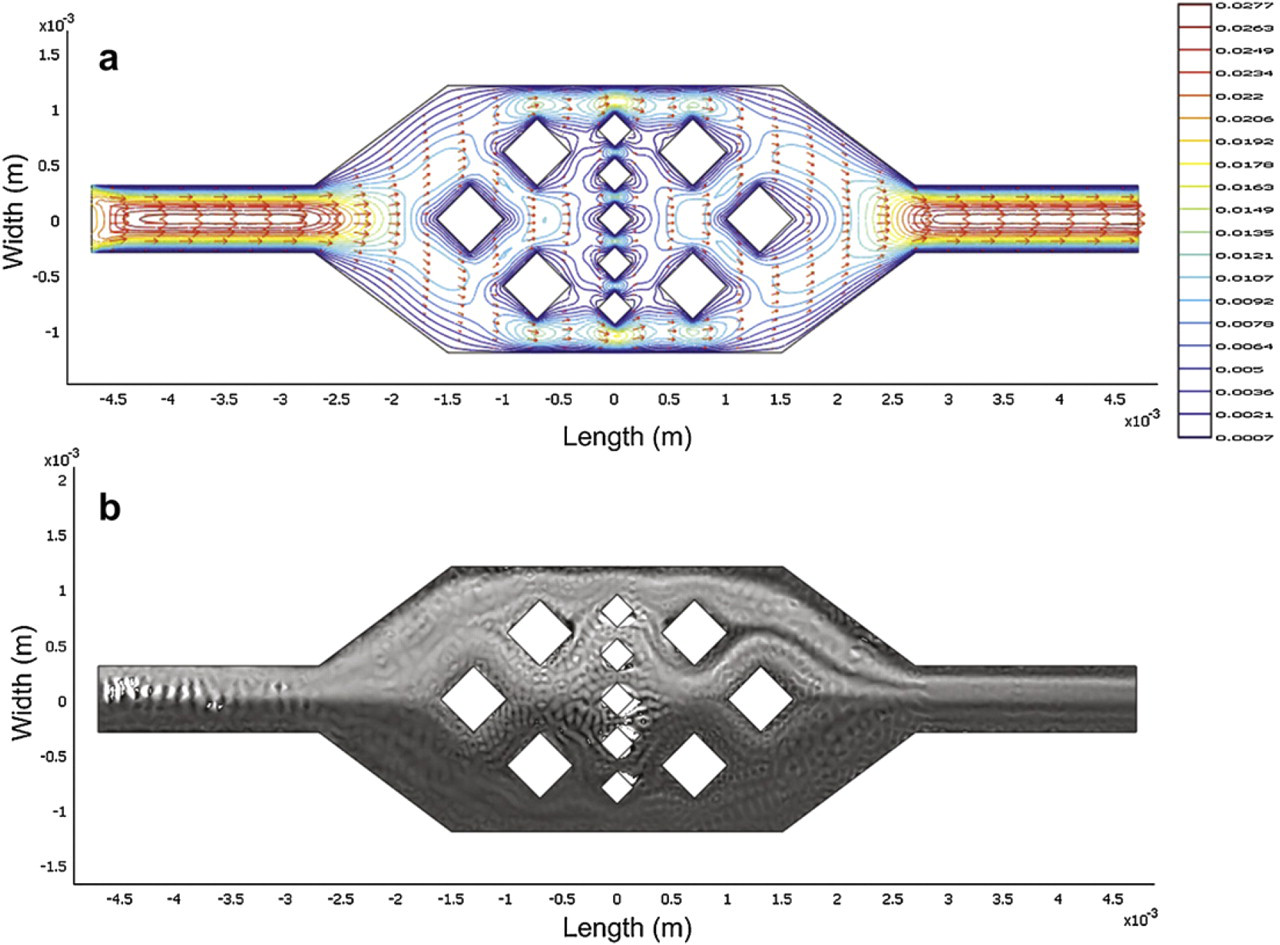
Numerical simulation results of two fluids flowing through an expansion chamber with obstacles, (a) Velocity field and velocity contour, (b) Two separated fluids in different concentrations. The Reynolds number is Re = 30.
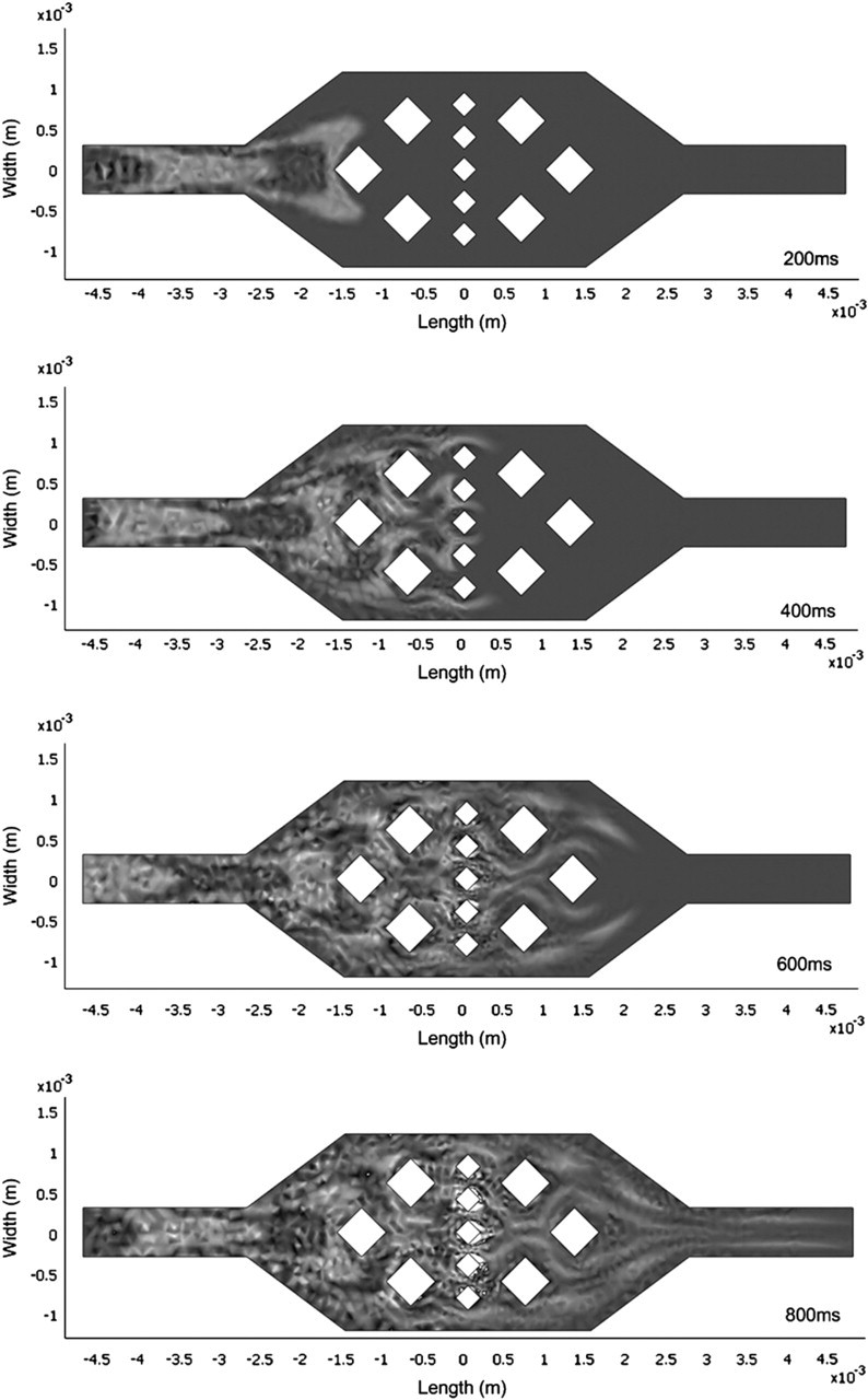
Numerical simulation results of discretized fluids flowing through an expansion chamber with obstacles (in time sequence). The Reynolds number is Re = 30 and the swapping frequency is 20 Hz.
Experimental Results
Fabrication
The micromixer system with vortex pumps described in this article was fabricated by a polymer-based fabrication technique. Details of the related fabrication techniques can be found in Refs. 10–12. Essentially, a PMMA plate with 1.5 mm thickness was used as the substrate. Before the lithography process, the PMMA substrate was cleaned and then placed on a hot plate at 90 °C for 10 min to dry the surface. Then, MicroChem SU-8 2075 negative photoresist was spin-coated onto the PMMA substrate at 2000 rpm for 60 s and a 200-μm thick SU-8 layer was formed. A soft bake was done on a leveled hot plate with slow ramping from room temperature to 65 °C, keeping at 65 °C for 5 min, slow ramping from 65 to 90 °C, and then keeping at 90 °C for 30 min. After the temperature returned slowly to room temperature, the SU-8 layer was exposed under the photomask with the pattern of the expansion chamber and microchannel. A postexpose bake for the cross-linking process was performed using the same parameters as the soft bake. After that, the SU-8 photoresist was developed in a SU-8 developer for about 15 min at room temperature with mild agitation, and then rinsed with ISO-propyl alcohol and deionized water. Finally, UV-cured epoxy resin was spun onto another flat PMMA substrate and bonded to the PMMA substrate with the SU-8 pattern. A microfluidic system integrated with vortex micropumps for generating discretized mixing is hence completed. For the fabrication of vortex micropumps, readers can refer to our prior work in Refs. 7 and 8.
Setup
The discretized mixing phenomenon was demonstrated on an integrated microfluidic system, which has a “Y”-shaped microchannel connected to two vortex micropumps and an expansion chamber, as described in the pervious section. Two different fluids were pumped by two micropumps from two inlets independently and mixed in the expansion chamber. The mixed fluid then left from the outlet of the system. Two inlets of the system were connected to two beakers that served as liquid reservoirs. To demonstrate the mixing performance, one of the beakers was filled with water and another was filled with red-dyed water. The experimental setup is illustrated in Figure 9. The microfluidic system was placed under a microscope for observation and data recording. The pumping sequence was controlled by a computer program.
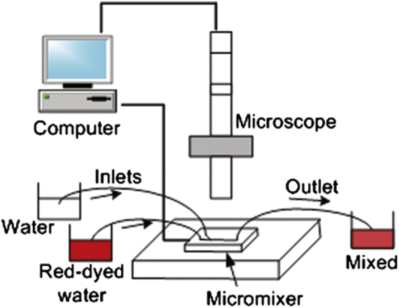
Schematic drawing of the experimental setup.
Results
Mixing did not occurred in the downstream of chamber when water and red-dyed water were pumped at approximately the same flow velocity. As shown in Figure 10, the two fluids left the chamber separately as the diffusion in micro-scale environment was limited. This configuration could not initiate any mixing even though there are vortices and varying velocity field in the chamber. On the other hand, when the two fluids were discretized by vortex micropumps and then expanded in the chamber, a very interesting phenomenon was observed: the fluidic interface length, that is, the mixing performance, is a function of the swapping frequency of the two micropumps. In Figure 11, the discretized fluid at the swapping frequency of 6 Hz was pumped from left to right direction. The time period between two images was 66 ms. It was observed that the fluids were blocked by the rectangular obstacles such that the flow field in the chamber becomes complicated to enhance the mixing performance. The mixing can be observed from the color change of the bulk flow from (a) to (c). In upstream of the chamber, the color of fluid was from red in (a) and (b) to white in (c), that is, two alternating discretized fluids were pumped through the chamber. In downstream of the chamber, the color of the fluid became light red with a bit variation. Consequently, mixed fluid can be generated in the downstream of the chamber.
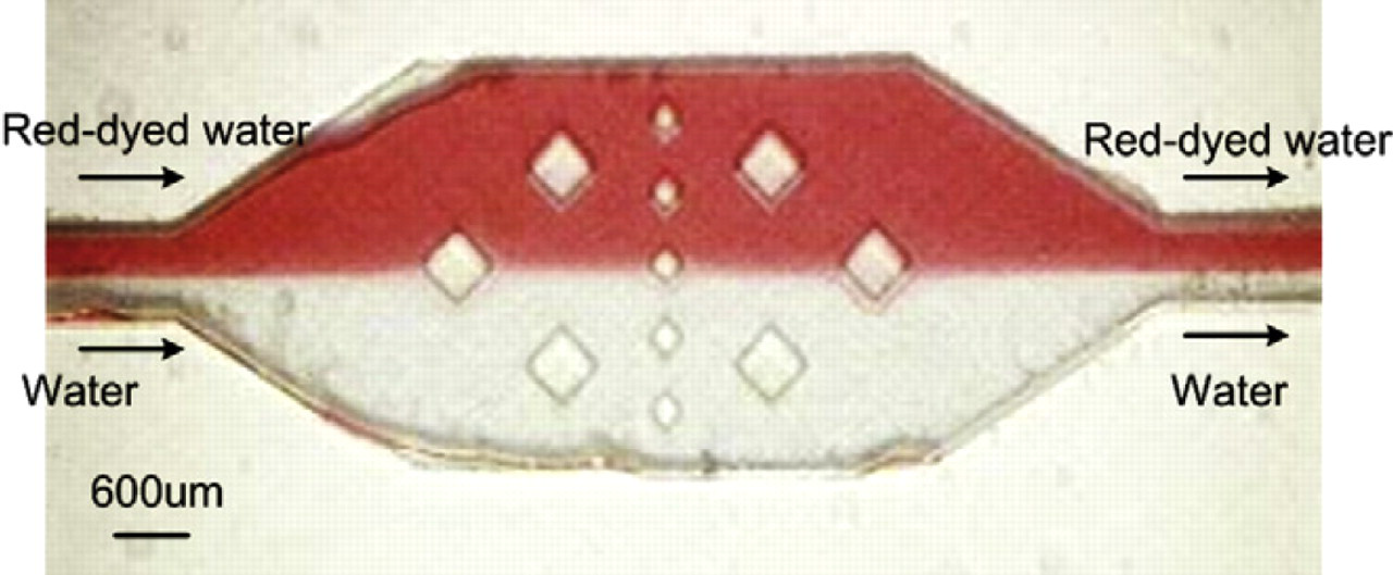
Fluids (D1 water and red ink solution) are pumped into the expansion chamber at approximately the same flow rate. Two fluids flow are clearly distinguishable in the downstream of the chamber, that is, this configuration will not initiate any mixing.
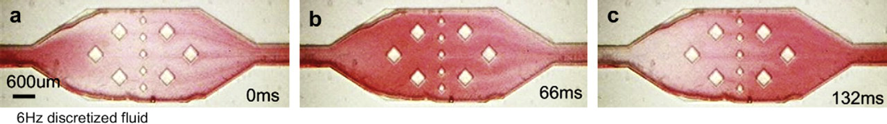
A sequence of microscopic images of one cycle of the discretized fluid, which is discretized by the vortex micropumps at the swapping frequency of 6 Hz. The fluid was pumped into the expansion chamber with obstacles from left to right direction. The time period between two images is 66 ms. Mixing can be observed from the color change of the fluids from (a) to (c). In the upstream of the chamber, the color of fluid was from red in (a) and (b) to white in (c). In downstream of the chamber, the color of fluid kept in light red with a bit variation.
As stated earlier, the mixing performance of the fluids depends on the swapping frequency of the two micropumps. The bulk flow in the downstream of the expansion chamber using different swapping frequencies of the micropumps is shown in Figure 12. The time period between two images is 33 ms and the discretized fluids were pumped from left to right direction. Because discretized fluids for this experiment consisted of water and red-dyed water, the color gradient of the fluid passing through downstream of the expansion chamber reflected the mixing performance. In Figure 12a, with swapping frequency of 3 Hz, a distinguished color gradient was observed from 0 to 99 ms. This means that the mixing of water and red-dyed water was not sufficient at this frequency. When the swapping frequency was increased to 9 Hz, as shown in Figure 12b, the mixing performance was observed to be better, that is, less color gradient is observed compared to 3 Hz. The mixing was observed to be much more thorough with the swapping frequency at 15 Hz, as shown in Figure 12c. As mentioned earlier, theoretically the mixing performance could further be enhanced by further increasing the swapping frequency. However, for our integrated micropump system, we could only generate discretized fluidic elements at a maximum of 15 Hz swapping frequency.
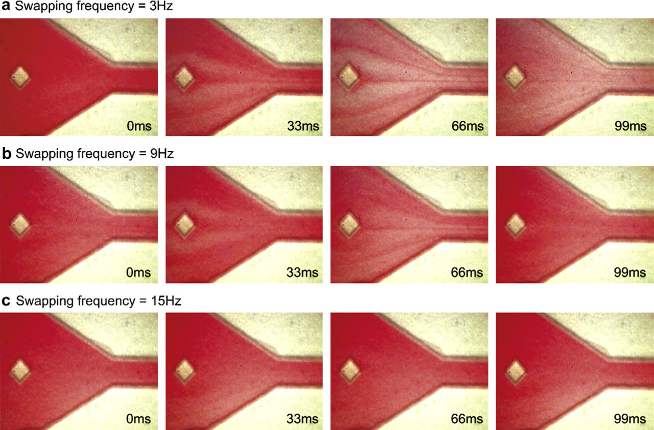
Sequence of microscopic images of discretized mixing at the swapping frequency of (a) 3, (b) 9, and (c) 15 Hz. The time period between two images is 33 ms.
To quantitatively measure the mixing performance of various swapping frequencies, a small control volume (image area of 400 μm × 400 μm) is set at the downstream channel of the expansion chamber to quantify the intensity variation of fluid under a microscope. The digitized color intensity within the control volume was recorded and analyzed while the bulk fluid passed through it. By calculating the average color intensity within the control volume at each frame, the time sequence variation of the intensity reflected the mixing performance. A plot of normalized color intensity at different swapping frequencies of the fluid in the control volume is shown in Figure 13. When the swapping frequency of the discretized fluid was low (i.e., 3 Hz), the color intensity was followed the swapping frequency of the discretized fluid, and the amplitude of color intensity was high. This indicated that the mixing performance was poor because two fluids (water and red-dyed water) passed through the control volume separately. When the swapping frequency of the discretized fluid was high (i.e., 15 Hz), the frequency of the color intensity variation became not clearly defined and the amplitude of the color intensity was low. Also, the intensity amplitude was very close to the ideal mixing performance of 0.5, that is, transparent water has intensity of 0, and red-dyed water has intensity of 1.
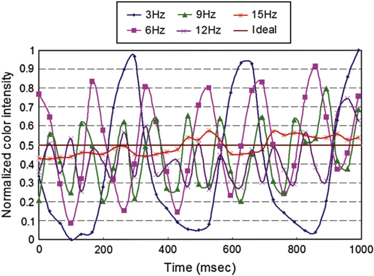
Normalized color intensity of fluid passing through the control volume at different swapping frequencies.
Mixing Index
Microfluidic mixing is dominated by diffusion, which is caused by random molecular motion that leads to complete mixing but which can be a slow process. In general, diffusion in gases progresses at a rate of about 100 mm/min, diffusion in liquids is about 0.5 mm/min, and diffusion in solids may be only about 0.0001 mm/min. 13 -15 If we consider the discretized fluid as an ideal “plug” flow, that is, each segment is assumed to be rectangular shape, then it is possible to approximate the required swapping frequency for mixing given a certain flow conditions. This section presents an analytical approximation to confirm our experimental results. As shown in Figure 14, we assumed the flow in the microfluidic system is generated by two vortex micropumps at a swapping frequency and pumped at a constant volumetric flow rate into a straight microchannel.
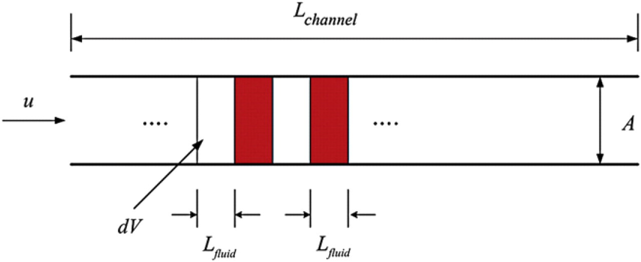
Schematic of discretized pumping, which shows the ideal case of a “plug” flow in a mixing channel of length L channel. As shown, each segment of the discretized fluid has a length of L fluid.
For the discretized mixing discussed in this article, the diffusion length L fluid of alternating segments of fluids (water and red-dyed water) is the maximum length for molecular mixing, which can be determined from

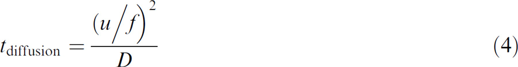
where dV is the volume of each segment of fluid, A is the microchannel cross sectional area, Q is the volume flow rate, f is the swapping frequency of two vortex micropumps, and u is the axial velocity. From Eq. (2), lower velocity or higher frequency results in smaller mixing length, that is, faster mixing. For discretized mixing by molecular diffusion in a segment of fluid with length L fluid, the time required for the diffusion t diffusion is given by:

where D is the diffusion coefficient of the dye by Brownian motion. Because red-dyes are finely suspended solids in water, in general, its diffusion coefficient can be estimated by Stokes-Einstein equation. 13 Fairly accurate values for diffusion coefficients can be found in literature. 16 We assumed the diffusion coefficient for red-dyed water is D = 5 × 10⁻⁷ m2/s. Substituting Eq. (2) in Eq. (3),
On the other hand, the retention time t retention for the discretized fluid in the microchannel with length L channel is determined via:

That is, mixing should have been completed if the diffusion time is less than retention time. The ratio of the two time scales, t* (a dimensionless governing parameter), becomes
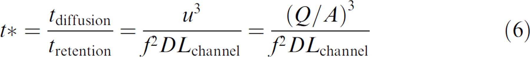
Consequently, the ratio t*, called mixing index, measures whether sufficient time is provided for mixing, that is, if t* ≤ 1, mixing is accomplished, whereas if t* > 1 mixing is not completed. In Eq. (6), note that the axial velocity highly affects the mixing index, that is, lower axial velocity can decrease the mixing index by cube root. Moreover, when swapping frequency increases, the mixing index decreases by square root.
In the previous experiments discussed by Experimental results, discretized fluid entered to a straight microchannel of 600 μm in width with axial velocity u = 0.05 m/s, and Re = 30. The mixing index versus swapping frequency in different microchannel length is plotted in Figure 15. Practically, as shown in the plot, discretized mixing cannot be achieved because at least 10 m long microchannel is required. Therefore, an expansion chamber should be connected after the straight microchannel as discussed in Experimental results. Because the axial velocity is inversely proportional to the width of the microchannel, then, when discretized fluid entered the expansion chamber of 3 mm in width, axial velocity decreased to u = 0.01 m/s. The mixing index versus swapping frequency for different chamber lengths for this velocity is plotted in Figure 16, which shows that the mixing index falls under 1 for all chamber lengths. In the experiment, the chamber length was around 10 mm. Figure 16 indicates that theoretically discretized mixing could occur when the swapping frequency is 15 Hz, which confirms the experimental observations.
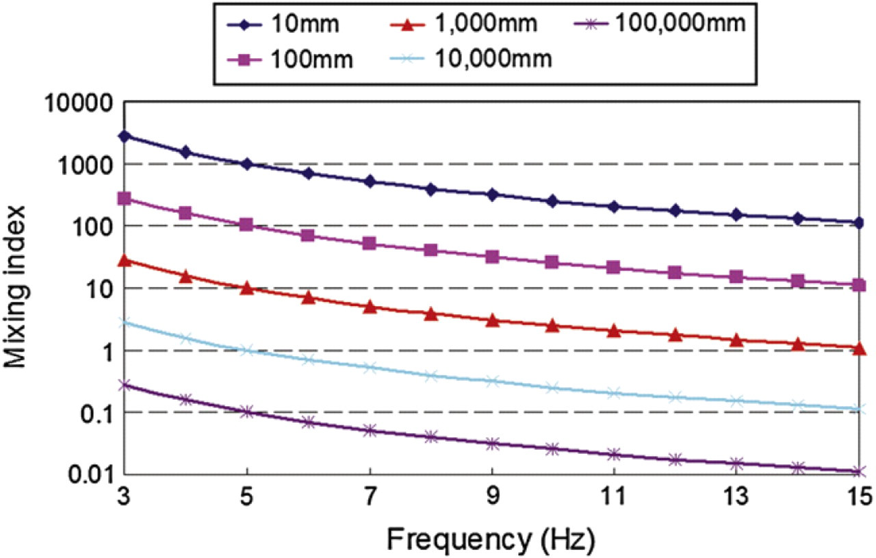
Discretized mixing index versus swapping frequency of two vortex micropumps in different microchannel lengths. Axial velocity of discretized fluid is u = 0.05 m/s.
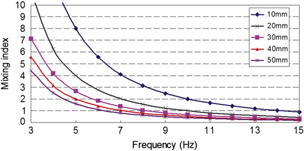
Discretized mixing index versus swapping frequency of two vortex micropumps in different chamber length. Axial velocity of discretized fluid is u = 0.01 m/s.
Conclusion
In this article, a novel in-plane micromixer using fluidic discretization has been reported. The design, fabrication, simulation, and experimental results of this mixing system have been described. The mixing phenomenon was demonstrated in an integrated microfluidic system consisting of two vortex micropumps, an expansion chamber, and two connecting microchannels. Numerical simulation has elaborated the flow field in the chamber and shows discretized mixing in detail. We have proved that the mixing chamber does not require any additional external power to induce mixing. The mixing performance shown in the experimental results is comparable to an ideal mixing phenomenon and shows reasonably good match with the simulation results. Consequently, a dimensionless governing parameter, mixing index, of the discretized mixing was developed to estimate the mixing performance. This derived mixing index would be helpful in the design of future discretized mixing systems. Because this discretized mixing requires simple in-plane mechanism and microfluidic structure, it could be easily integrated with other fluidic components. Furthermore, PMMA was chosen for the structural material of the system, which is optically transparent and biocompatible, and hence the system discussed in this article is suitable for biochemical applications.
Acknowledgment
We thank Prof. Wallace Leung of the Hong Kong Polytechnic University for fruitful and in-depth discussion on the diffusion phenomenon. The authors would alos like to thank the Hong Kong Research Grants Coucil for Supporting this Project (Project No. CUHK4177/04E).