
Abstract
3D-printed laboratory devices can enable ambitious research purposes even at a low-budget level. To follow this trend, here we describe the construction, calibration, and usage of the FINDUS (Fully Integrable Noncommercial Dispensing Utility System). We report the successful 3D printing and assembly of a liquid-handling workstation for less than $400. Using this setup, we achieve reliable and flexible liquid-dispensing automation with relative pipetting errors of less than 0.3%. We show our system is well suited for several showcase applications from both the biology and chemistry fields. In support of the open-source spirit, we make all 3D models, assembly instructions, and source code available for free download, rebuild, and modification.
Introduction
The open-source movement, originating from Do-It-Yourself-scene software engineers during the late 1960s, has outlasted the decade but also changed paradigms with the availability of cost-efficient 3D printers.1,2 About 10 years ago, 3D printers were still unaffordable for end consumers, but the costs have decreased dramatically since about 2013, due to the expiration of crucial fused deposition modeling (FDM) patents.3–6
Most 3D printer users share their ready-to-print assembly instructions in online repositories such as MakerBot Thingiverse 7 or the National Institutes of Health’s 3D-print exchange. 8 Consequently, users with access to a 3D printer can freely reprint and modify the relevant model.
3D printers operate by melting a filament of plastic, such as polyethylene terephthalate glycol-modified (PETG), at the heated nozzle to build a 3D object in layers. 9 By now, most midrange 3D printers cost a few hundred dollars, with marginal operating expenses of about $30/kg printed material. 10
It comes as no surprise that scientists from diverse fields use these technologies to build or customize laboratory equipment. Recently reported devices include constructions ranging from optics equipment 11 to biomolecular models, 12 handheld pipets, 13 synthesis reaction-ware, 14 nutating mixers, 15 continuous-flow reactors, 16 and other inventions summarized in several reviews.17–20
A nearly unlimited spectrum of possibilities emerges when 3D-printed mechanical parts are combined with microcontroller electronics. Recently, scientists developed several laboratory equipment instruments with low-budget open-source microcontrollers like Arduino 21 and Raspberry Pi, 22 yielding highly specialized laboratory equipment such as arthropod venom extractors, 23 microfluidic flow cytometers, 24 solid-phase peptide synthesizers, 25 environmental data collection systems, 26 RNA/DNA extractors, 27 and radiochemistry synthesis devices. 28
Handling of liquids plays a central role in most experiments for the life sciences. The volumes are usually in the low-microliter range, and the number of transferred samples can be large when a combinatorial design of experiment is used. Therefore, manual liquid handling is often impractical, tedious, and prone to human error.29,30 Consequently, there is a need for automated liquid-handling methods with higher accuracy and consistency. Commercially available liquid-handling workstations fulfill these needs but are often unaffordable (>$30,000) for academic research institutions. 31 Furthermore, most commercial devices use a proprietary system architecture unsuitable for adaptive changes in the hard- or software components, although such changes are often needed for innovative research projects.
Open-source-based approaches to liquid handling were widely unknown before 2016, but recent advances led to a significant change in the landscape, with many producers introducing cheaper and more interoperable devices. The Andrew robot 32 can pick up conventional pipets from built-in racks using a camera to guide the movement of the robotic arm. Liquid-handling robots from Opentron are almost one order of magnitude cheaper than previous devices ($4000) 33 and contain an XYZ-gantry system that can handle standard pipets by mechanical control. Opentron’s open-source concept recently led to innovative applications (e.g., devices for the production of human cell spheroids 34 or malaria parasite culturing 35 ). Another invention, the OpenLH robot, integrates a commercially available robotic arm with custom 3D-printed parts and was set up for less than $1000. 36 Gerber et al. constructed a liquid-handling device around the LEGO Education EV3 core set. 37 While being primarily designed for education, this device shows also potential for research applications.
To contribute to this highly active research field, we report the design, 3D printing, and proof of an easy-to-rebuild liquid-handling robot for less than $400 in material costs, less than 50 hours of construction work, and an additional 50 hours of 3D-printing time.
Materials and Methods
Materials for Construction
We purchased precision shafts, linear bearings, tooth belts, belt pulleys, and joints from Motedis (Ensdorf, Germany).
3D Printing
We fabricated the 3D-printed parts with an Anycubic 4Max printer (Shenzhen, China). By means of the open-source software FreeCAD 38 (LPGLv2+) and Ultimaker Cura 15.04.6 39 (LPGLv3), we designed, meshed, and sliced individual components. For the design of gears, we used the FreeCAD workbench “gear.” We performed printing through a 0.4 mm nozzle with 1.75 mm ± 0.02 mm PETG filament (3D Hero, purchased on amazon.de) at 225 °C. The layer thickness was 0.2 mm. By soaking the printed parts, we reinforced mechanically stressed parts like the gear housing, X-slide, and Z-support with SR555 epoxy resin (Sicomin, Chateauneuf Les Martigues, France). 3D models (FCstd- and stl-files) can be downloaded for modification and reprinting from https://github.com/FBarthels/FINDUS.
Electronics
We chose an ESP8266 12F microcontroller from Espressif Systems (Shanghai, China) to control the movable parts of the FINDUS and programmed the microcontroller with Arduino IDE (integrated development environment) 1.8.8 [General Public License (GPL)]. OMC Corporation Ltd. (Nanjing City, China) was the commercial source for all NEMA (National Electrical Manufacturers Association) stepper motors used in this work. For the XY drives, we used bipolar NEMA 17 stepper motors (2 A, 1.8 °/step, 59 Ncm); for the Z drive, a bipolar NEMA 17 (26 Ncm); and for the pipet drive, a NEMA 11 (6 Ncm). Step-down boards provided a voltage of 3.3 V for the ESP8266 12F. DRV8825 controller boards from Pololu Electronics (Las Vegas, NV) controlled stepper motors using a motor library provided by Laurentiu Badea under MIT license.
40
Parameters used for this library were microstepping=32, speed profile=LINEAR_SPEED, Accel-Param=1000, and Decel-Param=1000. The ESP8266 was in access point mode. We set up a 10.0.0.0 private WiFi network for communication with the control computer.
Software
After completion of the FINDUS board, we programmed it via the Arduino development interface and flashed it using a serial FTDI (Future Technology Devices International) adaptor from AZDelivery (Deggendorf, Germany). Only the primary flashing required the serial adaptor. We performed further program updates via WiFi using the HTTPUpdateServer library available in the Arduino environment.
We installed an information library and standard library for the ESP8266 microcontroller via the PC board manager. Among the available board settings, we selected the following NodeMCU 1.0 ESP-12E Module settings: FlashSize, 4M (1M SPIFFS); DebugPort, disabled; DebugLevel, none; CPU Frequency, 80 MHz; and UploadSpeed, 115000.
Based on Python (GPL-compatible license), we developed a FINDUS module in an object-oriented programming style, which contained all functions to control the robot. For the communication with the microcontroller, we used the Python library requests (Apache2 license) and the Python library dill (3-clause BSD license) to store instantiated classes. The complete source code can be obtained from https://github.com/FBarthels/FINDUS.
Configuring the Motorized Piston Stroke and Calibration
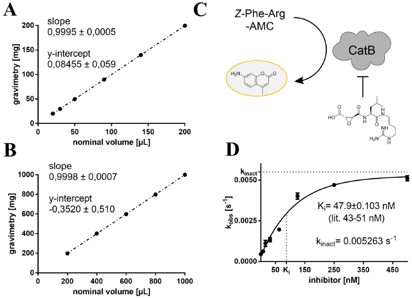
We accomplished a gravimetric calibration procedure as prescribed in DIN EN ISO 8655 to configure the motorized piston stroke and to assay the accuracy and precision of the liquid-handling workstation. 41 The model pipet Pipetman P200 and P1000 from Gilson (Middleton, WI) contained a displacement piston (4 mm diameter for the 200 µL pipet and 8 mm for the 1000 µL pipet) made of ground and polished hardened steel, which was moved directly by a computer-controlled, stepper motor–driven lifting axle. We determined the volume of deionized water dispensed by density-corrected 42 weightings in 1.5 mL polypropylene Eppendorf tubes (CarlRoth, Karlsruhe, Germany). In terms of gravimetric methods, we exploited the conventional guidelines for the use of a semi-microbalance. On a Quintix35-1S (Sartorius, Göttingen, Germany) analytical balance, we performed gravimetric analysis with 10 technical replicates for each data point and repetition thrice on 3 nonconsecutive days. We developed a calibration program as shown in the supplemental materials.
Inhibition of Cathepsin B by the E-64 Inhibitor
We investigated the inhibition of human cathepsin B (Calbiochem, Merck Millipore, Burlington, MA) by the epoxide inhibitor E-64 (AppliChem, Darmstadt, Germany) by means of a fluorometric enzyme assay as reported previously. 43 We prepared a stock solution of the cathepsin B protease (final concentration: 2 pM) in assay buffer (20 mM Tris-HCl, pH 6.0, containing 5 mM EDTA, 2.5 mM DTT, 200 mM NaCl, and 0.005% Brij 35). An Infinite F200 Pro (Tecan, Männedorf, Switzerland) multiplate reader monitored the increase of fluorescence on cleavage of the fluorogenic substrate Cbz–Phe–Arg–AMC (Bachem, Bubendorf, Switzerland). We performed all pipetting steps to set up the assay using the automation script as shown in the supplemental materials. Stock solutions of the substrate (final concentration: 100 µM) and E-64 were prepared in DMSO. We carried out three technical replicates in a volume of 90 µL in black flat-bottomed 96-well microtiter half-area plates (Greiner Bio-One, Kremsmünster, Austria) and negative inhibition control by mock treatment with pure DMSO. Fitting of the kobs values against the inhibitor concentrations to the hyperbolic equation kobs = kinac[I] / (KIapp + [I]) gave the individual values of KIapp and kinac. We corrected the KIapp values to the substrate concentration by the Cheng–Prusoff equation KI = KIapp / (1 + [S] / KM). 44
Solid-Phase Peptide Synthesis
An ESP8266 from Espressif Systems controlled the solid-phase synthesis module by connecting the WiFi station to the microcontroller of the FINDUS base system (access point). For the shaker, we used a NEMA 17 stepper motor (59 Ncm), and for vacuum aspiration a 12 V vacuum pump (120/−65 KPa, 5 L/min), from Aiyima (Shanghai, China).
We synthesized peptides by Fmoc-based solid-phase peptide chemistry using the homemade peptide synthesis module of the workstation and the script shown in the supplemental materials. Sigma-Aldrich (St. Louis, MO) supplied the chemicals used for the peptide synthesis. We performed the synthesis on Novabiochem (Merck Millipore) Wang resin (1.1 mmol/g) and a standard TBTU coupling protocol 45 by coupling each amino acid in threefold molar excess for 60 min with 2-(1H-benzotriazole-1-yl)-1,1,3,3-tetramethyluronium-hexafluorophosphate (TBTU) and N-methylmorpholine (NMM). We removed the Fmoc group twice with 40% piperidine in dimethylformamide (DMF) for 10 min and 20 min, respectively, and finally cleaved the peptide from the resin with trifluoroacetic acid (TFA)/triisopropylsilane/water (90/5/5) for 3 h. Precipitation with −80 °C cold ether, centrifugation, and lyophilization from water/acetonitrile (1:1) yielded the crude peptides. We determined success and purity by combined high-performance liquid chromatography (HPLC)/electrospray ionization mass spectrometry (ESI-MS) analysis using an Agilent (Santa Clara, CA) 1100 series HPLC system with an Agilent Poroshell 120 EC-C18 column (150×2.10 mm 4 µm column; mobile phase: ACN/H2O 45:55 + 0.1% formic acid; flow rate: 0.4 mL/min). The HPLC detection wavelength was 254 nm. We used the Agilent 1100 series LC/MSD (Liquid Chromatography/Mass Selective Detector) trap in positive ionization mode.
Results and Discussion
Designing the Pipetting Arm
We designed the FINDUS primarily to automatize repetitive liquid-handling tasks in a modern life science laboratory. The basis for the liquid transfer machinery was a commercially available micropipet integrated with a displacement piston (
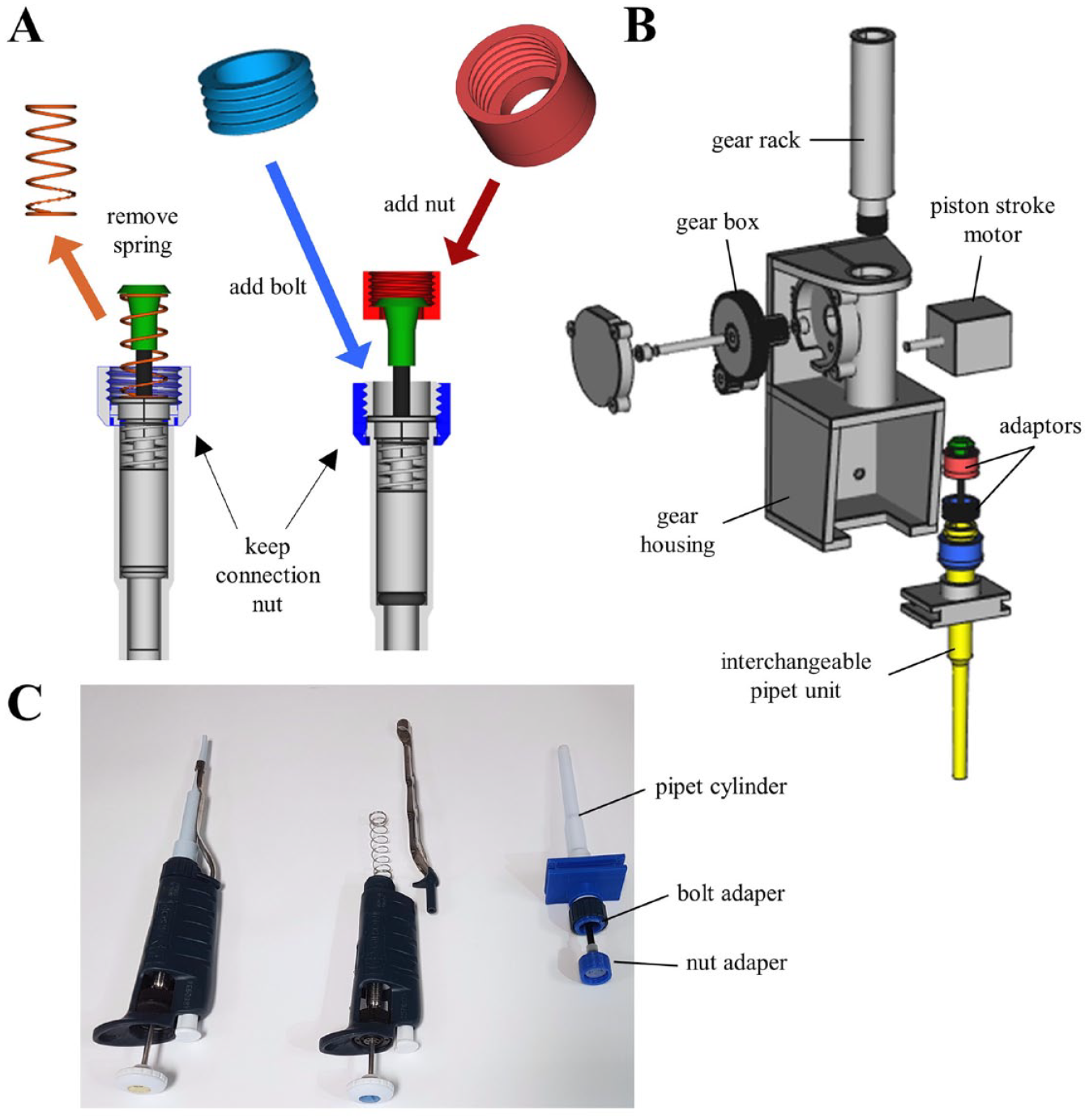
Construction of the FINDUS (Fully Integrable Noncommercial Dispensing Utility System) pipet arm and housing. (
Setting Up a Working Area
We chose the size of the available working area of the robot to be 300×420 mm, allowing the placement of several experimental setups at the same time (
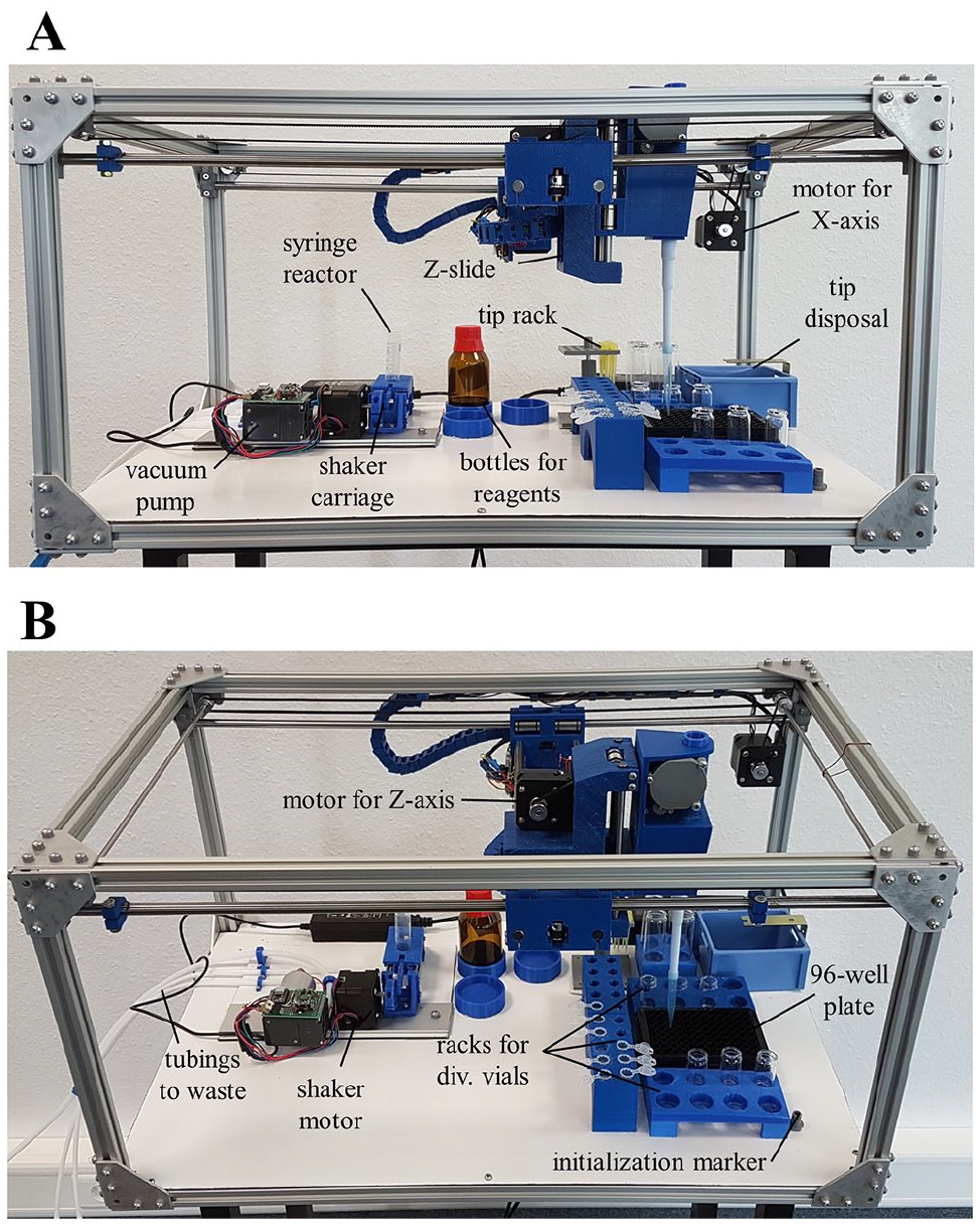
The FINDUS (Fully Integrable Noncommercial Dispensing Utility System) working area with sample models of 3D-printed racks used in our setup. (
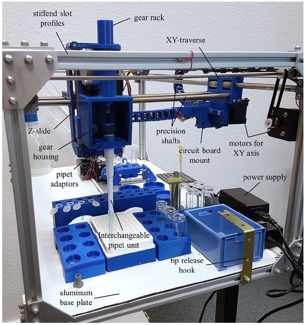
The FINDUS (Fully Integrable Noncommercial Dispensing Utility System) from the side view. The interchangeable pipet unit is mounted to the gear housing with a gear rack. The Z-slide and XY-traverse are moved on precision shafts and linear bearings by three stepper motors (XYZ).
An essential characteristic of the FINDUS was the flexibility in (re)placing the bins on the base plate. We designed different racks for liquid vessels, so-called Bins, printed in PETG. To fix the racks, we used double-sided adhesive tape because it allows rearrangement without great effort. Since the relative distances within the rack were not changed, only the new rack position had to be acquired in a new arrangement. We designed racks for 1.5 and 2.0 mL Eppendorf tubes, 6–25 mL glass vials, 100 mL bottles, 96-well plates, and spring-loaded racks for pipet tips (200 and 1000 µL) to allow automatic tip changing and release (
ESP8266 Implementation
Among hundreds of available microcontrollers, the ESP8266 offered at least two advantages compared to most competitors in the price range of less than $10: (1) It was easy to implement the Arduino development environment;
46
and (2) the ESP8266 can run in access point mode, allowing the installation of additional ESP8266-driven modules without changing the network structure or the existing source code.
47
The software implemented on the ESP8266 controlled only the basic features of the stepper motors. We implemented the actual workstation in a Python environment on a remote-controlling personal computer (PC) or smartphone (
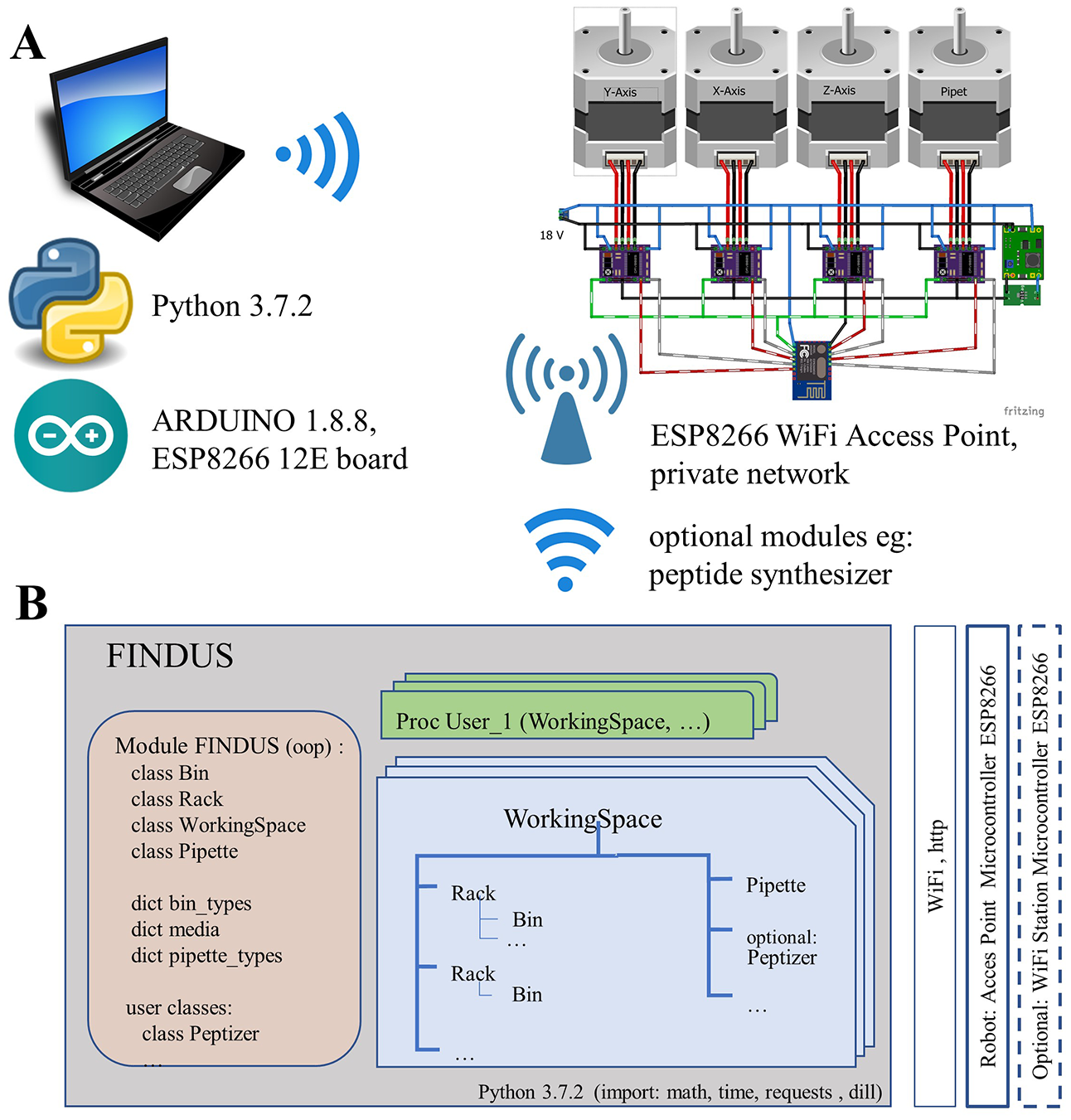
Soft- and hardware architecture to manage and control the FINDUS (Fully Integrable Noncommercial Dispensing Utility System). (
The ESP8266 operated as an access point with a private 10.0.0.0 network using the WPA+WPA2 standard and managed up to 10 clients simultaneously. Communication took place via a web server to which the PC sent commands via HTTP-Post requests. We implemented the following requests: INIT, RESET, SET_POS, MOVE_XY, MOVE_X, MOVE_Y, MOVE_Z, and MOVE_PIP. The MOVE requests required a parameter speed [revolutions per minute (rpm)] to control the speed of the robot over a wide range.
For stepper motor control, we integrated a library, 40 which made speed ramping of the steppers available. The stepper motors for the XY coordinates operated as multidrivers so that both motors started simultaneously, and whichever reached the endpoint first stopped while the other continued to run. We maintained the absolute position of the stepper motors (number of steps after initialization) over requests and returned as a reply with each request. This ensured that after initialization of the zero point, the stepper motors do not attempt to move robot parts beyond the physical limits.
FINDUS Python Script
We developed a Python-based FINDUS module and made it available for download, adaptation, and extension to the user’s choice from GitHub (
Methods in the Pipette class controlled the pipet action. The pipet was instantiated using a dictionary with pipet types, URL of the robot, and so on. Instantiated racks and pipets defined a WorkingSpace. The WorkingSpace class implemented the actual methods for a logical pipetting order or tip changing. Additional modules (e.g., a peptide synthesizer) can optionally be integrated into a WorkingSpace. A sequence of calls of WorkingSpace methods fulfilled the actual pipetting task. We implemented liquid transfers between source and target, or more complex tasks like dilution series, on this level. In addition, the pipetting step can be specified in more detail with further parameters such as speed, humidification, or multidispensing from the pipet.
To group this sequence, there was a truncated class (“UserProc”), which implemented standard methods. The methods “init()” and “run()” were defined by the user. These instantiated user classes can be saved and reloaded. For verification of the program flow, we included a simulation mode in offline setup.
Setting Up the Motorized Pipet Arm
We configured the motorized piston stroke by fitting the stepper motor’s rotation to the gravimetrically determined pipetting volume at five different nominal volumes. For the 200 µL pipet, nominal volumes were 20, 50, 90, 140, and 200 µL. The 1000 µL pipet nominal volumes were 200, 400, 600, 800, and 1000 µL. We assumed for both pipets a linear relation between the piston stroke and the dispensed volume. Thus, we started the calibration in the middle of the working range at 90 µL and 600 µL, respectively, with an estimated calibration value based on the displaced volume of the piston diameter of the pipet (4 mm and 8 mm).
We performed an iterative calibration procedure by linear interpolation from the nominal volume and the averaged measured masses. By this, we determined a refined calibration value for each pipet. With this refined calibration value, we carried out a new series of measurements. After three iterations, the calibration value was stable for both pipets. With the iterated calibration value for 90 µL and 600 µL, respectively, we performed measurement series for all nominal volumes and fitted these using linear regression (see script in the supplemental materials).
Calibration of the FINDUS Performance
Devices for liquid handling should be calibrated to ensure their performance with accepted standards, such as DIN12560 or ISO8655. 41 Skilled experimenters are usually capable of limiting the permissible random error to 1–2%. 29 Semac et al. and Lochner et al. probed and summarized frequent error sources in the life science laboratory and their contribution: uneven rhythm (1.5%), incorrect tip immersion depth (1%), and deviation from verticality (1%).48,49 By separating the conventional handle and button part of a pipet, we controlled the piston stroke by means of a stepper motor. The stepper motor allowed a positional accuracy of the piston stroke of approximately 2 µm. With our setup, we could avoid all significant sources of errors for manual pipetting precision.
We tested the accuracy of the pipetting performance after calibration at all nominal volumes for both pipets. Thus, we performed five independent replicates to determine the maximum relative error for each pipet given from the gravimetric analysis (
Determination of the Pipetting Performance by Means of the Gravimetric Protocol, as Described in ISO8655.
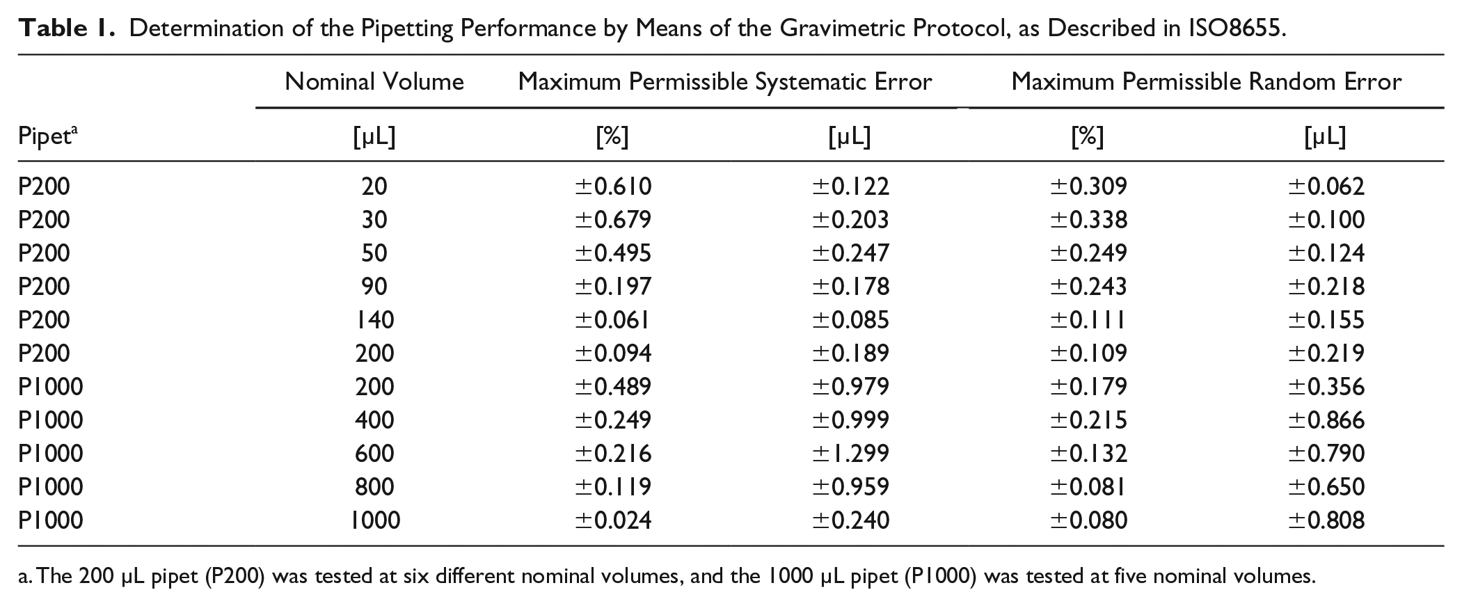
The 200 µL pipet (P200) was tested at six different nominal volumes, and the 1000 µL pipet (P1000) was tested at five nominal volumes.
Pre-wetting of the pipet tip by a single dispensing of the nominal volume led to a significant improvement in the reliability and was integrated into all pipetting steps in the enzyme assay. If pre-wetting was omitted, Joyce et al. found the first values of a measurement series were significantly smaller because of insufficient water vapor saturation in the tip. 50
We identified two further factors as critical parameters for reproducible pipetting results: the piston stroke speed and the immersion depth of the pipet. We limited the piston stroke speed to 4 mm/s to allow the quasi-stationary uptake of the liquid into the tip without a latent negative pressure in the dead volume of the pipet. We chose the immersion depth (3 mm) below the liquid surface to be as small as possible without risking the absorption of air bubbles. The current filling level was simultaneously calculated from the quantity of liquid removed or added.
Our system design goals were accuracy performance and accessibility rather than speed. We benchmarked the FINDUS operating speed at a piston stroke speed of 4 mm/s. With a single-channel pipet, we filled a 96-well plate in 03:30 min. By using eight-channel pipets, the fill time can be drastically reduced to approximately 25 s per 96-well plate. We also set up a standard biological assay (24 wells total) with multidispensing variable volumes in about 01:00 min. We performed a video presentation illustrating the pipetting performance for the 24-well assay (www.github.com/FBarthels/FINDUS/tree/master/videos).
Solid-Phase Peptide Synthesis
We designed the peptide synthesis module to synthesize small to medium-sized peptides (4–20 amino acids) on a small scale (<0.5 mmol). We selected 2×10 mL disposable syringes as the reactive receptacle to carry out two parallel synthesis batches and introduced a polypropylene frit into each syringe (
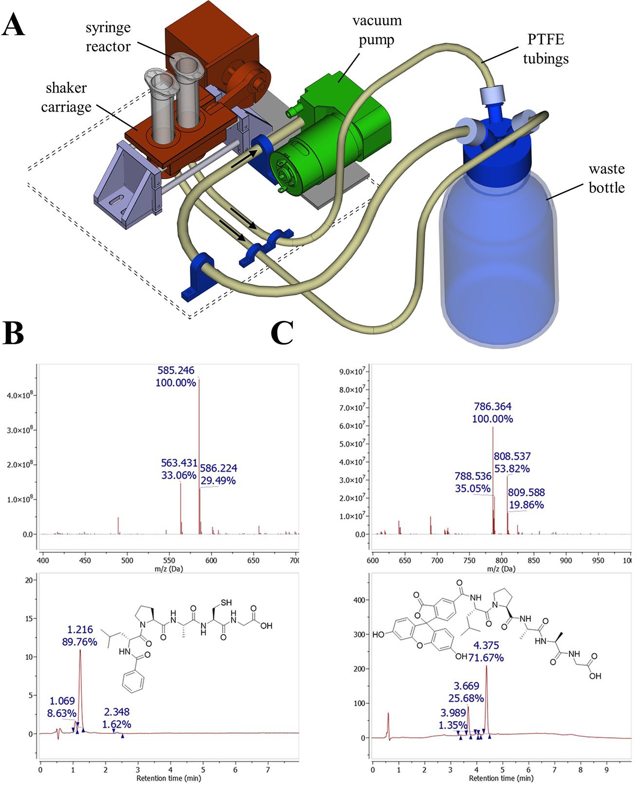
Peptide synthesis module. (
Cathepsin B Assay
Lysosomal cathepsin B is strongly inhibited by the naturally occurring epoxide E-64 extracted from Aspergillus japonicus.
51
The epoxide reacts with an active-site thiol group of cysteine proteases to form a thioether. Inhibition of cathepsin B by E-64 was previously assayed with a fluorometric Z-Phe-Arg-AMC assay (
Calibration of the FINDUS (Fully Integrable Noncommercial Dispensing Utility System) and pipetting performance during an enzyme assay. (
Supplemental Material
sj-pdf-1-jla-10.1177_2472630319877374 – Supplemental material for FINDUS: An Open-Source 3D Printable Liquid-Handling Workstation for Laboratory Automation in Life Sciences
Supplemental material, sj-pdf-1-jla-10.1177_2472630319877374 for FINDUS: An Open-Source 3D Printable Liquid-Handling Workstation for Laboratory Automation in Life Sciences by Fabian Barthels, Ulrich Barthels, Marvin Schwickert and Tanja Schirmeister in SLAS Technology
Footnotes
Supplemental material is available online with this article.
Declaration of Conflicting Interests
The authors declared no potential conflicts of interest with respect to the research, authorship, and/or publication of this article.
Funding
The authors disclosed receipt of the following financial support for the research, authorship, and/or publication of this article: Johannes Gutenberg University of Mainz.
References
Supplementary Material
Please find the following supplemental material available below.
For Open Access articles published under a Creative Commons License, all supplemental material carries the same license as the article it is associated with.
For non-Open Access articles published, all supplemental material carries a non-exclusive license, and permission requests for re-use of supplemental material or any part of supplemental material shall be sent directly to the copyright owner as specified in the copyright notice associated with the article.