
Abstract
The application of 3D printing and microcontrollers allows users to rapidly engineer novel hardware solutions useful in a laboratory environment. 3D printing is transformative as it enables the rapid fabrication of adapters, housings, jigs, and small structural elements. Microcontrollers allow for the creation of simple, inexpensive machines that receive input from one or more sensors to trigger a mechanical or electrical output. Bringing these technologies together, we have developed custom solutions that improve capabilities and reduce costs, errors, and human intervention. In this article, we describe three devices: JetLid, TipWaster, and Remote Monitoring Device (REMIND). JetLid employs a microcontroller and presence sensor to trigger a high-speed fan that reliably de-lids microtiter plates on a high-throughput screening system. TipWaster uses a presence sensor to activate an active tip waste chute when tips are ejected from a pipetting head. REMIND is a wireless, networked lab monitoring device. In its current implementation, it monitors the liquid level of waste collection vessels or bulk liquid reagent containers. The modularity of this device makes adaptation to other sensors (temperature, humidity, light/darkness, movement, etc.) relatively simple. These three devices illustrate how 3D printing and microcontrollers have enabled the process of rapidly turning ideas into useful devices.
Introduction
To address the needs of our drug discovery research labs, we have applied computer-aided design (CAD), 3D printing, and microcontrollers to expand the functionality of existing equipment and build new, custom devices. Articles in the PubMed database containing the term “3D printing” have been steadily increasing since 2005, with the first article on 3D printing published in 1996 ( Fig. 1A ).1,2 Likewise, papers using the term “microcontroller” go back to 1981, but the number of articles has only started growing steadily since the early 2000s ( Fig. 1B ). 2 The popularity of the Arduino microcontroller platform is evident by the growth in Arduino references in the last 5 years ( Fig. 1C ). 2 The rapid adoption and use of these technologies reflects their transformative potential in a lab setting. 3 Somewhat surprisingly, in 2017 there were relatively few papers referencing both 3D printing and microcontrollers (or Arduinos), suggesting that these technologies are still not frequently implemented together ( Fig. 1D ). 2 In our experience, bringing 3D printing and microcontrollers together enables rapid development, prototyping, and implementation of custom-engineered devices.
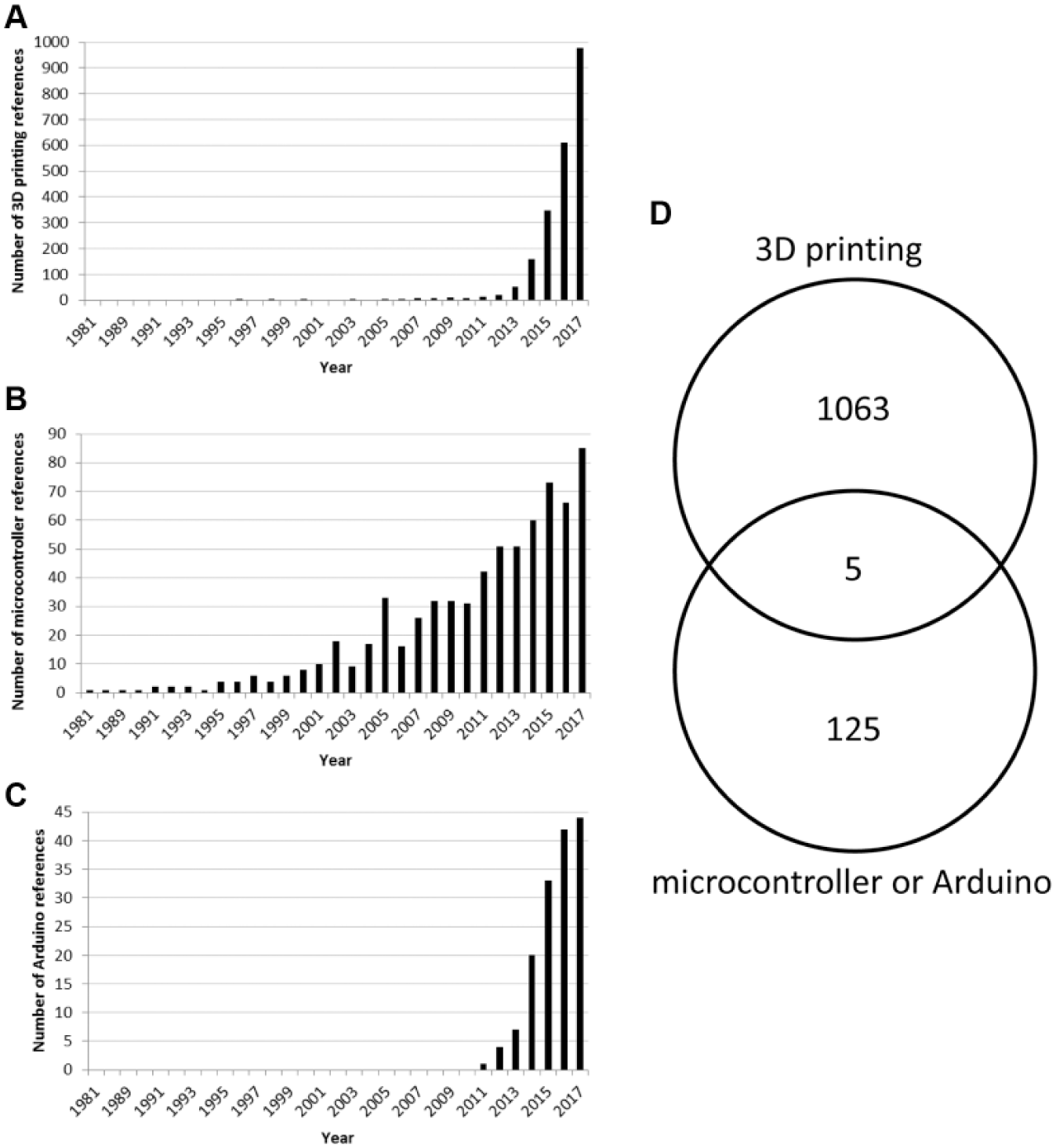
Results from PubMed database queries show an increasing number of references to 3D printing, microcontrollers, and Arduinos. Papers were included that contained the terms “3D printing” (
3D printing refers to the process of making a three-dimensional object through additive manufacturing. Additive manufacturing is the process of building an object by adding layers of material on top of each other. This can be achieved through the melting of plastic that is extruded into a thin molten filament applied in a specific pattern, commonly known as fused deposition modeling (FDM) or fused filament fabrication (FFF). The object is formed as layers are applied on top of previous layers that have cooled and solidified. Other techniques use photoactivated liquid resins that polymerize following intense light exposure. The resin can be dispensed in specific patterns using inkjet technology (stereolithography), or objects can be formed as high-resolution images are projected into a pool of resin to form layers (mask image projection–based stereolithography). A variety of plastics are currently available, with each possessing its own characteristics for strength, flexibility, shrinkage, chemical and heat resistance, quality of finish, and cost. Not only does 3D printing enable the creation of relatively inexpensive objects, but also the speed of fabrication is transformative. When designing new objects, we find that the iteration cycle is on the order of hours instead of the days or weeks required for other manufacturing processes.
Microcontrollers function essentially like small, simple computers and are made up of a processor, memory and input/output pins. Among the most popular microcontrollers are the open-source Arduino microcontrollers. The Arduino platform uses an integrated development environment (IDE) compatible with Windows, Mac, and Linux operating systems that allows users to write firmware that monitors inputs and performs logic based on those inputs. The hardware is relatively inexpensive (approximately $25), and simple input/output devices are readily available. When the firmware is uploaded to the Arduino, the processor uses those instructions to trigger outputs based on specific inputs. These can be as simple as a buzzer sounding when a button is pushed, or far more complex, using multiple inputs to act on multiple outputs. In the lab environment, microcontrollers can act as autonomous systems (i.e., performing a function without integration into a larger network or device), or they can interface with other computers and microcontrollers for advanced functionality and connectivity.
Bringing together 3D printing technology and microcontrollers makes it possible to rapidly design and build devices for the laboratory environment. In stand-alone devices, a 3D printed housing might be designed to hold input sensors, a microcontroller, and output peripherals in a form factor customized to that particular application. For instance, it might be an add-on to an existing device to create new functionality. In this article, we describe two stand-alone devices, JetLid and TipWaster, built in this manner. To create a more connected lab, devices can also be networked to central hubs or servers. This added functionality allows devices to alert users to specific input triggers and to generally broadcast the state of a system. Our newly deployed system, Remote Monitoring Device (REMIND), has been implemented as a wireless lab monitoring platform.
JetLid
Background
Like many drug discovery research groups, we use fully automated screening systems to carry out cell-based and biochemical assays in microtiter plates. One of our screening systems, a MicroStar Hexapod, has two LidValet units that are each able to de-lid or relid up to two plates at a time (HighRes Biosolutions, Beverly, MA). These are essential for assays with multiple liquid additions where lids need to be removed and then replaced to limit evaporation and reduce contamination. However, in other assays, plate lids are completely dispensable after the first incubation and de-lidding followed by relidding introduces unnecessary delay. We needed a fast, reliable system to de-lid plates and discard the lids to a waste receptacle.
Most existing de-lidding solutions use suction cups in combination with a vacuum pump to remove a lid from a plate and then hold it long enough for it to be dropped into a waste bin. The movement of positioning the microtiter plates below the suction cup and removing the plate is relatively quick. However, these systems tend to suffer from two complications. First, different plate heights can require robot reteaching because the suction cups require fairly precise positioning of the lid to make a good seal. Second, suction cups inevitably get dirty or worn over time and lose their adherence under vacuum. Since the existing solutions were not satisfactory, we explored other solutions.
The MicroStar Hexapod has a six-axis Stäubli arm, meaning it has a wrist that could rotate a plate 180° above a waste bin, letting gravity remove the lid. We found that the liquid in 96- and 384-well plates remains in the wells during inversion (much like the inversion that takes place in a LabCyte Echo) as long as the movement is fluid. Unfortunately, this method lacked consistency, as we found that plates coming from a humidified incubation would sometimes have condensation on the underside of the lid that would form a seal to the top of the plate. We found the failure rate to be unacceptable.
Design and Build
We needed a solution that could exert additional force on the plate lid (instead of relying on gravity alone) without relying on parts prone to failure (suction cups). Our solution was to apply a high-vacuum airflow, like a vacuum cleaner, directly above the lid. The high airflow lifts the lid up and off the plate, even when the lid is 10 mm below the vacuum opening. This system gives greater flexibility and is more reliable for de-lidding plates of varying heights without any compensation by the robotic arm. Since no flexible suction cups are needed to create a vacuum, we eliminated the problem of poor seal when cups are damaged or dirty. We also decided to eliminate the need for drivers and communication between the robot software and the de-lidding waste device. When the robot presents a lidded plate, a presence sensor switches on the vacuum long enough for the lid to be removed and the arm to retract. Finally, the vacuum stops to release the lid to the waste bin below.
To create a vacuum device, we used a ducted electric motor fan for a remote control airplane (EDF64-ADH300; HOBBYKING, Hong Kong). The speed of the fan is controlled by an electronic speed control module also used in model airplanes (010-0115-00; Castle Creations, Olathe, KS). The sensor used for plate presence is an ultrasonic distance measuring sonar (HC-SR04; SainSmart, Lenexa, KS). A 12 V DC 7 A power supply provides the power for the fan and microcontroller (CENB1090A1251F01; Allied Electronics, Fort Worth, TX; www.alliedelec.com). An Arduino microcontroller (Arduino UNO Rev3; www.arduino.cc) was selected for controlling the device. The entire device was designed on CAD software (SolidWorks 2013; Dassault Systèmes, Vélizy-Villacoublay, France). The 3D model of all the hardware allowed us to customize the housing precisely to hold the various components of the device and to mount it in the desired location. The housing was 3D printed using our Objet24 3D printer (Stratasys, Eden Prairie, MN).
Once the housing was printed, the assembly was straightforward as each component could be press fit directly into its designed location ( Fig. 2 ). The wiring was directly soldered on the microcontroller board. Because the cost of a unit was minimal (less than $200), a backup unit was fabricated immediately afterward for rapid replacement in the event the first one ever failed.
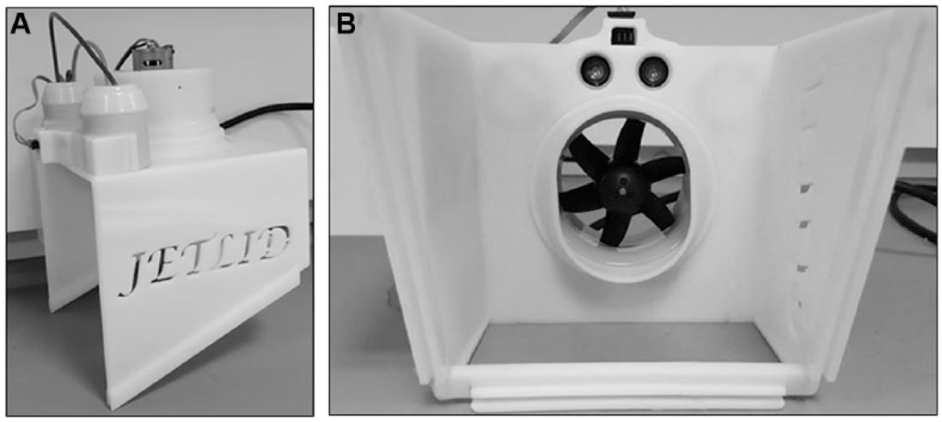
JetLid unit. (
The JetLid microcontroller firmware is diagrammed in Figure 3 . The Arduino microcontroller reads the ultrasonic sensor every 50 ms and calculates a rolling average of five readings to determine if a plate has been presented to the unit by the robot arm. When a plate is detected, the ESC turns on the fan for 7 s to create a vacuum above the lid plate. The lid rises until it meets the bottom of the fan shroud and is held there while the robot arm retracts the now de-lidded plate. The fan turns off and the lid drops to a chute that directs it to a waste receptacle. The microcontroller waits 5 s before it begins monitoring the ultrasonic distance sensor again, giving the recently removed lid ample time to be out of sensing distance before the system reengages.
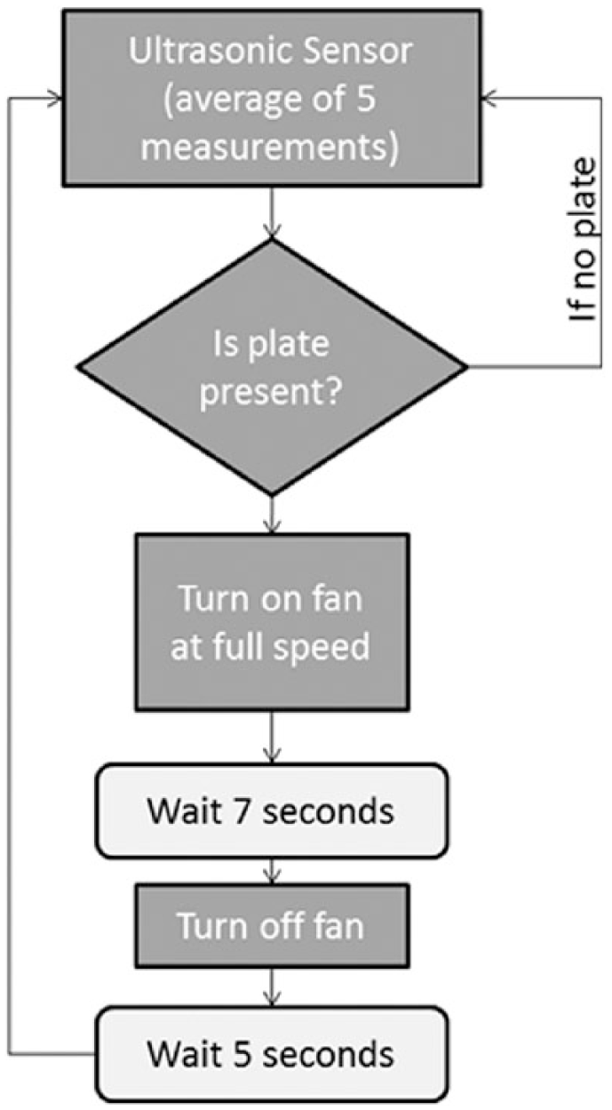
JetLid firmware logic. The ultrasonic sensor monitors until the average of five readings shows the presence of a plate. When a plate is detected, the fan engages for 7 s. This is followed by a 5 s delay before the system resets to prevent premature retriggering of the system.
Results
The JetLid device met our design goals of quickly and reliably de-lidding microtiter plates as an essential and heavily used part of one of our high-throughput screening systems. After 5 years of service, it has successfully de-lidded at least 25,000 plates with only two failures. At a cost of less than $200, we could easily justify making a backup unit in case our original unit should ever fail. As one of our earliest engineering projects using 3D printing, it quickly demonstrated the flexibility and speed of in-house 3D printing as part of creating a new device.
TipWaster
Background
We recently purchased a Lynx LM1200 liquid handler from Dynamic Devices (Wilmington, DE). While the deck has an opening for discarding used tips to a waste bin below, we soon discovered that using this opening would require us to move the machine to cut a hole into the tabletop. Additionally, we found that the table had a structural beam directly below the position where the hole would be cut. Even with a hole cut in the table, the beam would interfere with the path of the tips after they were ejected from the pipetting head. We considered moving the structural beam or sourcing a new table, but both of those options would require moving the several-hundred-pound unit and an additional delay in putting the system in operation. We recognized that the narrow gap (3.8 cm between the top of the table and the underside of the LM1200 deck) might give enough room through which the tips could exit the system. Our design requirements were guided mainly by the spatial constraints (i.e., the size of the deck opening, and the small gap between the tabletop and the bottom of the LM1200).
Design and Build
The waste cutout is positioned in the rearmost row of deck positions in the LM1200 and only about 12.5 cm from the rear edge of the table. We needed a solution that would transport the tips laterally 12.5 cm but could only be 3.8 cm tall. We considered a conveyor belt that might transport the tips, but that solution seemed overly complicated and would be challenging to implement when only 3.8 cm of height was available. We also considered an arm (or set of arms) that could sweep the tips along a channel, but again that design seemed difficult to implement in such a tight space and with many moving parts would be more prone to failure. While we liked the idea of a simple ramp, we did not expect it would work because the slope is too gentle for gravity alone to cause the tips to roll down the ramp. We needed something small that would move the tips without involving complex mechanisms prone to failure.
We finally decided to use an enhanced ramp design to solve this problem ( Fig. 4 ). Even though the slope of the ramp was only 7°, we added two small vibrational motors to the ramp that helped transport the tips down the gentle slope (RB-Spa-1202; RobotShop, Mirabel, QC; www.robotshop.com). The ramp itself was suspended on springs so the entire ramp would vibrate when the motors were triggered. We found that the combination of the slight slope and the vibrational movement was enough to shake the tips down the chute to a waste bin below. This solution was mechanically simpler (fewer moving parts) than our other ideas and could be implemented in the tight space available.
TipWaster unit. (
The device was designed in CAD software and printed on our Objet24 3D printer. In addition to the ramp, the device uses the same ultrasonic presence sensor as we used on the JetLid (HC-SR04). When tips are to be ejected, the pipet head moves directly above the deck cutout, triggering the TipWaster presence sensor. The connected Arduino then triggers the vibrational motors attached to the bottom of the ramp. They run for 7 s, allowing all the tips to travel down the ramp to an acrylic chute that directs them to a waste bin below.
Results
The TipWaster device has proven to be a robust solution, especially given the tight spatial requirements for this project. In many ways, it is similar to the JetLid, with a presence sensor, Arduino microcontroller, and 3D printed structural elements. Because ejecting tips to waste is a fairly infrequent event compared with the total time the Lynx is in operation, we favored a design that would be activated by a sensor only when needed. Also, the entire system operates independently of the Lynx control software. As an autonomous solution, it could rapidly be adapted to other systems if necessary as its operation is not dependent on a driver or communication with the Lynx. The total cost for the device was approximately $150.
Remote Monitoring Device
Background
Many pieces of equipment in our high-throughput screening laboratory either consume bulk liquid reagents or produce liquid waste. In many cases, liquid consumption or production occurs gradually over a period of time as part of large screening systems. The slow rate of liquid consumption or production sometimes leads to users forgetting to manually monitor liquid levels, resulting in the depletion of reagents or liquid waste levels overflowing their containers. Reagent depletion can lead to failed experiments, resulting in the loss of costly consumables and delayed timelines. Waste overflow can potentially void experiments, create unsafe work conditions, and put other equipment at risk of flooding or contamination. To prevent these kinds of incidents, an automated system (REMIND) was designed, built, and implemented to remotely monitor liquid level and alert users when levels go outside specified safe ranges. This system functions by deploying low-cost monitoring nodes at each liquid container that wirelessly report to a central server. The server is responsible for displaying current information and configuration values in a web interface and notifying users via email when thresholds have been exceeded.
Design and Build
While there are many liquid sensor solutions on the market, there are very few fully integrated solutions. Our primary design considerations concerned the method of liquid-level detection, remote reporting of liquid levels to a central location, user accessibility via an intuitive interface, and automated alert notifications.
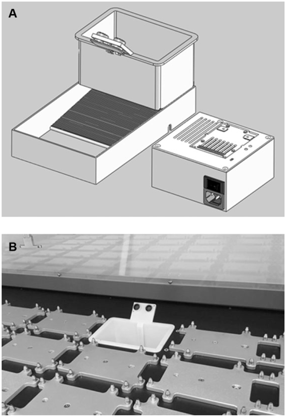
The success of the project depended on identifying a robust, yet flexible, way to accurately measure liquid levels in a variety of different bottles and carboys. While liquid level could be detected within the bottle (e.g., using a float, ultrasonic liquid height determination, or capacitance), we found that using a scale to measure vessel weight gave us the greatest flexibility and avoids any possibility of incompatibility between the sensor and the liquid being measured. A postal scale with an external display (SE-50; American Weigh Scales, Norcross, GA) provided a solution where the sensor output from the scale could be directed into the REMIND communication node ( Fig. 5A ). The weights of the empty vessel and completely filled vessel were recorded as reference points.
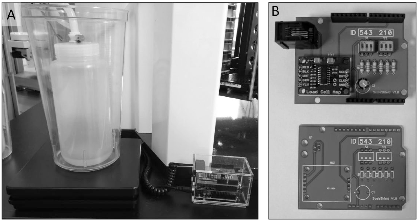
REMIND node hardware. (
Because the liquid reservoirs are distributed throughout the lab, the ability to transmit liquid-level data wirelessly was also a significant design consideration. We first considered WiFi for communication, but neither creating an ad hoc wireless network nor using the existing corporate WiFi network was compatible with our IT security policies. We finally chose to use RF to communicate between each REMIND node and the RF Server.
Connected to the scale, each REMIND node consists of three elements housed in an acrylic enclosure: an Arduino UNO microcontroller, an RF board (RFD21815; RF Digital, Hermosa Beach, CA), and a custom printed circuit board (PCB; Fig. 5B ). The PCB has the RJ9 jack used for communication to the scale, an analog/digital converter (HX711; AVIA Semiconductor, Xiamen, China), and DIP switches that are used to assign each device a unique identifier. The Arduino UNO microcontroller implements a simple firmware that reads the scale values continuously into a circular buffer from which a running median is calculated. We found this more robust than taking single readings or even running averages that could be skewed by occasional outlier data points. Upon request from the RF Server, the Arduino converts the running median into JSON format for transmission. The RF board broadcasts the values to the central RF Server made up of a PC with an RF USB dongle (RFD21807; RF Digital). The RF board was chosen for its data integrity features and easy integration with the Arduino microcontroller.
To handle communication between the RF Server and the various nodes, we wrote an application in Node.js runtime, called RF Broker, and deployed it to the RF Server PC. Because all nodes share a common RF channel, the RF Server is responsible for requesting data from one node at a time to avoid nodes transmitting over each other. Each node is assigned a specific ID, which is set using DIP switches on the PCB. Because all nodes share a common RF channel, transmissions from the RF Server are received by all the nodes. The data are sent in the following format:
If a node receives a data packet with an ID intended for a different device, it is simply ignored. Each message packet is assigned a unique ID. RF communication is prone to interference and dropped packets, so the RF Broker waits for a response for each message ID before moving on to the next message. After three communication failures (i.e., lack of response from the node), the RF Broker will move on to the next message.
The range of RF is inherently limited, especially in a low-power implementation like this one. This presented a problem because we needed the ability to deploy nodes across multiple labs or floors in our building. To solve this problem, the system supports multiple RF Broker instances. If a node is needed outside the currently implemented range, another instance of RF Broker can be started on another PC with its own RF receiver module. All the data from all RF Broker instances are collected into one database by the web server over a web socket connection ( Fig. 6 ).
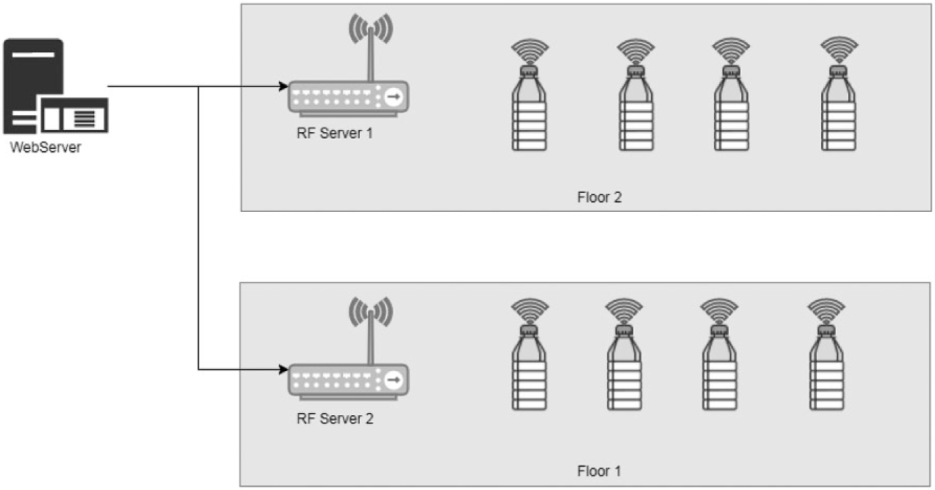
REMIND architecture. Each REMIND node (symbolized by a bottle) communicates with an RF Server within range. The RF Servers then relay node status to the central web server.
Another important design consideration was the user interface that users would use to accomplish the following tasks: add or remove nodes, monitor current liquid levels, configure acceptable liquid ranges, and set up notification alerts. Because the system would be used by several scientists in our department and could potentially be deployed to other departments, an intuitive, user-friendly interface was considered critical. We decided to implement a web-based solution because of the ease of accessibility (via web browser) and management (as opposed to a stand-alone application that would have to be deployed to and maintained on several PCs).
The web server is written in Node.js with a MongoDB document store. It exposes a REST API to allow the web front end and the RF Server to interface with the document store. It also operates two web socket interfaces. The first web socket interface is a connection with the RF Server(s). When the web server receives a new message from an RF Server, it stores the results in the database. The second web socket interface pushes real-time liquid-level updates to all connected web clients. If the results are outside the acceptable range for that node, an email is sent to the configured users. The web server continues to send notification emails to users for any nodes that remain out of range at preconfigured intervals.
The web interface can be seen in Figure 7 . It is written in JavaScript using Knockout.JS and jQuery. It provides a dashboard view to monitor the entire network of REMIND nodes ( Fig. 7A ) and detail views for each bottle or carboy ( Fig. 7B ). Adding or removing nodes and configuring email alerts is also done through the web interface.
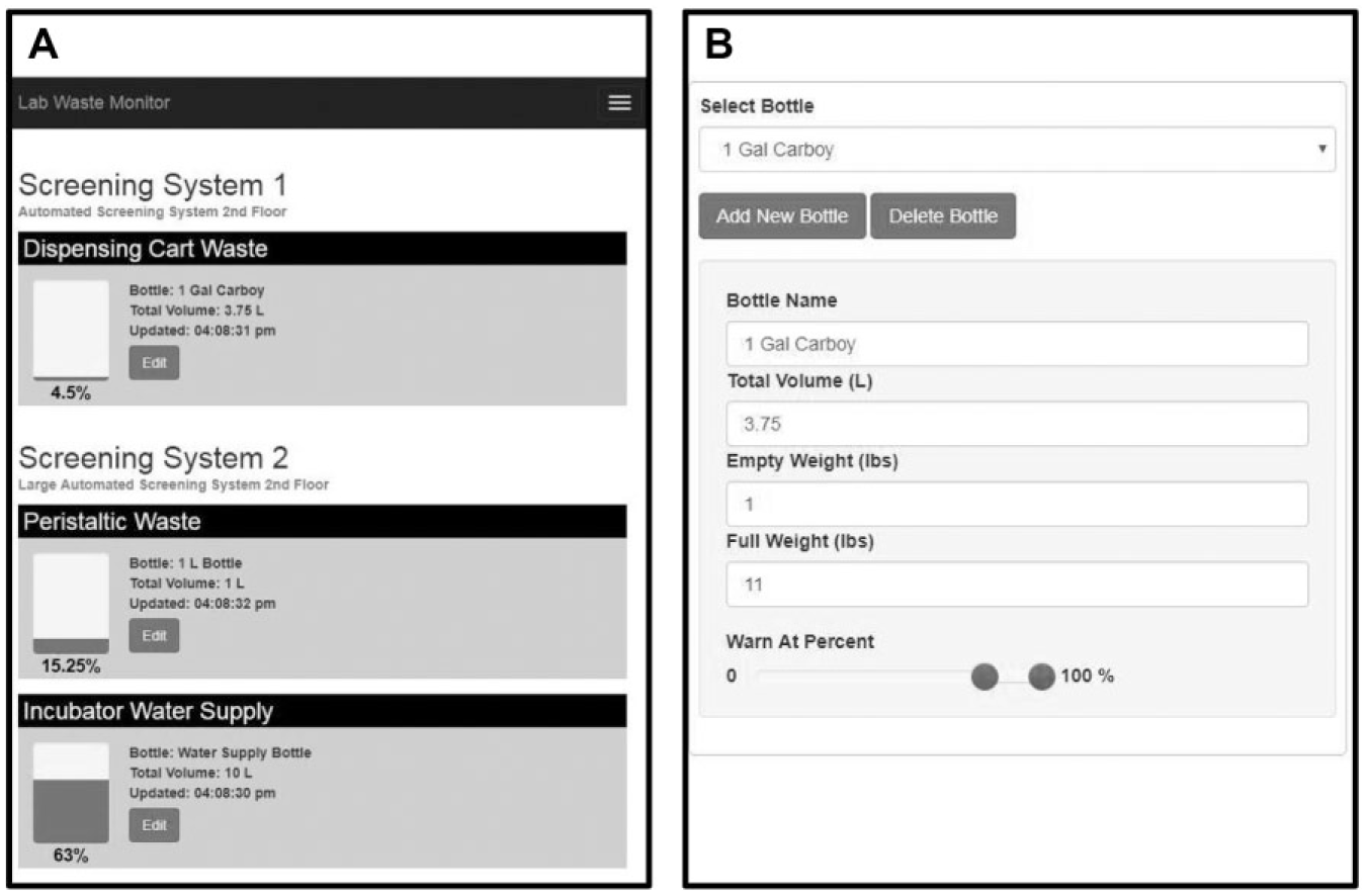
REMIND user interface. (
Results
The REMIND platform met our design goals of measuring liquid levels in various bottles and carboys, reporting these results to a central database, allowing users convenient access to these data, and alerting users when liquid levels cross predefined thresholds. The component cost for each node is approximately $65. Overall, the system has proven very robust with no failures during 15 months of use across several monitoring nodes. It has successfully alerted users when liquid containers go out of range, thus preventing costly errors and hazards. The system is very easy to configure and expand through the developed web interface. All nodes share one common RF channel, which provides sufficient bandwidth for up to 100 nodes but could eventually result in a bottleneck. If this is ever an issue, a second version could be implemented using channel multiplexing.
Conclusions
The challenges of operating automated systems in a drug discovery lab have provided many opportunities to design, test, and build custom-engineered devices. While we, and others, have been doing this for years, the availability of in-house additive manufacturing (3D printing) and relatively simple, inexpensive microcontrollers (Arduinos) has enabled us to make both stand-alone solutions and more complex, networked solutions.
One of the most powerful, enabling consequences of these technologies is the rapid development time for these devices. Initially, development time for simple devices would be on the order of 1–2 months, but in many cases, this can be shortened to a few days or a couple of weeks. Also, complex projects are less daunting when shorter iteration cycles can be achieved, mainly through the speed of 3D printing parts in-house, rather than waiting on outsourced manufacturing. For simple projects, a solution can often be produced the same day.
We have described two stand-alone devices, JetLid and TipWaster, that both use 3D printed housings and parts and are controlled by Arduino microcontrollers. The wealth of input devices and sensors for microcontrollers gives great flexibility in the ability to monitor temperature, light, humidity, presence, motion, switch states, and user input. The Arduino IDE is readily accessible to enthusiasts, allowing the creation of firmware to monitor inputs and control outputs. Likewise, small electronic components (in these cases, high-speed fans and vibrational motors) are relatively inexpensive and readily available. Together, these technologies have been transformative.
We also described our first project, REMIND, that embraces the idea of the “Internet of things.” Connectivity of devices with PCs and people gives additional flexibility and power to solutions. In this case, we took the relatively mundane task of monitoring liquid levels in bottles and carboys and automated it. REMIND has so far been implemented only for the task of monitoring liquid levels, but the power of the platform is that anything that can be measured by an electronic sensor can be implemented in the REMIND framework. The REMIND node, RF Server, and Web Server will remain largely the same, but the sensor attached to the node will change. For instance, a temperature sensor could be attached to the node instead of a scale. The temperature sensor could be placed in a refrigerator, freezer, incubator, or anywhere else where monitoring temperature is critical. The RF Broker would regularly poll the node and write the data to a common database from which it would be served to the web. In its current implementation, these data become available to users and can trigger simple alerts (email notifications), but in future implementations it could trigger more complex outcomes and even be tied into other systems. With the enabling power of 3D printing, wireless communication, and microcontroller technologies, there are seemingly endless opportunities to bring smart, connected devices to drug discovery laboratories.
Footnotes
Acknowledgements
We gratefully acknowledge our colleagues across Takeda’s Oncology Drug Discovery Unit for productive collaborations such as those described in this article. We also thank Saurabh Menon for his critical reading of the manuscript and support of these projects.
Declaration of Conflicting Interests
The authors declared no potential conflicts of interest with respect to the research, authorship, and/or publication of this article.
Funding
The authors received no financial support for the research, authorship, and/or publication of this article.