
Abstract
Typography-like templates for polydimethylsiloxane (PDMS) microfluidic chips using a fused deposition modeling (FDM) three-dimensional (3D) printer are presented. This rapid and fast proposed scheme did not require complicated photolithographic fabrication facilities and could deliver resolutions of ~100 μm. Polylactic acid (PLA) was adopted as the material to generate the 3D-printed units, which were then carefully assembled on a glass substrate using a heat-melt-curd strategy. This craft of bonding offers a cost-effective way to design and modify the templates of microfluidic channels, thus reducing the processing time of microfluidic chips. Finally, a flexible microfluidic chip to be employed for cell-based drug screening was developed based on the modularized 3D-printed templates. The lithography-free, typography-like, 3D-printed templates create a modularized fabrication process and promote the prevalence of integrated microfluidic systems with minimal requirements and improved efficiency.
Introduction
During the past several decades, microfluidic chips have contributed to outstanding breakthroughs and have facilitated the development of a new era of drug screening.1–3 Compared with the traditional screening method based on microplates, microfluidic chips offer a more cost-effective, high-throughput technique due to their distinctive abilities to handle very small quantities of fluid and to provide a well-defined microenvironment of fluid field, which enables vast amounts of parallel drug assays conducted with a few cells, resulting in huge savings in the cost of reagents, targets, and compounds.4–6
However, the traditional fabrication process of microfluidic chips mainly relies on the technology of lithography-based micromachining, 7 which, despite the advantages of high resolution and reproducibility, has the critical drawbacks of a long cycle, a complex process, and the necessity of expensive facilities. Therefore, people have been devoting their efforts toward the alternative lithography-free methods of microfluidic chips.8–10 In recent years, additive manufacturing, also known as three-dimensional (3D) printing, has caused a revolution in the manufacturing of microfluidic chips. 11
The rapid development of the 3D printing technique has produced two main modes of applying 3D printing in microfluidic fabrication. One is to directly print microfluidic chips, 12 and the other is to print their templates, 13 followed by the pouring and molding of chip-building materials. Limited by the printing materials and curing methods, direct printing usually produces rigid monolithic microfluidic systems of large scale. The performance of microfluidic systems can be affected by changes in the operation’s surroundings or poor design, which may result in unnecessary costs. 14
On the other hand, the 3D-printed templates can be adapted as functional modular units able to be assembled into a completed system and reused in different designs. By printing the templates of microfluidic chips and molding them with polydimethylsiloxane (PDMS), known to be the most popular material in lab-on-a-chip (LOC) applications, the excellent properties of PDMS, such as its biocompatibility, translucence, flexibility, inexpensiveness to produce, and easiness to mold, can be retained. Furthermore, versatile customization of complex microfluidic systems with the reduction of time and cost is achieved.15–18
In this paper, the polylactic acid (PLA) template units for PDMS microfluidic chips were prepared using a fused deposition modeling (FDM) 3D printer. As a biodegradable and bioactive thermoplastic aliphatic polyester, the PLA template units of various functions were easily connected and reorganized through a heat-melt-curd strategy. As an example, the PLA template units for a drug screening microfluidic chip were designed and assembled on a glass slide. After molding the template with PDMS, the drug screening microfluidic chips were used to culture tumor cells under different drug concentrations, which were determined by mixing cisplatin and buffer in the designed all-PDMS microfluidic system. The present technique enables the fabrication of complex microfluidic devices with minimal fabrication requirements, improves the efficiency of LOC fabrication, and provides a versatile development technique for flexible chips.
Materials and Methods
Materials
Fluorescent dyes (Fluka, Shanghai, China), phosphate-buffered saline (PBS; pH 7.4; Radnor, PA), and CCK-8 (Dojindo, Tokyo, Japan) were used in this study. Cisplatin (TopScience, Shanghai, China), as a common chemotherapeutic used to treat a number of cancers, was involved as an illustration. Formlab standard clear resin and PLA were complimentary obtained along with the purchase of the FDM 3D printer (PrintRit, Guangzhou, China). PDMS and its curing agent were purchased from Dow Corning GmbH (Midland, MI).
The tumor cells (A549) were cultured at 37 °C and 5% CO2 in Dulbecco’s modified Eagle’s medium (DMEM) with 10% fetal bovine serum and 15 mL/L antibiotic solution (penicillin–streptomycin solution). The culture media was changed every other day. Before experiments, the tumor cells were taken from flasks and diluted with DMEM to the required concentrations after centrifugation.
FDM 3D-Printed Templates for the Fabrication of Drug Screening Microfluidic Chips
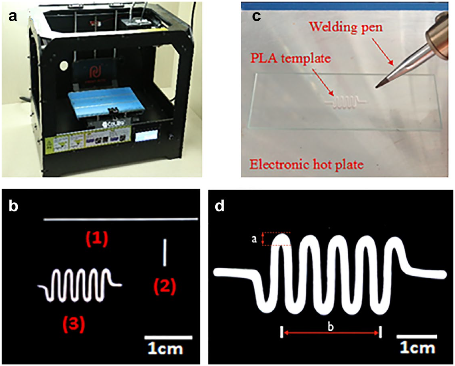
A commercial FDM 3D printer (SmartPrint2.0) ( Fig. 1a ) was used in the study. The designed drug screening microfluidic chip was first split into basic units and plotted with CAD software ( Fig. 1b ). To print the additive material (PLA), the printing temperature was set above 155 °C. The units were printed onto a glass pane and were easily cut off from the glass pane after cooling. A coordinate paper was stuck under a glass slide or a petri dish as spatial reference to align accurately. An electronic hot plate and a welding pen were used to fix and connect the basic units together ( Fig. 1c ). The completed template was obtained after connecting all the modular units as designed and cooling in the air.
(
PDMS and its curing agent were mixed at a weight ratio of 10:119 under stirring. After degassing for 20 min and removing bubbles, the PDMS mixture was poured over the completed template and cured in an oven at 80 °C for 1 h to form molds. PDMS molds should be stripped from the 3D-printed PLA templates under the optimal conditions. Finally, the PDMS molds were treated with oxygen plasma (Harrick Plasma Inc., Ithaca, NY) for 1 min to activate the silicon–oxygen bonds on their surface and were bonded together. To strengthen bonding, the developed microfluidic chips were stored at 80 °C for another 10 min.
The heating temperature and time greatly influenced the PLA template deformation. Therefore, the optimal conditions of template bonding had been explored based on a large serpentine template unit of 2.5 cm in width and 7.5 cm in length ( Fig. 1d ). The large template unit was placed on a glass slide and heated by an electronic hot plate from 140 to 220 °C for 1 min at each temperature. The pictures taken every 5 s were collected in order to find the variation tendency of the PLA template attached to the glass substrate.
Fluorescent dyes diluted with PBS were used to characterize the drug screening microfluidic chip. They were injected into the microfluidic chip at 20 μL/h with a syringe pump (LSP04-1A, LongerPump, Baoding, China) to generate a gradient concentration. Before each injection, all microchannels in the chip were filled with PBS buffer.
Cell Viability Study in the Drug Screening Microfluidic Chip
Before tumor cell loading, the microfluidic chip device was autoclaved at 135 °C for 30 min and sterilized by UV light overnight. Cell culture medium was continuously injected into the chip at 20 μL/h until all the microchannels were filled. To seed tumor cells into each culture chamber, 200 μL of DMEM solution containing cells at a density of 1 million/mL was directly added into the open chamber. The microfluidic chip was kept at 37 °C and observed every 12 h until the cells became confluent in the chambers. Finally, 0.1 μg/mL cisplatin in DMEM was injected at 20 μL/h from the other inlet, while cell culture medium was continuously injected into the microfluidic chip at 20 μL/h. Twenty-four hours later, cell images were taken and live cell numbers were compared between each chamber.
Results and Discussion
Bonding Efficiency and Deformation of PLA Templates
After the pouring and molding of PDMS at 80 °C, a critical step is to peel the PDMS molds off of the PLA-attached glass substrate without destroying the templates, which depends on the delicate balance between the PLA–substrate bonding efficiency and the PLA module deformation under an optimal heating temperature of the glass pane and the time.
Therefore, a parameter (ΔS) is defined to calibrate the PLA module deformation:
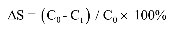

where b is the length of the template and a is the width of the peak structure as shown in Figure 1d . C0 is the initial b/a ratio when no heating is applied, and Ct is the b/a ratio at a certain temperature after heating for t seconds.
As we observed, the commercial PLA printing materials started to melt at 150 °C. Figure 2 showed the variation tendency of ΔS when the temperature was increased from 140 to 220 °C and the heating time ranged from 0 s to 60 s. When the temperature of the glass pane was kept around 180 °C, the PLA templates of the design shape were well attached to the glass substrate within 30 s. When heating was stopped, the PLA templates were easily removed from the cold glass pane. However, at even higher temperatures or longer times, deformation of the PLA templates occurred, which obviously not only impacted the microscopic shape of the microfluidic channels but also destroyed the reliability and reusability of the PLA templates. The yellow curve in Figure 2 exhibits the optimal conditions to keep the PLA templates attached to the glass pane without deformation (ΔS < 5%). Therefore, in this study, the PDMS molds were peeled off from their templates as soon as the PLA templates were bonded to the glass at 180 °C for 25 s.
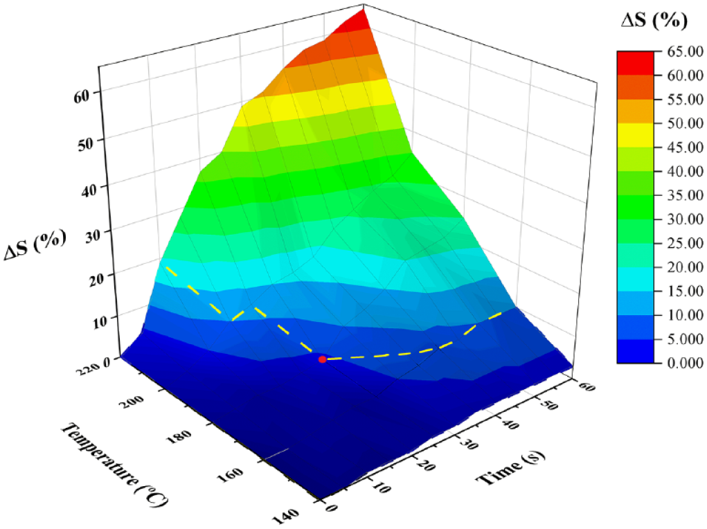
Color distinction graph of the PLA module deformation. ΔS was calculated to describe the deformation degree of the PLA template on a glass slide at a heating temperature ranging from 140 to 220 °C and a time from 0 to 60 s. The region lower than the yellow curve shows that the PLA modules could not firmly adhere on the glass substrates. Therefore, the red dot was chosen as the optimal conditions in this study. The PDMS molds were peeled off from their templates as soon as the PLA templates on glass were heated at 180 °C for 25 s.
Viability of Tumor Cell and Drug Screening on Microfluidic Chips
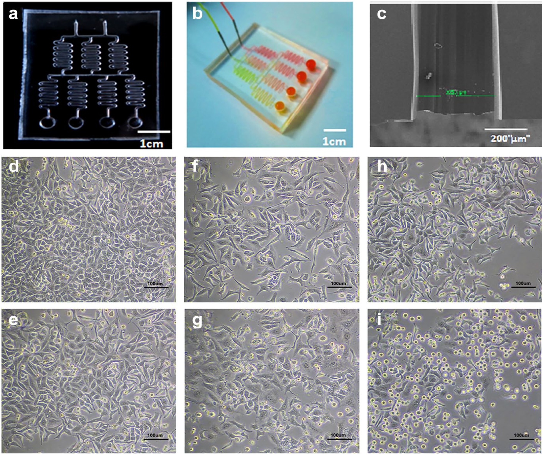
Under the optimal conditions mentioned above, several 3D-printed PLA modules were prepared and assembled together to produce a complex template for concentration gradient generators ( Fig. 3a ) with open chambers as the outlets. The serpentine units were 0.75 cm in width and 1.75 cm in length. The diameter and height of the outlet chambers were each 0.5 cm. The SEM image shows that the diameter of the microchannel after PDMS replication was measured as 355 μm ( Fig. 3c ).
(
After plunging two separate streams of dyes at 20 μL/h for 3 h, Figure 3b shows an obvious progressively diluted effect in the microfluidic chip generating four mixing ratios at the outlet chambers. The further from the inlets, the lower the concentration of the dyes in the microchannel. A more diluted and mixed solution is attainable by constructing more linear and serpentine units. The gradient profile depends on several factors, such as the concentration of solutions, the design of the channel, and the flow rate. The side-by-side laminar flow is dominant inside a microchannel where mixing across the streamlines is achieved by molecular diffusion only and predicted accurately. 19 Concentration gradients automatically produced in microfluidic chips have great benefits in high-throughput drug screening. 20
After successfully loading tumor cells in the open chambers, 0.1 μg/mL cisplatin in DMEM and cell culture medium was injected from the two inlets separately. During the 3 h injection, excess liquid leaking from each chamber was carefully removed with micropipettes. The drug screening microfluidic chip was then kept in an incubator at 37 °C for 24 h. The cell images from each chamber were taken and compared with the live cell number before dosing.
Taking cisplatin as an example, the drug screening capability of the developed microfluidic chip was evaluated by monitoring the cell growth before and after dosing. To have a better grasp, the pseudocolor operation was run by a computer-assisted program to distinguish live and dead cells. The tumor cells in the first chamber containing mostly cell culture medium grew commonly ( Fig. 3d,e ) after 1 day. The last chamber containing cisplatin of the highest concentration had a scant amount of live cells ( Fig. 3h,i ) after 24 h of incubation. Cell viability in the second chamber was in between the two chambers mentioned above due to the drug concentration gradient generated automatically in the designed microfluidic chip.
Besides the planar structure, the 3D-printed templates also easily enable the alignment of several layers and accomplish more complicated 3D structures. Unlike other molds developed by technologies such as photoresist, stereolithography, and computer numerical control machines, the 3D-printed modules are reusable and reassembled within 5 min, with an average cost of only $0.08 USD. The flexible 3D-printed templates create a modularized fabrication process and promote broader access to establish the integrated microfluidic systems with minimal requirements and improved efficiency.
Conclusion
A method for the rapid customization of integrated microfluidic chips has been introduced in this paper. Being similar to the process of typography, the method entails the templates of specific functional modules being 3D-printed separately and assembled together via a heat-melt-curd strategy to form a completed microfluidic chip. The 3D-printed templates of microfluidic units offer a cost-effective way to redesign and rebuild the microfluidic channels, to modularize the templates, and to accelerate the fabrication process.
Many alternative automatic, high-throughput, lithography-free methods, such as paper-based fabrication, near-field electrospinning, and rapid prototyping, have also been rapidly developing. Owning to the great potential of microfluidic systems in drug screening and clinic tests, there will be more and more efforts to simplify microfluidic device fabrication in the future.
Footnotes
Declaration of Conflicting Interests
The authors declared no potential conflicts of interest with respect to the research, authorship, and/or publication of this article.
Funding
The authors disclosed receipt of the following financial support for the research, authorship, and/or publication of this article: This work was supported by the Medical-Engineering Cross Foundation of Shanghai Jiao Tong University (grant nos. YG2017QN52, ZH2018QNA54, ZH2018QNA49, and ZH2018ZDA01).