
Abstract
This article describes an integrated platform for the on-chip exchange of the continuous phase in droplet microfluidic systems. The drops used in this work are stabilized by amphiphilic nanoparticles. For some characterizations and applications of these nanoparticle-stabilized drops, including the measurement of adsorption dynamics of nanoparticles to the droplet surface, it is necessary to change the composition of the continuous phase from that used during the droplet generation process. Thus far, no work has reported the exchange of the continuous phase for a large number (>1 million) of drops in a microfluidic system. This article describes the design and characterization of a high-efficiency and high-throughput on-chip exchanger of the continuous phase in a continuous-flow droplet microfluidic system. The efficiency of exchange was higher than 97%. The throughput was greater than 1 million drops/min, and this can be increased further by increasing the number of parallel exchangers used. Because drops are injected into the exchanger in a continuous-flow manner, the method is directly compatible with automation to further increase its reliability and potential scale-up.
Introduction
Droplet microfluidics has enabled a wide range of applications from digital PCR 1 to the assembly of novel nano- and microstructures.2,3 The success of the technology has hinged on a single type of surfactants consisting of a perfluorinated polyether (PFPE) tail and a polyethylene glycol (PEG) head group (PFPE–PEG) to stabilize the drops against coalescence. 4 The fluorinated tail is necessary because the continuous phase typically comprises a fluorinated solvent, which is used due to its biocompatibility and gas permeability. 4 PFPE–PEG surfactants have multiple limitations, however, including their synthetic complexity and the surfactant-mediated cross-contamination of droplet contents.5–7 To overcome these limitations, we have recently reported the use of partially fluorinated silica nanoparticles (referred to as F-SiO2 NPs) to replace surfactants as droplet stabilizers.8–10 Our particles have the following advantages: (1) their synthesis is simple and scalable; (2) they are effective in stabilizing droplets in various fluorinated solvents as the continuous phase against coalescence under typical droplet manipulation conditions; (3) they prevent interdrop molecular transport and the cross-contamination of droplet content; and (4) their surfaces can be modified to contain reactive groups, such as amines, for further conjugation with various “designer” molecules.
In some characterizations and applications of these particles, we found it necessary to change the continuous phase after the drops were generated. For example, to verify and visualize that the particles possessing new surface chemistries remain amphiphilic, we have attached fluorescent labels to the particles. 10 After replacing the continuous phase—originally containing a suspension of fluorescent NPs—with neat oil, the presence of a fluorescent rim around the drops would indicate that the particles were successfully adsorbed to the droplet interface. In addition, the measurement of the rheology of these particle-laden drops and the adsorption dynamics of NPs of different sizes or surface chemistries to the droplet interface could require the continuous phase to be changed from that when the drops were first generated.
Previously, we have exchanged the continuous phase of our NP-stabilized drops by pipetting out the fluorinated oil from the bottom of the Eppendorf tube in which the emulsion was stored, followed by adding a new oil to this tube. 9 The new oil was then mixed with the drops by pipetting the emulsion up and down. The process was repeated until the degree of oil exchange was sufficient for the desired application. This manual off-chip oil exchange procedure has multiple disadvantages, however: (1) it is difficult to control the timing of the exchange for the subsequent quantification of the dynamics of adsorption or transport phenomena across the droplet interface; (2) the method is labor-intensive and cannot be scaled up easily to handle increased volumes of liquids; (3) a portion of the drops is lost as they adhere to the wall of the container or the pipette tip; and (4) the drops can be subject to coalescence or breakup when manipulated using a pipette because it is difficult to control the applied pressure from the pipette.
For a small number of drops (<103), it is possible to anchor individual drops in a droplet trap11–13 and change the continuous phase by flowing a new oil into the channel. It becomes difficult, however, to anchor every droplet as the number of drops increases (>106). To our knowledge, no work has reported the change of the continuous phase in an emulsion consisting of a large number of suspended drops directly in a microfluidic system.
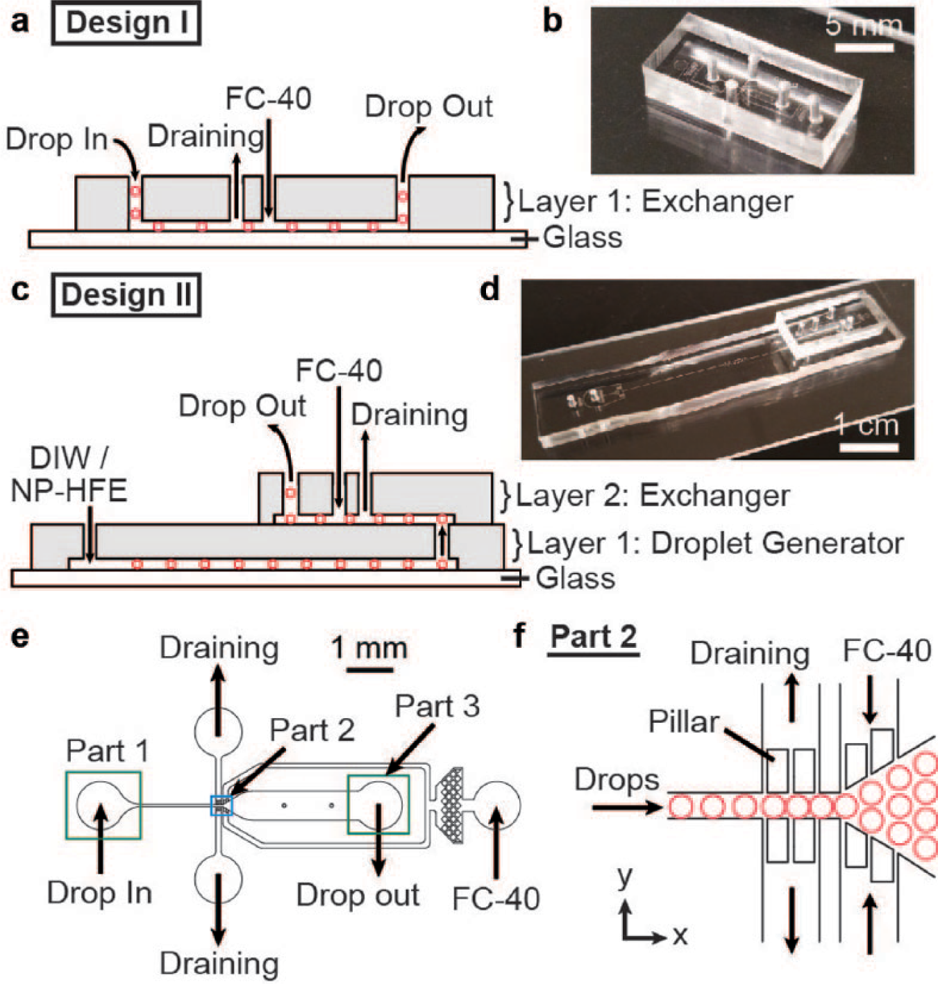
Here, we describe an integrated microfluidic device for the high-efficiency and high-throughput on-chip exchange of the continuous phase after the drops are generated. We demonstrate two designs: Design I uses a standalone exchanger for exchanging the continuous phase of an emulsion that has been previously generated and incubated off-chip. This design is intended to operate in a high-throughput manner. Design II uses an on-chip exchanger integrated directly downstream of a droplet generator. In this design, because every step is performed within an enclosed microfluidic channel, and there is no need to transfer drops in and out of the microfluidic system, the loss of drops is minimized, and the drops are protected from coalescence or contamination caused by manual pipetting. In both designs, because drops are injected into the exchanger in a continuous-flow manner, our method is compatible with automation to further increase its reliability and potential scale-up. We believe that our method can also be useful to other applications. Examples include the study of liquid–liquid extraction and molecular transport among drops,8,14–17 the measurement of the adsorption dynamics of NPs to liquid–liquid interfaces and the related rheological properties, 18 and the fabrication of opal and inverse-opal structures. 19
Materials and Methods
Fabrication of Microfluidic Devices
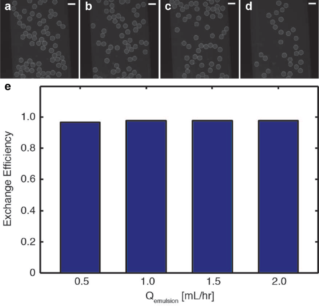
We fabricated all devices in poly(dimethylsiloxane) (PDMS) using standard methods in soft lithography.20,21 For Design I (
Figure 1a
(
Generation of Droplets
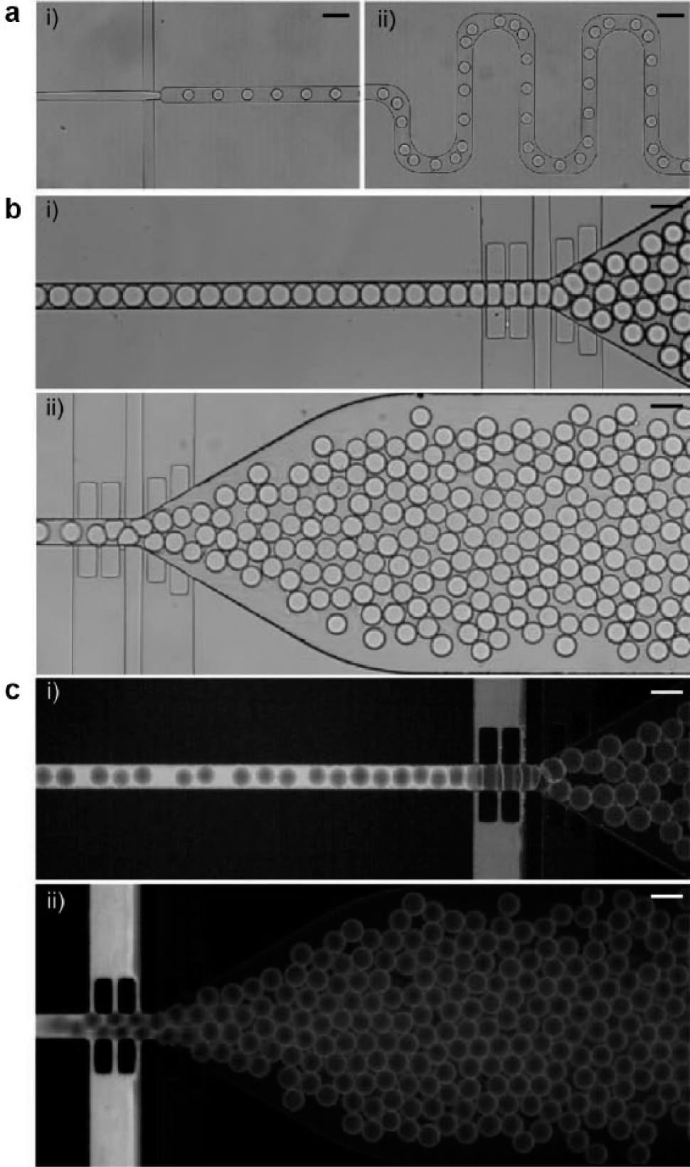
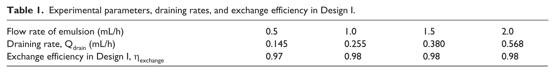
We used a flow-focusing nozzle for the generation of NP-stabilized drops ( Figure 2a ). 22 The disperse phase contained deionized water. The continuous phase contained a suspension of 100 nm F-SiO2 NPs doped with rhodamine B (6% w/w) in HFE-7500. 10 Rhodamine B facilitated the characterization of the efficiency of the subsequent exchange of the continuous phase by using simple fluorescence microscopy. In Design I, the volumetric flow rates for the disperse and continuous phases were 0.2 and 0.4 mL/h, respectively, during the droplet generation process. All flows were driven by syringe pumps. The mean drop size was 85 pL, and the volume dispersity of the drops was less than 3%. We incorporated a serpentine channel (a total length of 1.37 cm, corresponding to a droplet transit time of ~0.21 s at a flow speed of ~6.53 cm/s) downstream of the droplet generator to allow additional time for the NPs to adsorb to the droplet interface ( Figure 2aii ). We collected the drops in a 3 mL syringe via a polyethylene tubing. While collected in the syringe, the drops creamed to the top of the syringe to reach a droplet volume fraction of f ~70%. Creaming occurred because the drops had a density lower than that of the continuous phase. This concentrated emulsion was then reinjected into the exchanger separately. Table 1 lists the reinjection flow rates used. In Design II, the generated drops flowed directly to the exchanger after passing through the serpentine channel. Table 2 lists the volumetric flow rates for the disperse and continuous phases used for droplet generation. Direct bonding of the two layers eliminated the need for tubing to transfer the drops.
Droplets flowing in the device. (
Experimental parameters, draining rates, and exchange efficiency in Design I.
Experimental parameters, droplet sizes, draining rates, and exchange efficiency in Design II.
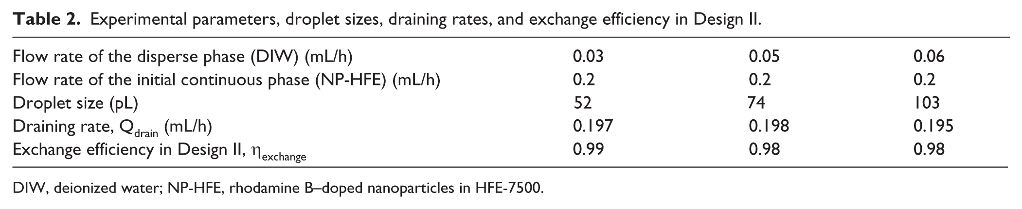
DIW, deionized water; NP-HFE, rhodamine B–doped nanoparticles in HFE-7500.
Design of the Exchanger
The exchanger was designed to replace the initial continuous phase with a new continuous phase. For the demonstration of principle, we used neat FC-40 as the new continuous phase to replace the initial continuous phase consisting of the rhodamine-doped NP suspension in HFE-7500. Other oils can also be used as the new continuous phase as long as they do not destabilize the drops. The exchanger consisted of three basic parts (
Figure 1e
Part 1. An inlet where drops were injected from an external container (e.g., syringe) in Design I, or from the integrated droplet generator in Design II.
Part 2. An exchanger comprising: (2a) draining channels consisting of side channels via which the initial continuous phase—NP suspension in HFE-7500—was drained; and (2b) injection channels consisting of side channels via which the new continuous phase—neat FC-40—was injected. To ensure that only the continuous phase and not the drops were drained, we included rectangular pillars (in-plane dimensions x × y = 40 × 100 µm) between the main channel and the entrance of the draining channels. The distance between the pillars was 10 µm, about 5 times smaller than the droplet diameter ( Figures 1f , 2b , and 2c ). The height of the side channels was about half of the droplet diameter. The Laplace pressure at the entrance of the draining channels prevented the drops from entering these side channels under the applied flow conditions.23–25 The outlet of the draining channels was connected to a polyethylene tubing open to atmosphere. To quantify the draining rate, we measured the volume of the initial continuous phase (rhodamine-doped F-SiO2 NPs in HFE) in a polyethylene tubing having a known cross-section area within a certain time period.
To reduce the pressure downstream, the main channel was widened downstream of the draining channels with a diverging angle of θ = 30°. When the drops flowed past the draining channels, their volume fraction increased due to the drainage of the initial continuous phase. A high droplet volume fraction increased the fluidic resistance and the corresponding back pressure, which would cause the droplets to infiltrate into the draining channels. By widening the main channel after the draining channels, the back pressure downstream was reduced, and the undesirable infiltration of drops into the draining channels was not observed under the flow conditions tested.
Part 3. An outlet where the drops were collected for subsequent characterization.
Quantification of Exchange Efficiency in the Exchanger
Because the initial continuous phase contained rhodamine-doped F-SiO2 NPs and the new continuous phase was nonfluorescent, it was simple to quantify the efficiency of the exchange by comparing the fluorescence intensity of the continuous phase upstream and downstream of the exchanger. Figure 2c shows representative fluorescence images of the drops flowing in the exchanger. The continuous phase upstream of the exchanger appeared bright due to the fluorescence from the rhodamine-doped F-SiO2 NPs. After the exchange, the continuous phase appeared dark, indicating that most of the initial continuous phase was drained.
Results and Discussions
Exchange Efficiency in Design I
To achieve a high exchange efficiency, most of the initial continuous phase should be drained. We found that adjusting the height of the tubing from the outlet of the main channel relative to that of the tubing from the outlet of the draining channels was effective to ensure that most of the initial continuous phase was drained. For all our experiments, the ratio of the heights of the tubing from the main channel and draining channels was about 5. To keep the volume fraction of the emulsion relatively fixed before and after the exchange of the continuous phase, the injection rate of FC-40 was set to equate the draining rate of the initial continuous phase in the emulsion.
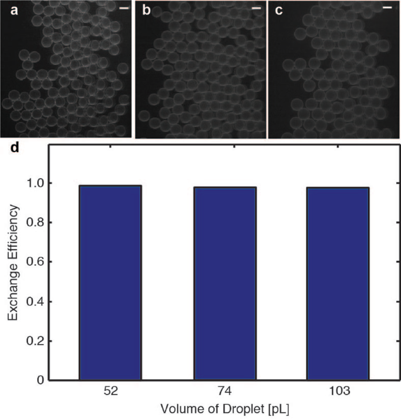
Figure 3a–3d show fluorescence images of the drops after the exchanger at different flow rates of the emulsion (also see Table 1 ). The drops had a fluorescent rim due to the adsorption of rhodamine-doped F-SiO2 NPs at the droplet surface. To quantify the efficiency of the exchange of the continuous phase, we compared the fluorescence intensity in the continuous phase upstream and downstream of the exchanger. We define the efficiency of exchange in Eq. (1):
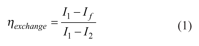
where I1, I2, and If are the fluorescence intensities of the initial continuous phase (rhodamine-doped F-SiO2 NPs in HFE), the injected continuous phase (neat FC-40), and the final continuous phase after the exchange, respectively.
Efficiency of exchange in Design I. (
Figure 3e and Table 1 show the exchange efficiency as a function of the flow rate of the emulsion. We were able to achieve a high exchange efficiency of between 97% and 98%. It was difficult to obtain 100% exchange efficiency with our design because it would require all the initial continuous phase to be drained and lead to an unstable emulsion.
Maximum Throughput of Exchange in Design I
The maximum throughput of exchange was limited by the maximum velocity at which we could flow the drops before they started infiltrating into the draining channels. At a high flow rate, drops became increasingly susceptible to breakup.26,27 The small, split drops could then enter the draining channels. With the current design, the maximum injection rate was 2 mL/h, above which the drops started entering the draining channels. The corresponding throughput of exchange was about 4500 drops/s for a single exchanger.
To increase the throughput of exchange, four exchangers were connected in parallel ( Figure 4 ). The total flow rate of the emulsion increased to 8 mL/h, corresponding to a throughput of 18,000 drops/s. The exchange efficiency was maintained at 98%. We note that the throughput can be increased further by simply increasing the number of exchangers in parallel.
Parallel on-chip exchanger. (
Exchange Efficiency in Design II
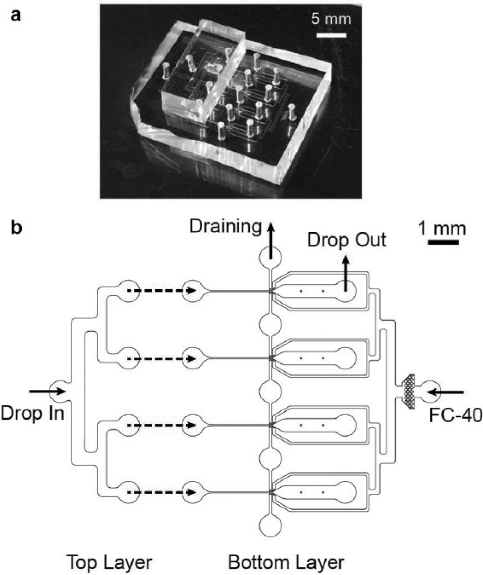
In Design II, the drops generated in the bottom layer flowed directly to the inlet of the exchanger in the top layer. The draining rate in the exchanger was slightly smaller than the flow rate of the initial continuous phase (see values in Table 2 ). To keep the volume fraction fixed before and after exchange, the injection rate of FC-40 was set to equate the draining rate. Table 2 and Figure 5 show the flow rates of disperse and continuous phases, draining rates, and exchange efficiencies for three different droplet sizes tested. The exchange efficiency was higher than 98% for all cases.
Efficiency of exchange in Design II. Microscopic images of the emulsion after exchange of the continuous phases for different droplet sizes: (
Conclusions
In this article, we demonstrated an integrated platform for the high-efficiency and high-throughput on-chip exchange of the continuous phase in a droplet microfluidic systems. The efficiency of exchange was higher than 97% in all cases tested. To increase the efficiency further, a second exchanger could be used for an additional round of drainage of the initial continuous phase followed by the injection of the new continuous phase. The throughput was more than 1 million drops/min, and it can be increased further by increasing the number of parallel exchangers used. Although it is out of the scope of this article, our integrated microfluidic device can also be used for controlling the volume fraction of the emulsion by injecting a new continuous phase at a rate different from the rate at which the initial continuous phase is drained.
We believe that our work can find use in a broad range of applications. The device can be used directly for the study of transport phenomena of molecules among droplets. For example, the continuous phase can be replaced with different oils to measure the direct partitioning of molecules into the oil phase for elucidating the mechanism of interdrop transport that causes cross-contamination of droplet contents.5–7 In addition, our device facilitates the generation of droplets in a low-viscosity oil, which can be replaced subsequently with a high-viscosity oil to mitigate the evaporation of liquids in applications that require high-temperature treatment of the emulsion, such as thermocycling in digital PCR. Furthermore, our device can be potentially applied to the transfer of gel particles or liposomes from a continuous phase consisting of an organic solvent to one consisting of an aqueous solution. Such an approach eliminates the need for centrifugation, which tends to cause losses of particles.
Footnotes
Acknowledgements
We thank Society for Laboratory Automation and Screening (SLAS) for the nomination of the SLAS Innovation Award 2016.
Declaration of Conflicting Interests
The authors declared no potential conflicts of interest with respect to the research, authorship, and/or publication of this article.
Funding
The authors received the following financial support for the research, authorship, and/or publication of this article: We acknowledge funding from the Stanford Bio-X, and the Stanford Woods Institute for the Environment. ST acknowledges additional support from 3M Untenured Faculty Award and NSF CAREER Award No. 1454542.