
Abstract
Microphysiological systems hold the promise to increase the predictive and translational power of in vitro substance testing owing to their faithful recapitulation of human physiology. However, the implementation of academic developments in industrial settings remains challenging. We present an injection-molded microfluidic microtissue (MT) culture chip that features two channels with 10 MT compartments each and that was designed in compliance with microtiter plate standard formats. Polystyrene as a chip material enables reliable, large-scale production and precise control over experimental conditions due to low adsorption or absorption of small, hydrophobic molecules at or into the plastic material in comparison with predecessor chips made of polydimethylsiloxane. The chip is operated by tilting, which actuates gravity-driven flow between reservoirs at both ends of every channel, so that the system does not require external tubing or pumps. The flow rate can be modulated by adjusting the tilting angle on demand. The top-open design of the MT compartment enables efficient MT loading using standard or advanced pipetting equipment, ensures oxygen availability in the chip, and allows for high-resolution imaging. Every channel can be loaded with up to 10 identical or different MTs, as demonstrated by culturing liver and tumor MTs in the same medium channel on the chip.
Introduction
Microphysiological systems (MPSs), mimicking human physiology and disease states, are a promising solution to improve the predictive power of in vitro testing in pharmaceutical, chemical, and cosmetic industries and bridge the gap to clinical tests and real-life scenarios. A variety of microfluidics-based MPSs have recently been developed. Roughly, they can be split into three categories: (1) single-organ or “organ-on-a-chip” systems, (2) multiorgan systems, and (3) “body-on-a-chip” systems. 1 Organ-on-a-chip systems include a realistic representation of an organ’s multicellular microarchitecture and functionality.2,3 Multiorgan systems with two or more organs reproduce specific tissue–tissue interactions and interplay, which enables more systemic insights into compound action.4,5 Finally, body-on-a-chip systems are aimed at recapitulating important characteristics of human physiology as closely as possible, featuring up to 10 organs and a higher degree of complexity. 6 The advantages of using MPSs for advanced in vitro testing include (1) more predictive and reproducible toxicity and efficacy testing, (2) early exclusion of drug candidates in the drug development pipeline, (3) the possibility to perform substance testing on relevant human disease models, and (4) a reduction of animal studies. Therefore, implementing MPSs in industrial settings has the promise to achieve lower development costs, shorten development time, and achieve more meaningful and representative test results.
While in the past two decades a lot of effort to explore the potential of MPSs has been made on the academic level, technology development is now moving toward industry-compatible solutions. MPS commercialization has begun,1,7–9 but a broad industrial implementation faces the challenges of (1) system and experimental robustness and reproducibility, (2) compatibility with existing analytical methods, (3) scalability and seamless integration into industrial workflows, and (4) capability to mimic tissue characteristics and disease states faithfully. We want to work out these four challenges in more detail. (1) A reliable fabrication of robust MPSs is necessary to generate reproducible experimental data. 10 Complex and time-consuming—often manual—fabrication processes usually have negative impacts on the systems’ robustness. Furthermore, material properties and fabrication methods may influence the reliability of the chip fabrication and/or the reproducibility of experimental results.11,12 (2) Compatibility with currently used and common readout systems improves the adoption of new MPS-based systems. New systems will be more readily accepted and implemented if common readout methods, such as biochemical assays and microscopy, can be used to benchmark results. (3) Scalability and seamless integration into industrial standard processes imposes requirements on liquid handling and cell culture techniques. To enable MPS integration into high-throughput pipelines of industrial compound testing, compatibility with standard pipetting equipment and lab automation tools is critical. (4) The capability to accurately and reproducibly mimic the behavior of a certain tissue in a healthy or diseased state is a key requirement for any method of substance testing. 10 The cellular components and culturing environment of the system have to recapitulate the in vivo situation as much as possible. Specific organ functions, as well as the physiologically relevant interactions between organs, have to be represented in order to enable meaningful interpretation of experimental outcomes. 13 In addition, the predictive power of an in vitro system is entirely dependent on translating its outcomes to in vivo scenarios or establishing correlation to clinical data.10,14,15
We have presented a predecessor microfluidic device for the culturing of three-dimensional (3D) microtissues (MTs).16,17 MTs are scaffold-free, cellular constructs that have several advantages: (1) superior organ-specific functionality compared with conventional two-dimensional (2D) culturing methods, (2) standardized formation methods with high reproducibility in medium- to high-throughput formats, and (3) a wide range of different tissue types that can be generated.18,19 In comparison with other 3D cell culture approaches, MTs are more straightforward to generate, more uniform, and less expensive.20–22 The previous device could be operated without the need for a pump and relied on gravity-driven perfusion. The flow speed could be modulated by adjusting the tilting angle. Different types of MTs were produced off chip and then loaded into four MT compartments along the channels. The bidirectional flow allowed for fluidic “communication” between the MTs, which was shown by combining rat liver and colorectal cancer MTs in the same channel. The pro-drug cyclophosphamide was bioactivated by the liver MTs and showed significant effects on the growth and viability of the cancer MTs. 16 Scaling was achieved by arranging up to 11 separate channels, each with six MT compartments, on stackable chips in a microtiter plate format. Reservoirs and MT compartments were arranged at a pitch of 9 mm and were therefore conveniently addressable with standard multichannel pipettes for 96-well microtiter plates. 17
In this article, we present pivotal advancements of the existing tilting chip design in an effort to make it industry compatible and push it toward commercialization. Using polystyrene (PS) instead of polydimethylsiloxane (PDMS) as material, we can mass-produce the chip by injection molding at high reproducibility. Furthermore, issues with absorption of small, hydrophobic molecules in PDMS23–25 were eliminated by replacing PDMS with PS as chip material, which broadens the spectrum of the chip’s possible applications. A redesign of the MT compartment in view of current standards of lab automation equipment was done so as to ensure full compatibility with common industrial routines. Conical access ports, herein called standing drop ports, ensure the accessibility of the MT compartments directly from the top, which can then be addressed individually by automated liquid handling systems. We demonstrate fully automated MT loading. The number of MT compartments was increased to 10 MTs per channel, which provides a larger number of replicates per condition and the possibility to apply a larger number of different endpoint measurements. Furthermore, a thin optically transparent PS layer closing the channels at the bottom enables the use of high-resolution imaging tools and methods. Culturing both human liver and colorectal cancer MTs in the same channel and chip demonstrates their use as single- and multiorgan MPSs, a central advantage of the microfluidic MT culture chip.
Versatility and ease of operation of the system represent, besides parallelization and automation potential, key features of the developed microfluidic MT culture system, which is suited for both academic research and highly standardized and regulated industrial applications (from mid- to high-throughput).
Materials and Methods
Microfluidic Chip Design
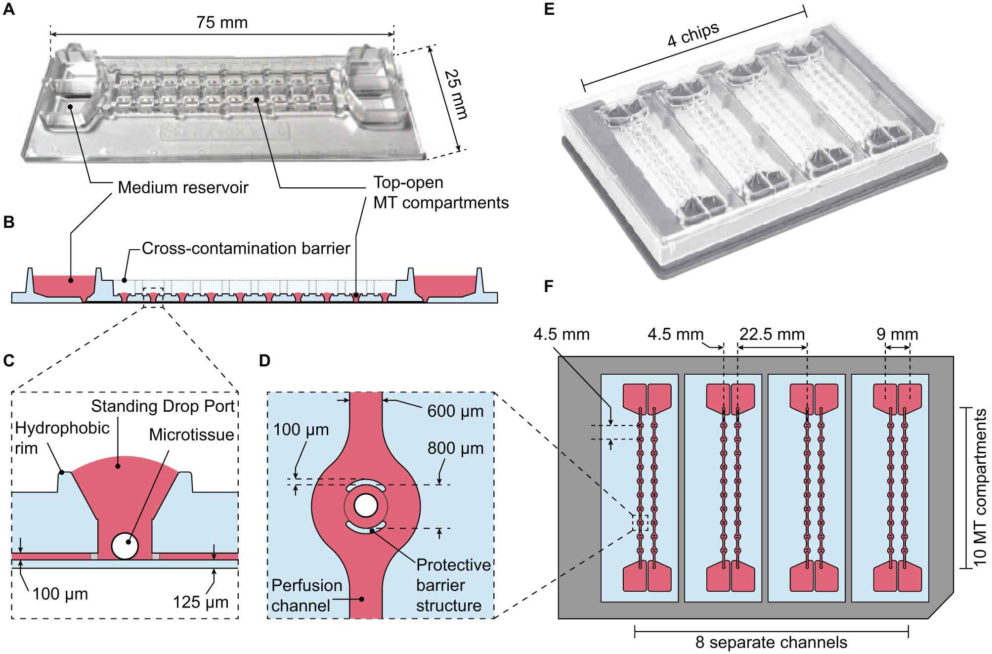
The microfluidic chip design builds on previously published microfluidic platforms that permit combined culturing of different MT types.16,17 Its footprint matches that of standard microscope slides (25 × 75 mm2), and the MT compartment pitch matches that of microtiter plates. The design is composed of two separate microfluidic channels, featuring 10 MT compartments each, and medium reservoirs at both ends of each channel ( Fig. 1A,B ).
Layout of the microfluidic chip. (
The central feature of the chip is the MT compartment. It is designed as a cylinder with a funnel-like structure that opens to the top and is surrounded by a hydrophobic rim ( Fig. 1C ). Capillary pinning at the rim stabilizes standing drops that cap the MT compartment upon filling the chip with liquid. A wall was structured around each MT compartment opening and acts as a cross-contamination barrier between the two channels ( Fig. 1B ). The top-open design of the compartment has several advantages: (1) the funnel acts as a vent and prevents bubble formation during the initial filling process; (2) it enables direct access to the compartment for efficient loading of MTs into the chip, MT manipulation during experiments, or removal of MTs for downstream analysis; (3) no compartment closure is needed that may be tedious to realize, will render the device prone to bubble inclusion, and will interfere with the MT and the fluidic system (pump effect due to closure pressing); (4) dead volume can be kept minimal; (5) gas exchange is ensured in proximity to the culturing site; and (6) optical transparency of the material enables high-quality optical readouts. Protective barrier structures, patterned perpendicularly to the perfusion channel, protect MTs against flow shear stress, while they allow for a constant exchange of medium around the spheroid ( Fig. 1D ). Microfluidic channels end in medium reservoirs that hold up to 200 μL of cell culture medium ( Fig. 1A ). All reservoirs are easily accessible for supernatant sampling and medium exchange throughout the experiments. Four chips can be assembled in a handling frame (Microfluidic ChipShop, Jena, Germany), resulting in a platform with Society for Biomolecular Sciences (SBS) standard formats (footprint dimensions of 128.8 mm × 85.5 mm and well spacing of 4.5 mm; Fig. 1E,F ).26,27 Thus, one assembled platform enables culturing of 8 ×10 MTs—of identical or different types—under eight identical or different conditions.
All MT compartments have a diameter of 800 μm, a height of 1.3 mm, and a volume of 1.04 μL, as shown in Figure 1 . The interconnecting perfusion channels are 600 μm wide, 100 μm high, and 52.4 mm long. A single channel and the respective 10 MT compartments have a combined volume of 16.5 μL, which remains in the chip during medium exchange. The dead volume in the funnel structure above the 10 MTs, which is not directly replaced by perfusion, has a volume of 1.02 μL (10.2 μL in total per channel). MT compartments are spaced in an SBS fashion to coincide with the positions of the wells of a 384-well microtiter plate (4.5 mm pitch). Medium reservoir positions match the wells of a 96-well plate (9 mm pitch). The top-open design of the MT compartments and the use of standard formats enable the use of common multichannel pipettes and enable automated chip and frame operation.
The chips were produced by injection molding of PS, and the channels were sealed with a 125 μm thick PS membrane ( Fig. 1C ). Microfluidic chips with a long-term stable hydrophilic and cell-repellent surface coating in the channels, compartments, and reservoirs are commercially available from InSphero AG (Schlieren, Switzerland).
Chip Loading and Operation
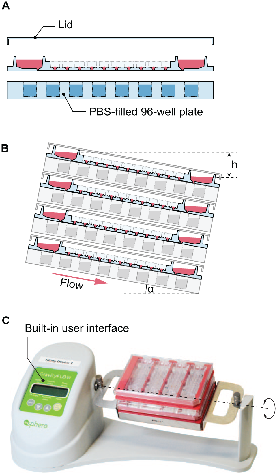
Chips are single use and provided in a sterile state. To fill channels with cell culture medium, the assembled plate with four chips is tilted along its long axis, and medium (37 °C) is filled into the upper reservoir. The height difference between the two reservoirs drives the flow through the channel to the lower reservoir ( Fig. 2B ).
Operation of the microfluidic device. (
The plate is then placed in a horizontal position for MT loading. Previously formed MTs are aspired from microtiter plates and are loaded into the MT compartments by contact transfer via the standing drop ports (see below). MT loading can be performed (1) individually with a single-channel pipette, (2) in parallel with multichannel pipettes for up to 96 channels, or (3) automatically with a robotic liquid handling system. The medium is fully exchanged after loading to compensate for medium evaporation during the MT loading procedure. The loaded plate is covered with a lid (Microfluidic ChipShop) fitting the handling frame ( Fig. 2A ).
To minimize medium evaporation during the experiment, three measures were applied: (1) All MT compartments were sealed with an adhesive, custom-cut polyester film with holes for oxygen exchange, sticking to the aforementioned cross-contamination barrier. (2) The reservoirs were sealed with a custom-cut, pressure-sensitive film with holes that provide access to the reservoirs for sampling of supernatant and medium exchange. (3) The plate was stacked onto a phosphate-buffered saline (PBS)-filled 96-well microtiter plate to increase water saturation of the air in direct proximity to the chips ( Fig. 2A ).
Channel perfusion is gravity driven. Tilting of the assembled plate around its long axis results in a height difference between the two reservoirs connected to each channel. The hydrostatic pressure difference between the reservoirs then pushes medium from the upper to the lower reservoir through the channels. Upon tilting the plate back and forth, medium is shuffled continuously between the two reservoirs. Capillary forces at the reservoir–channel junction retain liquid in the channels in the event that the upper reservoir would dry out. This effect prevents complete drainage of the channel, which would lead to (1) introduction of bubbles into the channel or (2) drying out of the MTs. The assembled and loaded plate was operated on a programmable tilting stage (InSphero AG). The stage allows for adjustment of the positive and negative tilting angle, resting times at tilted or horizontal positions, and transition times between positive and negative angles. The entire setup ( Fig. 2C ) fits into a standard benchtop cell culture incubator, where experiments can be performed in a controlled environment over several days. The microfluidic plate can be handled like a conventional microtiter plate for sampling of supernatant, medium exchange, and imaging. A short interruption of the tilting and removal of the plates from the incubator is required for any of these activities. For parallelization of experiments, up to four plates can be stacked onto each other on the same tilting stage, which yields 32 different experimental conditions with up to 320 MTs. Further parallelization can be achieved by increasing the number of tilting stages in the same incubator. All handling and operation steps can be performed under sterile conditions.
Flow Rate Measurements
Measuring the flow rate in the chip at various tilting angles was achieved by setting an assembled platform on a tilting stage at a defined angle
The previously determined volume
Computational Modeling
The purpose of operating the chip at defined tilting angles is to ensure continuous perfusion throughout the experiment. Numerical models of gravity-driven flow and capillary effects provide insights on the operational limits of the chip to avoid drying out reservoirs or inducing leakage at the standing drop ports. Since flow rates at 37 °C could not be measured, a model, based on previous analytical techniques,28,29 was developed to calculate flow rates, which was validated with 20 °C flow rate measurements at various time points (see Fig. 5A–C ). The model included the combination of a matrix implementation of the hydraulic-electric analogy with Kirchhoff’s law and time-stepping with the forward Euler method to establish a transient flow rate through all components of the chip. More detailed information can be found in the Supplemental Methods to this article.
Absorption Experiments
Two different chip materials—PDMS and PS—were compared with regard to their absorption characteristics of different molecules. PDMS chips were fabricated according to previously published techniques. 17 PDMS chips and PS chips were filled with 150 μL of cell culture medium containing biologically—for in vitro experiments—relevant concentrations of one substance per condition: diazepam (1 μM), acetaminophen (5 mM), testosterone (4.5 μM) (all obtained from Sigma-Aldrich, Buchs, Switzerland), and albumin (5 μg mL−1; Bethyl Laboratories Inc., Montgomery, TX). The filled microfluidic chips were placed in an incubator and were operated by tilting for the duration of the experiment. Medium (5 μL) was sampled out of the reservoirs at several time points between 0 and 48 h to track molecule concentrations in the channels. No fresh medium was added at these time points. Diazepam, testosterone, and acetaminophen were externally quantified by ultra-performance liquid chromatography–mass spectrometry (UPLC-MS; Admescope Oy, Oulu, Finland). Albumin concentrations were measured using an enzyme-linked immunosorbent assay (ELISA) as described later.
Nile Red (Sigma-Aldrich) and Cy3-coupled antibody (Cy3 AffiniPure Donkey Anti-Chicken IgY, Jackson ImmunoResearch Europe Ltd., Cambridgeshire, UK) concentrations were monitored by fluorescence microscopy (λEx 565 nm/λEm 610/75 nm) over 24 h.
Oxygen Measurements
The 2D oxygen distribution in the channel and MT compartments was measured over time to assess oxygenation via the standing drop ports. An oxygen sensor foil (PreSens Precision Sensing GmbH, Regensburg, Germany) was used to close the channels of the chip at the bottom. Cell culture medium was loaded into the chip, and the chip was placed into a chamber with constant nitrogen perfusion to deplete the medium of oxygen. After 20 min, one of the channels was sealed with a polyester foil, and nitrogen perfusion was turned off. To limit oxygen distribution only to diffusion from medium reservoirs or the standing drop ports, the chips were maintained without tilting. The oxygen-dependent fluorescence signal of the sensor foil was tracked by taking images every 15 s during 20 min using the VisiSens TD detector (PreSens). The relative oxygen concentration within the channels was calculated in reference to oxygen-depleted medium containing sodium sulfite (Na2SO3; Sigma-Aldrich) and medium equilibrated with ambient air. The data were evaluated using VisiSens ScientifiCal Software (PreSens).
Cell Culture
All spheroids used for experiments were produced off chip and were then transferred into the MT compartments of the chip. Human liver microtissues (hLiMTs) were obtained from InSphero AG and delivered ready to use in Akura 96-MT plates (InSphero AG). They were maintained in human liver maintenance medium AF (hLiMM-AF; InSphero AG), and medium was exchanged every 2–3 days until MT transfer and usage on the chip system.
Tumor microtissues (TuMTs) were formed using the HCT116 human colon carcinoma cell line or the green fluorescent protein (GFP)-tagged MDA-MB-361 breast adenocarcinoma cell line, both provided by InSphero AG. Three hundred cells in 70 μL of cell culture medium were seeded into each well of Akura 96-MT plates and spun down at 250g for 2 min. To accumulate cells in one corner of the well and enhance spheroid formation, the plate was placed in a cell culture incubator in a slightly tilted position. After 3 days of formation, spheroids with a diameter of 250 μm could be transferred into the microfluidic chip. RPMI-1640 medium (Gibco, Fisher Scientific, Illkirch Cedex, France), supplemented with 10% fetal bovine serum (FBS; Sigma-Aldrich) and 1% penicillin and streptomycin, was used for TuMT formation and maintenance.
For on-chip MT culture, assembled and loaded plates were tilted by 20° with tilting intervals of 7 min and transition times of 50 s. Co-culture experiments combining both spheroid types were performed using hLiMM-AF as common medium.
Biochemical Assays
Urea, a biomarker for liver functionality, was quantified in the cell culture supernatant using the QuantiChrom Urea Assay Kit (BioAssay Systems, Hayward, CA) according to the manufacturer’s protocol. The viability of all spheroids was assessed at the end of experiments measuring intracellular adenosine triphosphate (ATP) with the CellTiter-Glo 3D Cell Viability Assay (Promega AG, Dübendorf, Switzerland). To this end, spheroids were harvested from chip and transferred back into Akura 96 MT plates before performing the assay according to the manufacturer’s guidelines. Human albumin was quantified using ELISA (Bethyl Laboratories Inc., Montgomery, TX) according to the manufacturer’s protocol.
Imaging
Bright-field and fluorescence images were acquired using an inverted microscope (DMI-6000B; Leica Microsystems AG, Heerbrugg, Switzerland) with a 5× objective, a CCD camera (DFC-340-FX; Leica), and a stage top incubator enabling long-term life imaging. To focus on the elevated microfluidic chips in the handling frame, a distance ring (Thorlabs GmbH, Dachau, Germany) was used to increase the parfocal length of the objective. All images were analyzed using ImageJ software.
High-resolution images were recorded on an Olympus FV-MPERS system, equipped with a Newport SpectraPhysics DS+ two-photon laser. A XLPLN25XSVMP (25×, NA 1.0) water-immersed lens was used for imaging. The excitation wavelength was set to 900 nm. The spatial resolution was 0.63 × 0.63 × 2 µm3. A total of 119 images were acquired along the z direction to cover the entire spheroid.
Results and Discussion
Material Properties
A major improvement from previous prototypes is the complete replacement of PDMS. Since the chip does not feature any on-chip valves and pumps, no elastic material (i.e., PDMS) was needed, and PS could be used. PS is a validated material for cell culture applications and features a range of favorable advantages over PDMS.
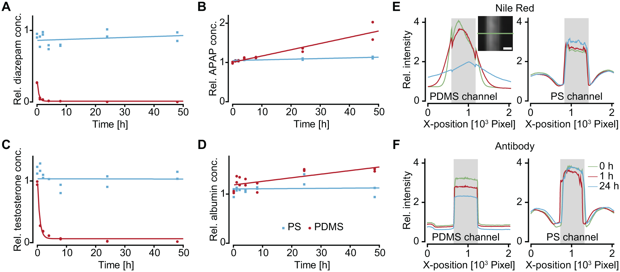
Part of this study focuses on comparing absorption of biologically relevant substances in PDMS and PS by tracking their concentration over time. To highlight substance–material interaction, hydrophobic and hydrophilic molecules were chosen from three classes: (1) drug compounds, delivered to the cellular model, for example, diazepam (hydrophobic) and acetaminophen (hydrophilic), which are commonly used compounds to gain insights into transcellular permeability and liver toxicity; (2) hormones and proteins, secreted by cells to communicate with other cell types, serving as viability, functionality, or responsiveness readouts, for example, testosterone (hydrophobic) and albumin (hydrophilic), which are molecules, secreted by Leydig cells and liver; and (3) on-chip staining compounds serving as labels for fluorescence imaging, for example, Nile Red (hydrophobic) and Cy3-coupled antibodies (hydrophilic). The fluorescent compounds were chosen to demonstrate material-dependent staining efficiency and imaging quality on chip. All measured compound concentration values were normalized to the initial concentration before loading.
The selected drug compounds show different material-dependent concentration changes. The hydrophobic diazepam ( Fig. 3A ) remained at a constant concentration within the PS chip, whereas its concentration drastically decreased in the PDMS chip. Already after 4 h, only 5% of the initial concentration was present in the PDMS channel. Concentrations of the hydrophilic acetaminophen ( Fig. 3B ), on the other hand, did not decrease in channels of both materials. Whereas the acetaminophen concentration remained constant in the PS chip, its concentration increased in the PDMS chip. The hydrophobic testosterone showed similar characteristics as diazepam: its concentration in PDMS channels rapidly decreased over the course of the experiment and, after 4 h, only about 10% of the initial concentration in the solution was detectable. The concentrations of the large, hydrophilic molecule albumin did not change much in both materials. Again, a slight increase was observed in PDMS channels. The observation of increased concentrations in PDMS can be explained by evaporation of water through the porous polymer material, 30 which is not the case for using PS. Fluctuations of compound concentrations in the PS chip can be explained by the manual sampling of a liquid volume of 5 μL and the subsequent two dilution steps to then conduct the analysis, as small inaccuracies in sampling volume potentiate upon dilution. Furthermore, unequal evaporation in the two technical replicates may have introduced experimental errors.
Absorption of substances in PDMS and PS. (
The distribution of Nile Red and Cy3-coupled antibodies was monitored by fluorescence microscopy. The microfluidic channel was imaged at three time points: directly after loading, after 1 h, and after 24 h. Bright-field images indicate the outline of the respective channels, and fluorescence images ( Suppl. Fig. S1 ) show the distribution of substances across the chips. The fluorescence signal intensity was analyzed along a cross section orthogonally to the channel. Nile Red is a small hydrophobic dye that is used to stain lipids. It showed fast leakage into the PDMS material directly after loading of the chip ( Fig. 3E ). During incubation time, the corresponding fluorescence signal within the channel region steadily decreased and reached approximately 40% after 24 h, while Nile Red penetrated deeper into the material and spread away from the channel. The intensity profile along the channel cross section illustrates this shift of fluorescence intensity over time. In the channels of the PS chips ( Fig. 3E ), on the other hand, the fluorescence signal remained localized inside the channel structure with clear drops in the intensity profile that coincided with channel walls. No decrease of fluorescence intensity within the channel regions was observed. The fluorescence signal of Cy3-labeled antibodies inside the channel structures did not change for both PDMS and PS chips ( Fig. 3F ). The clear edges at the channel borders indicated that there was no diffusion of the molecule into the chip material. A difference that was observed between the two chip materials included a decreasing signal over time in the PDMS chip. The signal reduction in the PDMS chip might be a result of unspecific adsorption in MT compartments and reservoirs.
Comparing the chips made from two different materials, we found that several substances were absorbed or adsorbed in PDMS, whereas their concentrations did not change in PS. The absorption of substances into PDMS depended mainly on their molecular size and hydrophobicity and could be estimated to a certain degree. Precise concentration control cannot be guaranteed in a PDMS-based microfluidic system, in particular with advanced experimental protocols including repeated compound dosing and extended exposure times. Our results therefore demonstrate a clear advantage of PS over the commonly used PDMS as a microfluidic chip material.
Operation by Tilting
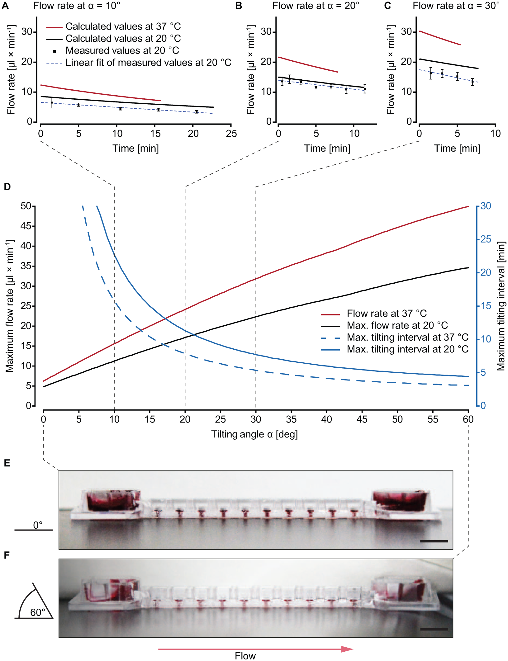
Control of the flow rate is crucial to reliably operate microfluidic MT culture chips. Here, flow was driven by reservoir height differences and channel parameters, that is, through gravity and hydraulic resistance. Flow rates at tilting angles of 10°, 20°, and 30° were modeled numerically until complete drainage of the upper reservoir into the lower one was achieved. Measurements were performed for the same tilting angles over defined time intervals. Thus, the graphs of both calculated and measured flow rates end at the time point when the respective upper reservoirs fell dry ( Fig. 4A–C ).
Tilting angle-dependent perfusion of the chip using an initial liquid volume of 150 μL. (
Numerical Model
Medium flow through the channels and into the standing drops was determined for various temperatures
The hydraulic-electric analogy was used to determine the flow rate over time at various tilting angles with the following components: (1) a hydraulic resistance
Experimental Measurements
The measured values were compared with predicted values obtained by computational modeling ( Fig. 4A–C ). The flow rates decreased over time, due to drainage of the upper reservoir and filling of the lower reservoir, resulting in a decreasing gravity-induced hydrostatic pressure. The slope of the measured flow rates correlated with that of the calculated ones ( Suppl. Fig. S2 ), the values being generally slightly lower. The slopes of the decreasing flow rates over time at 20 °C amounted to −0.16 ± 0.018, −0.30 ± 0.037, and −0.54 ± 0.105 μL min−2 for the measured values and −0.16 ± 0.001, −0.30 ± 0.001, and −0.41 ± 0.001 μL min−2 for the modeled values at tilting angles of 10°, 20°, and 30°, respectively. The discrepancy between computational models and experimental results can be explained by several effects: (1) the density and viscosity of the cell culture medium differs slightly from that of water, especially when using FBS-supplemented medium; 31 (2) the PS chip shrunk by a couple of micrometers during the fabrication process, decreasing channel dimensions, which entailed increased channel hydraulic resistance and lower flow rates; (3) capillary wetting effects in the reservoirs reduce the effective hydrostatic pressure, leading to decreased flow rates, especially at larger tilting angles; and (4) modeling of the distribution of incoming liquid in the lower reservoir becomes challenging with increasing tilting angles. Nevertheless, the correlation between the measured values and the computational models at 10° and 20° shows that flow rate and tilting time at different angles can be approximated. The same computational model was then used to extrapolate flow rates for MT culture conditions (37 °C) in Figure 4A–D . Compared with room temperature, culture conditions decrease the viscosity and density of liquids. This decrease has a multiplicative effect on the flow rate, which leads to proportionally higher flow rates, that is, less time before drainage of the upper reservoir at culture conditions.
Figure 4D summarizes the effect of the tilting angle at 20 and 37 °C on the maximum flow rate and maximum tilting interval with an initial medium volume of 150 μL (maximum flow rate value and maximum time, respectively, in Fig. 4A–C ). Exceeding the maximum tilting interval results in an interruption of the flow through the chip. Since continuous perfusion should be maintained throughout the experiment, interval time must be carefully considered when programming the tilting scheme. Furthermore, the viscosity of the cell culture medium changes with its contents. FBS-supplemented medium or flowing cells can therefore also influence the flow rate in the chip. 31 The range of applicable flow rates in the chip is only limited by the stability of the standing drops and the risk that the standing drop will burst—that is, liquid flows out of the standing drops—due to excessive hydrostatic pressure at large tilting angles. Monitoring the drops from the side while steadily increasing the tilting angle shows that angles of up to 60° do not result in standing drop bursting ( Fig. 4E,F ). Variations in the initially loaded liquid volume also affect resulting flow rates and applicable tilting intervals, as shown in Supplemental Figure S3 . The bidirectional flow upon repeated tilting is shown in Supplemental Figure S4 .
The ability to conveniently define the operation conditions (e.g., the flow rate) by controlling the tilting angle of the device, and the large range of applicable tilting angles render the developed chip system flexible and straightforward to use. In addition, the obtained flow rates are in good agreement with computational model guided values to ensure molecule concentration uniformity within MPSs. 32
Standing Drop Port and MT Compartment
The key features of the chip are the standing drop ports and MT compartments. The top-open MT compartments, spaced in compliance with SBS standard formats, enable the usage of a wide range of standard pipetting equipment—from manual/automatic single-/multichannel pipettes to fully automated liquid handling robots—to load MTs into the chip. Figure 5A shows a schematic of the MT transfer from their production plates into the chip system using five channels of an eight-channel multichannel pipette or a robotic pipetting system. Several spheroids are taken up from microtiter plates in parallel—one per pipette tip—by aspirating 3–10 μL of cell culture medium. Upon sedimentation of the MT to the opening of the pipette tip, these are transferred into the standing drop port by contact transfer. Touching the drop with the pipette tip lets the spheroid settle through the standing drop liquid interface and—guided by the funnel structure—down into the designated MT compartment. No pumping action is required, which minimizes liquid carryover. This transfer method also entails a minimum of potentially damaging fluid shear stress, as each MT is subjected to only one pipetting step and as neighboring MT compartments are not disturbed upon pipetting into a target compartment.
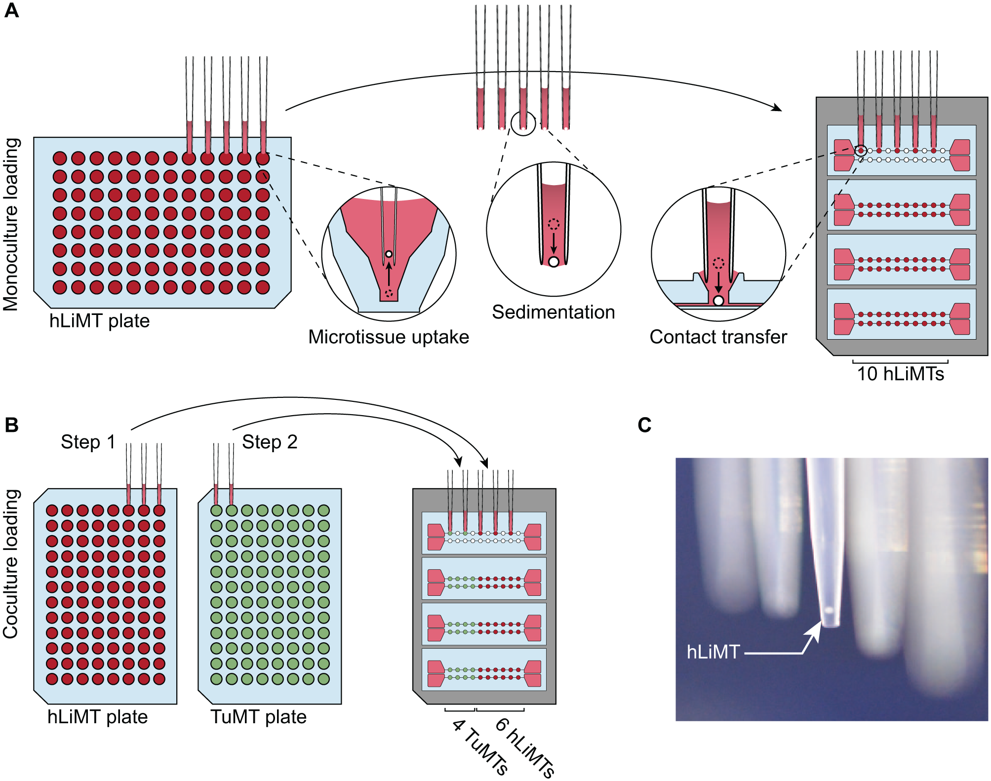
Schematic of the MT loading procedure with an eight-channel pipette or an automated pipetting system. Spheroids are picked up in parallel from production plates and sediment to the opening of the pipette tips. Approaching the standing drop port with the pipette tip, the two liquids combine, and the MT is transferred into the compartment. (
Chip MT Loading
Figure 5 illustrates that the number of simultaneously transferred MTs depends on the operation mode, that is, the use of mono- or co-culture scenarios on the chip. For a monoculture configuration, we used a 9 mm pitch multichannel pipette, which enables a transfer of five MTs per pipetting step—requiring two pipetting steps per microfluidic channel ( Fig. 5A ). Since different MT types are received on separate microtiter plates, the use of a co-culture configuration entails a transfer of one to five MTs per pipetting step, which requires up to 10 pipetting steps in total for a completely heterogeneous configuration. Figure 5B illustrates the pipetting scheme for a co-culture configuration of four TuMTs and six hLiMTs. The use of externally fabricated MTs offers several advantages, for example, the robustness of the procedure and the possibility to introduce quality control steps, but it also requires an efficient loading method. Table 1 compares characteristic parameters for chip loading procedures for single- and multitissue configurations. We distinguished between the overall loading time, that is, the time for the entire loading procedure, and the bench time, that is, the time needed for active user manipulations. The transfer efficacy was used as a measure of how many MTs were successfully transferred to their target locations. Empty MT compartments were afterwards manually populated. Transfer with a manual single-channel pipette required the largest amount of bench time, with 20 pipetting steps per chip, but offered a high degree of control over the process, leading to a high transfer efficacy. By using an electronic eight-channel pipette with 9 mm pitch, the loading throughput could be increased, with four to eight pipetting steps per chip, but the loading efficacy was lowered, since pipetting five MTs simultaneously required precise tip placement, which was tedious when manually performed. Ninety-six-channel semiautomated pipetting systems (VIAFLO 96/384, Integra Biosciences, Zizers, Switzerland) offered guided tip positioning and loading of all four chips in parallel ( Suppl. Movie S1 ). The loading time could therefore be further reduced, while loading efficiency was still high. Transfer with a fully automated liquid handling robot (Hamilton STAR, Hamilton Bonaduz AG, Bonaduz, Switzerland), equipped with eight pipetting channels, enabled us to use the same pipetting patterns as with the eight-channel pipette, that is, the transfer of two to five MTs simultaneously and a filling of the chip in four to eight pipetting steps ( Suppl. Movie S2 ). In contrast to the other loading methods, the loading time here markedly differed from the actual bench time. User manipulation was reduced to setting up the liquid handling robot with corresponding microtiter plates and empty chips. After robot initiation, all MTs were transferred to their designated MT compartment autonomously. The transfer efficiency between two 96-well plates reached 100%, without any damage to the MTs, by adapting the liquid handling robots’ pipetting speed and volume for MT pickup ( Suppl. Fig. S5 ).
Characteristic Parameters for Chip Loading Using Different Pipetting Equipment.
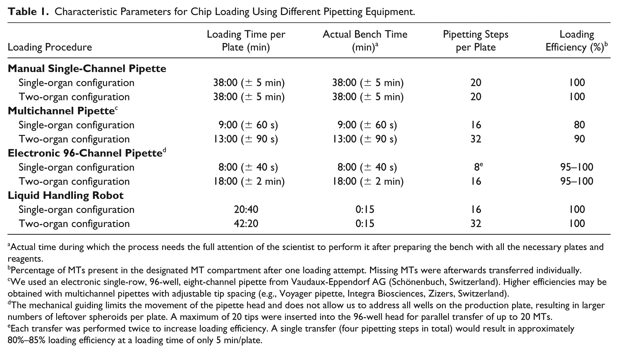
Actual time during which the process needs the full attention of the scientist to perform it after preparing the bench with all the necessary plates and reagents.
Percentage of MTs present in the designated MT compartment after one loading attempt. Missing MTs were afterwards transferred individually.
We used an electronic single-row, 96-well, eight-channel pipette from Vaudaux-Eppendorf AG (Schönenbuch, Switzerland). Higher efficiencies may be obtained with multichannel pipettes with adjustable tip spacing (e.g., Voyager pipette, Integra Biosciences, Zizers, Switzerland).
The mechanical guiding limits the movement of the pipette head and does not allow us to address all wells on the production plate, resulting in larger numbers of leftover spheroids per plate. A maximum of 20 tips were inserted into the 96-well head for parallel transfer of up to 20 MTs.
Each transfer was performed twice to increase loading efficiency. A single transfer (four pipetting steps in total) would result in approximately 80%–85% loading efficiency at a loading time of only 5 min/plate.
Chip MT Harvesting
The same procedures as used for loading can be applied to harvest MTs for off-chip analyses at the end of an experiment. Each MT can be individually targeted and analyzed, which expands the readout options for a single experiment. To remove MTs, pipette tips were positioned at the standing drop ports, and the MTs were taken up with 3–5 μL of medium ( Fig. 6A ). They were then transferred into microtiter plates, where they could be individually processed. For example, the viability of individual MTs could be determined by MT lysis and quantification of intracellular ATP concentrations. At the same time, remaining MTs of the same experiment and channel could be fixed and stained individually. Routinely applied methods for static MT cultures can be used. Especially for multitissue configurations, it is crucial to separate the respective organ MTs and perform tissue-specific readouts.
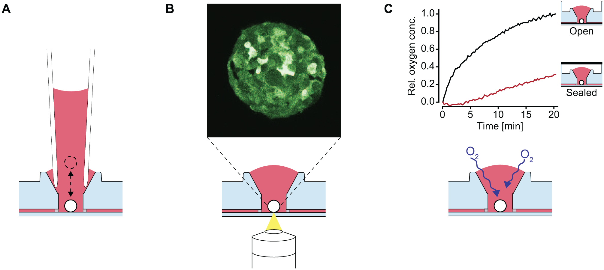
Advantages of the standing drop port. (
MT Monitoring
The top-open design and the 125 μm thin PS membrane at the bottom of the MT compartments render the chip compatible with high-resolution imaging. Figure 6B and Supplemental Movie S3 show a slice through and the full stack of an MT consisting of GFP-tagged MDA-MB-361 breast adenocarcinoma cells. The on-chip live image was taken with an inverted multiphoton microscope and demonstrates the suitability of the chip for use with high-resolution imaging techniques. The 125 μm distance in between the objective and the MT enables the use of high-NA-immersion objectives.
MT Oxygen Supply
A further advantage of the top-open design of the MT compartment is the increased surface area of the medium and its exposure to air. PS, in contrast to PDMS, is not permeable to gas. This property can lead to oxygen limitations at the cell or MT culture sites in closed microfluidic systems.
To assess oxygenation of the medium at the MT culturing sites, the medium in the chip was depleted of oxygen and its recovery was monitored over 20 min. The oxygenation was compared with a separate, hermetically sealed channel, simulating a closed microfluidic environment. The oxygen concentration in the open channel quickly increased upon exposure to ambient air ( Fig. 6C ), approaching equilibrium within approximately 20 min. In contrast, the oxygenation in the closed channel was substantially delayed. An increase of dissolved oxygen was only observed after 5 min, and the concentration reached approximately 30% after 20 min. The delayed increase of oxygen within the closed channel can be explained by the fact that diffusion of oxygen can only occur through the open medium reservoirs at the ends of the channel.
In combination with the open reservoirs at the ends of the channels, the open standing drop ports improve the culture conditions for cell types that are sensitive to low oxygen levels ( Fig. 6C ).
On-Chip Microtissue Culture
Two different spheroid types, hLiMTs and TuMTs, were co-cultured over 7 days. Several identical (monoculture) or different (co-culture) spheroids were interconnected under conditions of constant perfusion on a chip, and their characteristics were compared with those of spheroids cultured under static conditions in a 96-well microtiter plate—one MT per well, that is, no interconnections. For monoculture experiments on chip, 6 hLiMTs, 10 hLiMTs, or 10 TuMTs were cultured in the same channel. Co-culture configurations included six hLiMTs and four TuMTs in one channel ( Fig. 7A ). Spheroid imaging, sampling of the supernatant, and medium exchange were performed on days 0, 2, 4, and 7 for all culture conditions. On day 7, the spheroids were harvested, and intracellular ATP concentrations were measured to assess their viability.
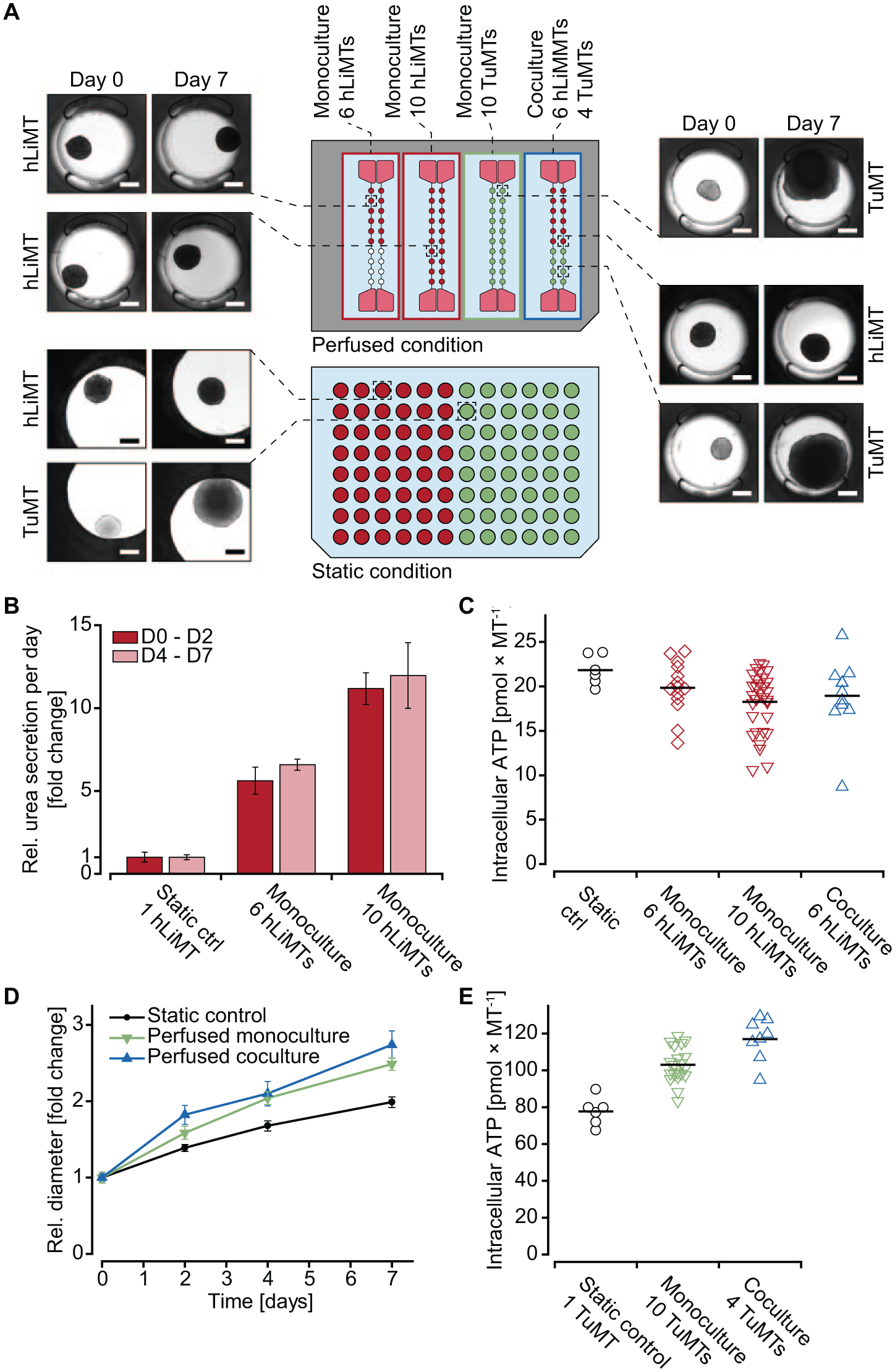
Culturing of hLiMTs (red) and TuMTs (green) in mono- and co-culture (blue) configurations on chip and under static conditions in well microtiter plates. (
Images of spheroids were taken to observe potential morphological changes, which may indicate harmful effects of the perfusion conditions. Liver MTs ( Fig. 7A ) showed similar morphology for all different culturing conditions and for all time points. Sizes and shapes of the spheroids were similar under static and perfusion culturing conditions and did not change over the duration of the experiment. To assess the functionality of hLiMTs, urea was quantified in the freshly sampled supernatant on days 2 and 7. Urea is a waste product of the human body, used for ammonia detoxification, and is primarily synthesized by the liver. Quantification of the molecule in cell culture supernatants is used as an indicator for the metabolic activity of cells. The amount of urea produced by one spheroid under static conditions was compared with that produced by 6 or 10 spheroids in the same channel under perfusion ( Fig. 7B ). Measured values showed an enrichment of urea in the supernatant, proportional to the number of hLiMTs in the system: in channels with 6 and 10 hLiMTs, the amount of measured urea was approximately 6- and 10-fold higher than that in a single-MT well under static conditions with secretion rates of 82.0–97.8 ng MT−1 day−1 on day 2 and 44.0–52.6 ng MT−1 day−1 on day 7. Lower urea secretion rates on day 7 can be explained by decreasing secretion rates of the cellular model over time, which has been described previously for different primary hepatocyte models.33,34 Consistent tissue number-dependent amounts of urea on both days, however, demonstrated that there were no negative effects of the culturing of hLiMTs in the microfluidic chips. Measurements of intracellular ATP concentrations on the last day of the experiment ( Fig. 7C ) revealed that hLiMTs, cultured under static conditions or in perfused monoculture or co-culture configurations, all remained similarly viable. The size of hLiMTs remained stable over time under all conditions, which was expected based on their nonproliferative nature ( Suppl. Fig. S6 ). Further, the reproducibility of these experimental results could be shown by culturing up to 80 hLiMTs over 7–14 days independently in two different labs with different persons operating the chip system. Chips with 10 hLiMTs per channel were maintained for 14 days. The MT size was tracked over the experimental period, and intracellular ATP was measured on days 7 and 14. The results were in good agreement with other independently conducted experiments and demonstrated the robustness and reproducibility of the microfluidic MT culture chip ( Suppl. Fig. S7 ).
Also, the tumor model was cultured as single spheroids in static 96-well microtiter plates and under perfusion in mono- and co-culture configurations with hLiMTs. On day 0, all TuMTs were similar in size (approximately 210–250 µm) and morphology ( Fig. 7A ) for the three different culture conditions. On day 7, the TuMTs had grown considerably (approximately 480–610 µm), nearly overgrowing the MT compartments in some cases. TuMT growth was tracked by measuring their diameter on days 0, 2, 4, and 7 ( Fig. 7D ). Uniform growth was seen for all spheroids cultured under perfusion (approximately 50 μm day−1 in diameter), while static conditions led to a considerably lower growth rate (approximately 35 μm day−1). These observations can be explained by the fact that perfusion entails a constant delivery of nutrients to the MT compartments, whereas static culturing conditions are diffusion limited within the culture well volume. Standard deviations of TuMT growth were remarkably low, indicating a high uniformity among TuMTs for the same condition, within the same or different channels. These observations were represented as ATP contents of TuMTs on day 7 ( Fig. 7E ), which were lower in the smaller spheroids cultured under static conditions in well plates compared with perfusion conditions. However, TuMTs showed similar ATP/cell mass ratios for all conditions with 148.7 ± 16.1 pmol mm−3 for monoculture perfusion, 144.8 ± 29.1 pmol mm−3 for co-culture perfusion, and 147.5 ± 16.6 pmol mm−3 for static conditions.
Up to 10 hLiMTs were cultured in a volume of 150 μL without observing any negative impacts on their morphology, functionality, or viability. Furthermore, urea secretion by hLiMTs indicated that other metabolites or cytokines could also be enriched in the device between two medium exchanges as a result of the higher cell-to-medium ratio. Such up-concentration can be advantageous for readouts that are not feasible in standard microtiter plates. Single spheroids in the comparably large medium volumes of 96-well microtiter plates may not produce enough of certain biomarkers to exceed the respective lower limit of detection. Additionally, this up-concentration effect may also have advantages when combining different spheroids, since the concentrations of cytokines and metabolites produced by one tissue type are more likely to reach thresholds to act on the other target tissues.
By combining hLiMTs and TuMTs in the same channel, we showed that co-culture experiments are generally possible for at least 7 days. Noteworthy, combinations are not limited to these two spheroid types, but can be adapted as needed by the experimenter. Fine-tuning of medium formulations fitting the needs of all organ models, however, needs to be considered. Combinations of different spheroid types—or of spheroids with circulating cells, such as immune cells or circulating tumor cells—enable a range of studies, in which tissue communications and interaction play a major role. Combinations of liver models with other organs of choice, for example, are interesting for drug toxicity and efficacy screenings. Since the liver is the first organ to experience drugs that enter the human body, it is the main organ of first-pass metabolism, but also the primary victim of drug-induced toxicity. The liver therefore has a large influence on the concentration of drugs and their metabolites in the system and makes drug testing in combination with other target organs, such as the heart, brain, or pancreas, or tumors more representative and predictive. Other promising and feasible applications of the developed system could include (1) disease models involving inflammation, for example, inflammatory bowel disease, by combining an intestinal model with circulating cells of the immune system, or (2) models involving cancer progression by implementing circulating tumor cells and possible target MTs. The use of patient-derived cell material will be relevant in the field of personalized medicine.
Here, we presented a microfluidic chip system and its characterization, which holds great potential for large-scale integration in industrial applications. We demonstrated the advantages of using PS for chip production with respect to the absorption of metabolite or compound molecules over current academic devices made of PDMS.
Operation of the chip relies on gravity-driven flow and does not require specialized equipment, such as external tubing or expensive precision pumps. Nevertheless, flow rates could reliably be established and modulated, and a wide range of flow rates could be applied on demand.
A key feature of the chip was the newly designed MT compartment with its standing drop port. The top-open design was one of the pivotal features for application of the chip in high-throughput settings, since it allows for direct access to the MT culturing site with automated pipetting equipment. The versatility of using the microfluidic chip system with standard lab equipment to handle and load the chip with cellular models renders the chip system suitable for usage in different settings. Depending on the equipment available in the lab and the throughput needed, standard, low-cost solutions are as suitable to work with the device as are expensive, fully automated systems.
The performance of the microfluidic device in combination with the two cellular models, liver and cancer, demonstrates the flexibility of the system and the wide range of possible applications. A variety of different organ models in the form of MTs can be generated off chip with a high degree of reproducibility. External spheroid formation before loading and experimentation with the spheroids in the chip systems allows for introducing additional quality control steps to ensure optimal performance. MT numbers, combinations, and flow regimens can be modified on demand. The chip and its general operation remain the same, which allows us to standardize handling and operation to a large extent. Variations of the spheroid numbers in the system did not impact the functionality of individual spheroids, as was evidenced by the urea measurements. The presented features and the high flexibility in available tissue models render the presented chip system an ideal candidate for drug discovery and diagnostic applications.
Supplemental Material
Supplementary_Material_for_Microtissue_Culture_Chip_by_Lohasz_et_al_2018 – Supplemental material for Scalable Microfluidic Platform for Flexible Configuration of and Experiments with Microtissue Multiorgan Models
Supplemental material, Supplementary_Material_for_Microtissue_Culture_Chip_by_Lohasz_et_al_2018 for Scalable Microfluidic Platform for Flexible Configuration of and Experiments with Microtissue Multiorgan Models by Christian Lohasz, Nassim Rousset, Kasper Renggli, Andreas Hierlemann and Olivier Frey in SLAS Technology
Footnotes
Acknowledgements
The authors thank Martin Rausch, Novartis AG, for the high-resolution images taken for the study. We acknowledge David Fluri and Fabrizio Hürlimann for setting up MT transfer schemes with different pipetting equipment.
Declaration of Conflicting Interests
The authors disclosed the following potential conflicts of interest with respect to the research, authorship, and/or publication of this article: Olivier Frey is member of the management at InSphero AG, commercializing the microfluidic chip.
Funding
The authors disclosed receipt of the following financial support for the research, authorship, and/or publication of this article: The work was financially supported by Swiss CTI grant 18024.1 PFLS-LS.
Supplemental material is available online with this article.
References
Supplementary Material
Please find the following supplemental material available below.
For Open Access articles published under a Creative Commons License, all supplemental material carries the same license as the article it is associated with.
For non-Open Access articles published, all supplemental material carries a non-exclusive license, and permission requests for re-use of supplemental material or any part of supplemental material shall be sent directly to the copyright owner as specified in the copyright notice associated with the article.