
Abstract
The future of the life sciences is linked to automation and microfluidics. As robots start working side by side with scientists, robotic automation of microfluidics in general, and droplet microfluidics in particular, will significantly extend and accelerate the life sciences. Here, we demonstrate the automation of droplet microfluidics using an inexpensive liquid-handling robot to produce human scaffold-free cell spheroids at high throughput. We use pipette actuation and interface the pipetting tip with a droplet-generating microfluidic device. In this device, we produce highly monodisperse droplets with a diameter coefficient of variation (CV) lower than 2%. By encapsulating cells in these droplets, we produce cell spheroids in droplets and recover them to standard labware containers at a throughput of 85,000 spheroids per microfluidic circuit per hour. The viability of the cells in spheroids remains high throughout the process and decreases by >10% (depending on the cell line used) after a 16 h incubation period in nanoliter droplets and automated recovery. Scaffold-free cell spheroids and 3D tissue constructs recapitulate many aspects of functional human tissue more accurately than 2D or single-cell cultures, but assembly methods for spheroids (e.g., hanging drop microplates) have limited throughput. The increased throughput and decreased cost of our method enable spheroid production at the scale needed for lead discovery drug screening, and approach the cost at which these microtissues could be used as building blocks for organ-scale regenerative medicine.
Keywords
Introduction
We believe that the future of the life sciences is linked to automation and microfluidics. With robots working side by side with scientists, robotic automation of microfluidics in general, and droplet microfluidics in particular, will significantly extend and accelerate the life sciences.
Throughout the years, microfluidics has developed a plethora of applications, particularly in the life sciences, and has been part of miniaturizing, increasing throughput, and lowering the cost of a large number of macroscale sample processing and analysis techniques, as well as making possible new processes relying on microscale phenomena. Microfluidic technologies have seen some general automation approaches, such as pressure-controlled valving 1 and programmatically reconfigurable devices. 2 Most of these, however, require substantial infrastructure outside of the microfluidic device,3–7 and only very few (e.g., the Fluidigm integrated fluidic circuits) can be readily interfaced with general laboratory robotics such as liquid-handling robots.
One major microfluidic technology platform is droplet microfluidics. It is a high-throughput sample processing and analysis method enabled by miniaturizing the reaction vessels to nano- or picoliter droplets. 8 Droplet microfluidics relies on structured compartmentalization of immiscible liquids (e.g., water and fluorinated oil in the form of a water-in-oil emulsion stabilized by a surfactant).9,10 These tiny cell-scale compartments produced with high size accuracy allow for millions of individual biological events 11 or chemical reactions to take place simultaneously, 12 to a large extent chemically and physically separated. 13 A set of microfluidic devices is used in droplet microfluidics to form, merge, inject into, analyze, and sort millions of droplets quickly and efficiently. 8 Droplet microfluidics is used in multiple applications in biology, including metabolic pathway interaction studies, 14 single-cell genomics15,16 and transcriptomics, 17 digital droplet PCR, 18 directed microbial evolution, 19 as well as cell spheroid formation or cell aggregation in confined environments20,21 and cell encapsulation in gels. 22 Immense droplet production rates as high as 1 trillion(!) per hour have been achieved by parallelized droplet-generating devices containing up to 10.000 droplet generation nozzles.23,24
Automation of microfluidics in general and droplet microfluidics in particular is an obvious next step for technology development in this field. It is even more timely now, as more and more commercial applications are being developed based on droplet microfluidics. Automating even simple steps that are performed on a daily basis in droplet microfluidic workflows—such as droplet generation, as well as sample recovery/droplet breaking—is not a trivial task. For the automation to truly succeed, it has to rely on widely accessible, standardized solutions that are as simple as possible.
Liquid handling is an essential part of many experiments in the life sciences; therefore, large numbers of standardized solutions for liquid handling have been developed. These include the pipette and robotic pipetting workstations [also known as liquid-handling robots (LHRs)]. Robots can work without fatigue, increase throughput, perform consistently, and ensure accuracy and precision. 25 The pipetting robot has not previously been used as the sole automation tool to perform all the tasks needed for successful droplet generation or for droplet breaking and living content recovery. In this article, we present a fully automated workflow powered only by an LHR paired with a droplet microfluidic component. To demonstrate the approach, we use the LHR to automate the production of three-dimensional (3D) cell culture models, cell spheroids.
Uses for cell spheroids and other 3D tissue models are emerging areas of interest both in fundamental research and in industrial applications, because they provide more predictive in vitro models to study fundamental cell biology, disease pathophysiology, and the development of novel therapeutic agents.26,27 Spheroids are also considered a central component of regenerative medicine, being one of the key elements of the rapidly growing precision regenerative medicine field.28,29 As the demand for 3D cell culture models grows in the academic, medical, and industrial environments, there is an increasing need for affordable automation of spheroid production, because this process could eventually play a pivotal role in lowering the total expenses of spheroid fabrication and thus facilitating their use at a large scale. The increased throughput and decreased cost of our method enable spheroid production at the scale needed for lead discovery drug screening, and approach the price at which these microtissues could be used as building blocks for organ-scale regenerative medicine.
Materials and Methods
Droplet-Generating Microfluidic Chips
A droplet microfluidics circuit for production of nanoliter droplets was designed in AutoCAD (
Finally, the surface of all microchannels (made from PMMA and PSA tape) was treated with Aquapel. The surface-modifying chemical was removed from the channels by compressed nitrogen after 2 min. That step was followed by passing the hydrofluoroether (HFE) oil (Novec HFE-7500 Engineered Fluid; 3M, Two Harbors, MN) through all microchannels to wash out any remaining Aquapel. Finally, all the liquids were removed from the chip by compressed nitrogen.
To prevent sedimentation of the cells in the dispersed-phase/sample reservoir and clogging of the microfluidic microchannel, and to keep as much as possible equal numbers of cells entrapped in individual droplets, the whole droplet-generating chip was placed on a magnetic stirrer (IKA big squid; IKA, Staufen, Germany), and a sterile small magnet was placed in the dispersed-phase/cell-sample-containing reservoir. The magnetic stirrer was set at 150 rpm.
For collecting droplets, a modified 1 ml pipette tip was used (BRAND, 50–1000 µL; BrandTech, Essex, CT). A simple 4 mm latex sleeve [natural rubber latex tubing with outer diameter (OD) 2.3 mm and inner diameter (ID) 0.8 mm; Kent Elastomer Products, Inc., Kent, OH] was secured at the thinner end of the pipette tip. This rubber sleeve plays an important role, because it seals the connection between the output pipette tip being filled with generated droplets and the outlet of the droplet-generating chip.
Cell Sample
HEK293 cells were cultured in FreeStyle293 culture medium in a nonadhesive cell culture flask (125 mL Erlenmeyer flask, nonpyrogenic, polycarbonate; Corning, Corning, NY). RT4 and A-431 cells were cultured in McCoy’s 5A (Modified) Medium and RPMI culture medium, respectively, in a cell culture incubator (Heracell 150, 37 °C, 5% CO2; Thermo Scientific, Waltham, MA). Before encapsulating in droplets, the cell suspension was prepared to meet the desired concentration of cells (i.e., HEK cells: 3.88×10⁶, 4.7×10⁶, and 7×10⁶ cells/mL; RT4 cells: 4.52×10⁶ cells/mL; and A-431 cells: 7×10⁶ cells/mL).
Droplet Generation Process
As a continuous phase, an HFE (Novec HFE-7500 Engineered Fluid) with 1% polyethylene glycol–perfluoropolyether (PEG-PFPE) amphiphilic block copolymer surfactant (RainDance Technologies, Billerica, MA) was used. One milliliter of HFE with 1% of the surfactant was added to the continuous-phase reservoir with the aid of a pipetting robot (Opentrons OT-One-S Hood; Opentrons, Brooklyn, NY). This primes the microchannels, limiting to the minimum the amount of air trapped inside the network of microfluidic channels. The initial step was followed by filling up the dispersed-phase/sample reservoir with 500 µL of the cell suspension. Then, a negative pressure was applied to the upper end of the droplet-collecting element (a modified 1 ml pipette tip) by a computer-controlled pipette with which the LHR is equipped (DragonLAB TopPette 100–1000 µL; DragonLAB, Split, Croatia). The pipette was programmed to transfer 1000 µL in 100 steps (10 µL each), generating an estimated 0.58 kPa of negative pressure in each step at a frequency of 0.5 Hz. Once the suction force applies, it removes all the remaining air trapped in the system and starts the negative pressure–driven, micropipette-based droplet generation process.
Droplet Content Recovery
To recover the cells from within the droplets (i.e., to separate the continuous phase from the dispersed phase), a polytetrafluoroethylene (PTFE) filter membrane (PTFE filter, 0.45 µm pore size; Sartorius Biolab Products, Göttingen, Germany) was used. About 400 µL of the emulsion (containing ca. 17,000 droplets) was placed using a pipetting robot on the surface of the PTFE filter membrane. Immediately, the HFE oil drained into the membrane, destabilizing and breaking the emulsion and allowing the droplets to merge, forming a large droplet full of spheroids floating freely in the culture medium. Alternatively, a chemical-based sample recovery method was used, in which 400 µL of droplets were merged using 30 µL of perfluorooctanol.30,31 The recovered spheroids were subsequently analyzed for viability.
Cell Viability Test
HEK, RT4, and A-431 cell cultures
Before droplet generation, cell cultures were analyzed with a Bio-Rad TC20 Automated Cell Counter using Bio-Rad counting slides with dual chambers (cat. no. 145-0011; Bio-Rad, Hercules, CA). The cells were stained with Trypan Blue solution (cat. no. T8154-100ML; Sigma-Aldrich, St. Louis, MO), which selectively color dead cells blue. Live cells with intact cell membranes are not colored.
Ten microliters of the cell suspension were mixed with 10 µL of Trypan Blue, and finally 10 µL of the mixture was pipetted into one of the chambers of the counting slide. The automatic measurements were triplicated, and an average value of viable cells was calculated.
The viability of the used cells was 96% for HEK and A-431 cells, and 97% for RT4 cells.
Cell spheroids
To analyze the viability of the cells forming cell spheroids that were fabricated in droplets, a combination of Hoechst 3334 (cat. no. C47198; Life Technologies, Carlsbad, CA), propidium iodide (cat. no. C27858; Life Technologies), and Calcein AM green (cat. no. 56496-50UG; Sigma-Aldrich) was used. One microliter of each was added to 1000 µL of 1× phosphate-buffered saline (PBS). Then, 100 µL of the Hoechst 3334, propidium iodide, and Calcein AM mixture was added to a 50 µL solution containing the recovered spheroids (cell aggregates suspended in culture medium). This was followed by an incubation step of 30 min in the dark. Finally, fluorescent images of the stained spheroids were taken using fluorescent microscopy with a Nikon Eclipse Ti (Nikon, Tokyo, Japan) to measure the final viability of formed spheroids [in bright field, fluorescein isothiocyanate (FITC), tetramethylrhodamine (TRITC), and 4′,6-diamidino-2-phenylindole (DAPI)]. The number of dead cells was counted in a randomly selected image containing 40 spheroids. The viability of the cell spheroids (%) was calculated using the following formula: Number of dead cells / Estimated total number of cells forming a spheroid × 100.
Platform Setup
For the robot to operate smoothly, the device has to go through the initiation round. The operator has to make sure that the 1 mL pipette tip rack (
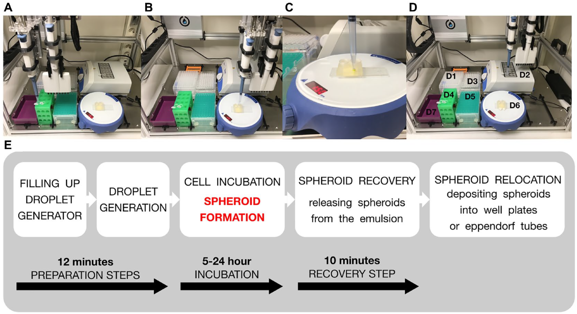
The automated workflow for generating cell spheroids using a robotized droplet microfluidic platform consists of five steps: (
Robot Operations
Setup
The robot’s head, equipped with a 1 mL pipettor, grabs a regular 1 mL pipette tip from the tip rack (
Droplet generation
From the A1 position of the 1 mL pipette tip rack (
(
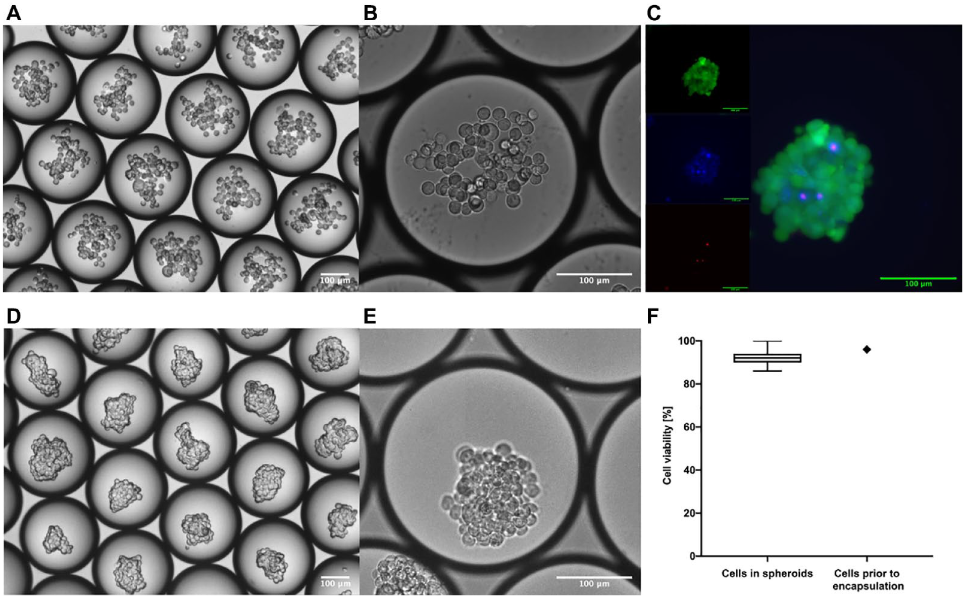
Images of HEK cells in droplets: (
After this step, the robot pauses for 300 s until a full 1 mL of liquid transfers through the network of the microchannels into a modified pipette tip. The pause in the workflow is needed for the pressure difference to equalize between the pipettor and the atmospheric pressure through the network of microchannels of the chip.33 The pause also limits sucking an excess amount of air into the droplet-containing pipette tip, which prevents the formation of a polydisperse emulsion.
Now, the tip attached to the pipettor doubles as a temporary droplet reservoir. Once all the droplets are collected, the robot lifts its pipettor and moves it above the heat block. The head is lowered, and the droplets are transferred into an Eppendorf tube, where the cells will be incubated for at least 16 h and will transform into spheroids. To prevent evaporation of droplets during the extended incubation, the emulsion is stored in Eppendorf tubes under a protective, immiscible, and nonvolatile layer formed by mineral oil (
Spheroid recovery
Once the overnight/16 h lasting pause is finished, the robot activates itself and grabs a clean tip from the 1 mL pipette tip rack (
Finally, the robot lifts its head a few millimeters up and removes 600 µL of the HFE oil that remains in the lower part of the tip, saving only the packed emulsion. Then, depending on the selected recovery method, the robot moves the pipettor either to the Eppendorf tube rack (
Results and Discussion
The robotically automated droplet microfluidic platform consists of four major components: a liquid-handling robot, a droplet-generating microfluidic chip, an interface connecting them, and a computer that controls every movement and action of the robot. The platform is built on a commercially available LHR. Opentrons OT-One Hood was chosen because of its open source, simple design, and relatively low price ($4000). The Opentrons OT-One Hood robot is essentially a standard 1 mL or eight-channel 300 µL pipettor attached to the robotic arm, which can move in all directions according to simple Python code. The LHR can be controlled either by a Python script or “manually” using a Python console and XYZ coordinates, as well as using Opentrons software—in all cases, an external computer with appropriate open-source software has to be connected to the robot.
Although the robot has 15 slots for the well plates on its deck, the design of the device allows accommodating only eight of them, meaning that only part of the surface of the deck (about 30×40 cm) can be used for fully automated operations. The rest of the surface is out of reach for both or just one of the pipettors attached to the robotic arm.
To fit the necessary equipment—a 1 mL tip rack, a waste box, a 12-slot Eppendorf tube rack, a 96-well plate, a full-size magnetic stirrer with a droplet-generating microfluidic chip on top of it, and a heat block for the Eppendorf tubes—we have used all of the eight available slots.
To generate relatively large quantities of highly monodisperse nanoliter droplets, a pressure source (negative32,35 or positive33,36) and a microfluidic chip based on specifically organized microchannels are needed.
37
To fulfill those requirements, we chose a simple flow-focusing design as the droplet-generating element, which we fabricated in a 2 mm thick PMMA plastic sheet using a CNC micromill.
38
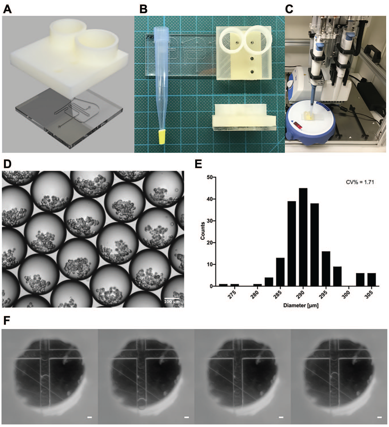
The CNC-engraved PMMA sheet was sealed with pressure-sensitive adhesive tape, forming a closed network of microfluidic channels. All microchannels, including the nozzle, were 200 µm wide and 100 µm deep (
To seamlessly connect a 1 mL pipette tip with the outlet of the microfluidic channel, we added a 4 mm long rubber O-ring at the lower part of the pipette tip. The conical shape of the 1 mL pipetting tip prevents the rubber O-ring from sliding along the tip and locks it in place. This modification allows the robot to use the same modified pipetting tip multiple times in a series of workflows (
The automated workflow for cell spheroid generation using the robotized droplet microfluidic platform consists of five steps: sample and reagent loading, droplet generation, cell incubation for spheroid formation, spheroid recovery, and spheroid dispensing. All steps are performed independently by the LHR without assistance from an operator. Throughout all steps, the LHR exactly follows the experimental protocol, which was uploaded as a Python script to the LHR-controlling computer. The LHR automatically transfers samples and generates, collects, and deposits droplets using the standard and modified pipette tips, respectively. Even though a regular 1 mL pipette operated by a robot was used as a negative pressure source, the measured size distribution of generated droplets [coefficient of variation (CV)%] was less than 2% (
Cell Incubation for Spheroid Formation
We have tested two methods for cell incubation. Cells in droplets were incubated either in an external incubator or on the heat block in an Eppendorf tube, where the HFE oil surrounding droplets acts as the gas reservoir for the spheroid-forming cells.20,21 Both methods yielded viable spheroids. During incubation, encapsulated cells are stored at 37 °C. It takes several hours for the cells to form loose aggregates that subsequently convert into spheroids.20,21 The spheroids are essentially tightly packed cell aggregates that do not disassemble when exposed to an external force. 40 In our case, a properly formed spheroid should survive the process of sample recovery as well as physical relocation performed by a pipetting robot. Because our method does not rely on any hydrogel that may maintain the cell aggregates together,34,41-43 without sufficient physical interaction between cells, the aggregates disassemble as droplets are broken, and the physical micro-compartmentalization disappears. Since our platform currently does not allow for real-time observation of the biological processes that appear in droplets during the spheroid formation step, to explain what happens in the droplets, we have to rely on the hypothesis that was given by Baroud et al. 34 on how the cells sediment and aggregate into spheroids in droplets. It is worth noting that although our platform uses similar droplet size, it does not lock the droplets in wells, and thus it does not prevent the HFE oil from freely flowing around the droplets, allowing the flow to be transferred through the water–oil interface into the droplets. This additional internal flow could potentially change the behavior of the cells in droplets and at least delay their sedimentation. The minimum time needed for the cells to aggregate, such that they maintain a spheroidal form after the recovery, was about 5 h, which is consistent with previously published observations.20,34 For convenience, we decided that the cells will be incubated overnight (16 h), giving the cells enough time to interact with each other so they could form a stable spheroid.
Chemical-Based Sample Recovery
In the case of the chemical-based sample recovery method, 400 µL of the packed emulsion is pipetted into an Eppendorf tube containing 30 µL of perfluorooctanol, a detergent known to destabilize emulsions; the emulsion is pipetted there directly following the 16 h incubation period (
Membrane-Based Sample Recovery
In the membrane-based sample recovery method, the robot transfers the remaining 400 µL of the packed emulsion onto a PTFE membrane located next to the Eppendorf tube rack (
Sample Recovery by Physical Phase Separation on a PTFE Membrane
The process of membrane-based sample recovery described above relies on the physical separation of two phases by a fluorinated oil–attracting (fluorophilic) and water-repelling (hydrophobic) PTFE membrane. 44 Membrane separation of immiscible liquids is commonly used for oil and water separation.44–46 This process is also called de-emulsification, and it is essential in industries involving the recovery of solvents and desalination of oils, as well as in the petroleum industry, especially during crude oil production.47–49 Membranes made of PTFE, composites based on PTFE, and other hydrophobic-oleophilic membranes are incredibly useful in filtering out oil from water.44–46,50 Fluorinated oil extraction from droplet microfluidics emulsions in mass spectrometry sample preparation has been demonstrated, 51 but the phenomenon has not been applied to cell or spheroid recovery from droplet microfluidics emulsions. The difference in surface energies between aqueous media and HFE-7500 oil, when applied to a PTFE membrane, is evident from the differences in contact angles with the PTFE membrane: That of pure HFE-7500 oil has been reported to be 0°, 52 while the water contact angle on PTFE ranges between 90° and 110° depending on the pH. 53
Once emulsion is deposited on the PTFE membrane, the HFE oil wets the surface of the PTFE and spreads around and across the membrane immediately (
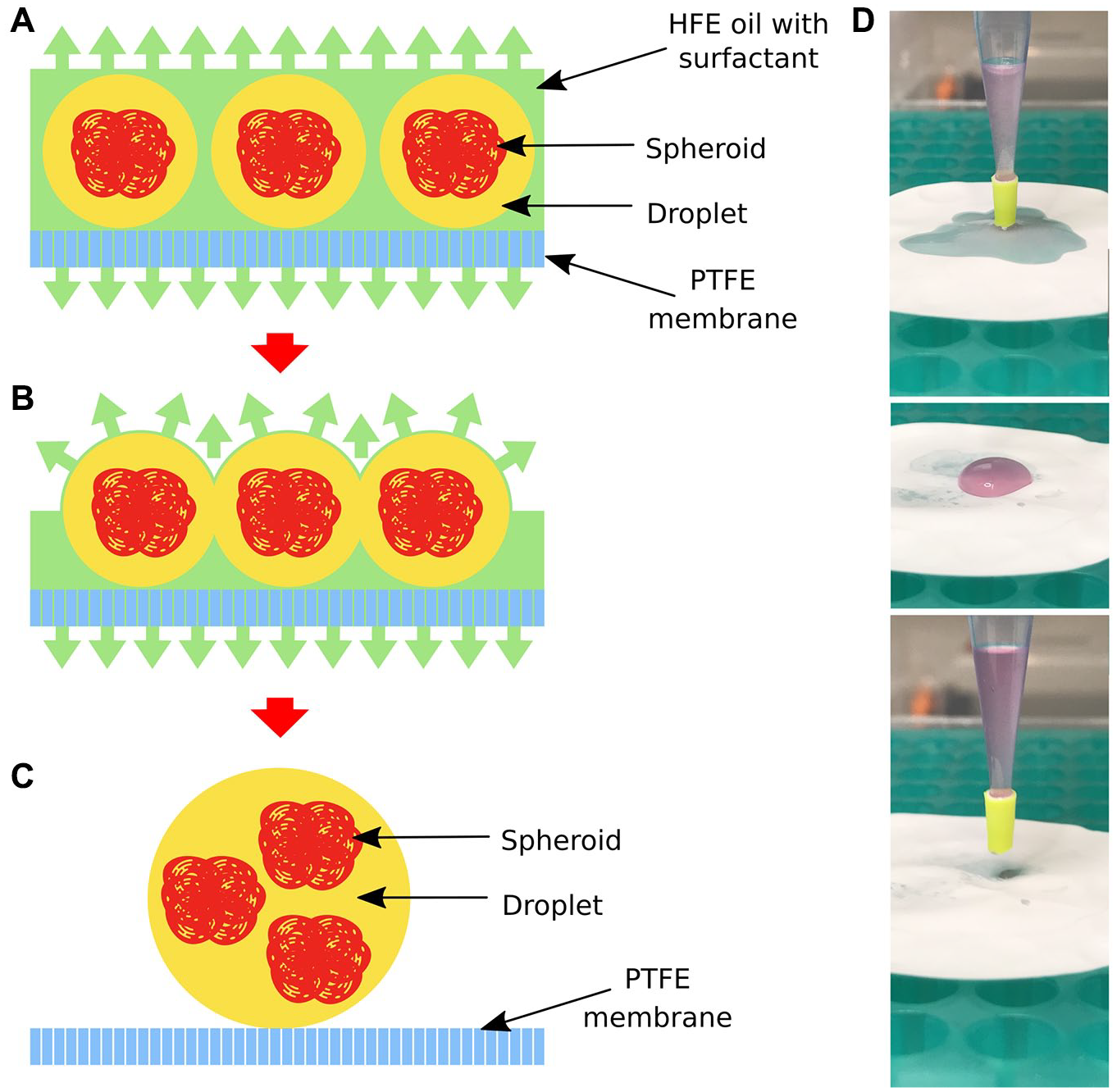
A membrane-based sample recovery process based on physical separation of two phases by an oil-attracting (oleophilic) and water-repelling (hydrophobic) membrane made of polytetrafluoroethylene (PTFE). (
The method presented here allows for a simple chemical-free sample de-emulsification for droplet microfluidics, which is inert to the cells. 54 This method stands in contrast to commonly used chemicals such as perfluorooctanol, which may interfere with the results of the biological experiments performed in droplets. 55 The membrane-based method is easy to scale up, is ready for automation, and does not affect the biological sample entrapped in droplets.
Spheroid Viability
Published results indicate that droplet microfluidics used in spheroid formation has limited impact on the viability of the cells entrapped and the spheroids formed in droplets.20,34 The majority of published droplet microfluidics–based spheroid-forming protocols rely on double emulsions34,41–43 or on adding hydrogels34,41–43 to the culture medium in which the cells aggregate.
To test whether the phase separation technique (membrane-based sample recovery) used to release the dispersed phase from the emulsion influences the overall viability of the cells that form spheroids, we used fluorescent viability stains. Cell viability was assessed by adding Hoechst 3334, propidium iodide, and Calcein AM mixture to the recovered spheroids in culture medium. Following 30 min of incubation in the dark, fluorescence microscopy images of the stained spheroids were acquired (in FITC, TRITC, and DAPI;
In the case of spheroids created with RT4 and A-431 cells (
We also have observed differences in the viability of the cells that have aggregated and were part of the formed and recovered spheroids.
In case of HEK cell–based spheroids, most of the dead cells were in the spheroids and not free-floating in the culture medium. In contrast, RT4 and A-431 cell–based spheroids were composed mainly of the cells that were alive: The measured viability of the cells forming spheroids was 99% and 98.8% for RT4 and A-431 cell–based spheroids, respectively. In both cases, the dead cells that were recovered from droplets were mainly free-floating in the culture medium.
The method used for spheroid recovery may also influence the overall viability of the biological content recovered from droplets. As a proof-of-concept experiment, we have recovered A-431 cell–based spheroids entrapped in droplets using either perfluorooctanol or the PTFE membrane–based method paired with the automated droplet microfluidic platform. All of the measured viability parameters were lower for the chemically recovered sample.
The overall viability of the recovered cell content was 87%, with a 9% drop in viability when compared to the 96% viability of the initial sample entrapped in droplets. At the same time, the A-431 cell–based sample recovered with a PTFE membrane–based method experienced only a 5.5% drop in viability. Also, the percentage of viable cells that were forming spheroids was 1% lower when compared to the sample recovered with an alternative PTFE membrane–based method (97.8% vs. 98.8%).
From the results of the proof-of-concept experiments, it seems that the newly proposed PTFE membrane–based method for sample recovery has a lower negative impact on the viability of the formed spheroids.
Characterization of the Cell Spheroids Produced Using Automated Droplet Microfluidics
To characterize cell spheroids, we have chosen to use the circularity and aspect ratio parameters of the recovered spheroids, because those parameters are somewhat independent of the number of cells forming cell aggregates. The circularity of the spheroids was analyzed using ImageJ’s Measure command, which computes circularity of an object according to the following formula: 4π × area / perimeter2, in which circularity of 1.0 indicates a perfect circle.46 The mean value of circularity of analyzed HEK, RT4, and A-431 cell–based spheroids was similar: 0.7, 0.69, and 0.68 [standard deviation (SD), 0.07, 0.09, and 0.11], respectively. The mean aspect ratio (height vs. width) of the spheroids of the three different tested cell lines was 1.37 (SD, 0.25, 0.25, and 0.24).
Both parameters indicate that the spheroids produced are not perfect spheres, as is evident from images (
Droplets form the closest packing of undeformed spheres at a volume fraction of 0.74. 45 Based on that estimation, about 26% of the densely packed emulsion generated by the automated droplet microfluidic platform was the continuous phase (HFE oil), and the remaining 74% was the dispersed phase (the spheroids suspended in culture medium). With a volume of 12.7 nL and a constant average number of cells in the generated droplets, we estimate that in one run, the robotically automated droplet microfluidic platform produces more than 17,000 droplets filled with HEK cells/spheroids. Since the duration of one run is 12 min, the robot can cycle five different samples in 1 h, generating up to 85,000 spheroids. This puts the estimated maximum capacity of the platform, at this stage of its development, at 120 different samples per day, which would result in producing 2.04×10⁶ spheroids in 48 h, because similar time is needed for the robot to recover the spheroids from the emulsion after overnight incubation.
Conclusion
This article presents a robotically automated droplet microfluidic platform that allows for production of cell spheroids independent from a human operator. The new platform was tested as an automated assembly line for scaffold-free HEK, RT4, and A-431 cell spheroids, allowing for generation of more than 17,000 spheroids in a single 12-min run. The system’s maximum throughput is 85,000 spheroids per hour. We also present a scalable method for sample recovery from the droplets, which eliminates the need for the use of chemicals for disrupting the emulsion and supports process automation. We believe that the low price of the main component of the robotically automated droplet microfluidic platform, the high production throughput, and the full automation of the process decrease the generation cost of a single spheroid to the scale needed for it to lead drug discovery screening, matching the costs at which spheroids could be used as building blocks for organ-scale regenerative medicine.
Supplemental Material
DS_TECH877376 – Supplemental material for Rapid Production and Recovery of Cell Spheroids by Automated Droplet Microfluidics
Supplemental material, DS_TECH877376 for Rapid Production and Recovery of Cell Spheroids by Automated Droplet Microfluidics by Krzysztof Langer and Haakan N. Joensson in SLAS Technology
Footnotes
Supplemental material is available online with this article.
Declaration of Conflicting Interests
The authors declared no potential conflicts of interest with respect to the research, authorship, and/or publication of this article.
Funding
The authors received the following financial support for the research, authorship, and/or publication of this article: The authors acknowledge funding from VINNOVA, the Knut and Alice Wallenberg Foundation, and the Novo Nordisk Foundation.
References
Supplementary Material
Please find the following supplemental material available below.
For Open Access articles published under a Creative Commons License, all supplemental material carries the same license as the article it is associated with.
For non-Open Access articles published, all supplemental material carries a non-exclusive license, and permission requests for re-use of supplemental material or any part of supplemental material shall be sent directly to the copyright owner as specified in the copyright notice associated with the article.