
Abstract
Precise metering in liquid dispensing applications often requires application-specific solutions due to incompatibilities of the sensor and actuator components with the dispensed liquids. Some reoccurring challenges are aggressive liquids that would damage the sensors or tubing, the need for sterile liquids while the pumps or sensors cannot be sterilized, or media that can clog the sensor channels. Two different dispensing systems are here presented where the dispensing flow rate or volume is indirectly measured through a coupled pressure change or airflow, thus avoiding contact between the sensor and liquid. The controlled pressure-driven dispensing (cPDD) system builds an overpressure in the liquid reservoir by pumping air and controls the opening of the liquid output valve based on the internal pressure development. The FlowCap system uses a liquid pump on the outlet, controlled by the measured inflow of air to the reservoir. Both systems are designed for compactness and portability and offer independent operation, as well as control and communication, over a wireless interface.
Introduction
In the design and manufacture of liquid dispensing systems, the selection of the wetted components is restricted by material compatibility with the liquids. This is particularly challenging in the case of the pumps and any flow sensors in the system.
A pump component’s flow rate often depends on properties of the dispensed liquids so that calibration is required for every liquid and for the operation conditions. Fixed-volume displacement pumps, such as syringe pumps, overcome this, but with compromises between flow-rate precision, refill time, and capacity, and they require cost-driving high-precision mechanical components. Additionally, such pumps have high mass-inertia and are therefore not suited for small-volume dispensing applications.
Indirect pumping remains an attractive principle, and if the pumped media can be a dry gas such as air, the requirements on the pump become easier to meet, especially for lifetime and cost.
One established indirect dispensing principle is time–pressure dispensing (TPD). Comprehensive studies have been dedicated to understanding the exact physics of TPD1,2 and especially to reducing the influence of syringe fill level on the dispensed liquid volume.
The use of flow sensors within the liquid dispensing path for closed-loop control reduces the precision requirement of the flow-driving components. The added cost of the sensor and control system is easily compensated by the lowered cost of the flow-driving components. The precision requirement is shifted to the sensor components. Also, for these flow sensors (in liquid contact with the dispensing media) the properties of the liquid influence the measured values and calibration is needed for every media and operation condition, and a wide material compatibility translates into high cost.
An indirect measurement principle where the measured media is a gas, such as air, can therefore avoid the need for calibration with different liquids, and at the same time improve the precision-cost factor. This is important if the liquids are, for instance, of varying viscosity. An emerging field of application for dispensing technologies is rapid prototyping in bio and biomedical sciences (bioprinting), where materials such as gelatin and hydrogels are dispensed3–5 and strong effort has been dedicated to understanding the flow behavior of such materials. 6 Observing the dispensed amount of liquid independently of the liquid properties becomes essential when dealing with these materials.
State-of-the-art dispensing systems are typically dispensing a fixed volume without verification of the actual dispensed volume, apart from in separate calibration processes. The described indirect volume measurement provides a real-time measurement of every dispensed unit or droplet volume, independent of the fluid’s material properties. This information can be transmitted in real time and be incorporated in larger control or quality assurance processes. The approach can be used for both Newtonian and non-Newtonian fluids.
Also, for stand-alone units connectivity options, such as wireless interface, are becoming important. Both presented systems include a wireless interface so that dispensing can be remotely controlled, as well as reporting dispensed volumes and the fill levels of the liquid reservoirs in real time.
Method and Design
Controlled Pressure-Driven Dispensing System
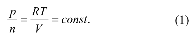
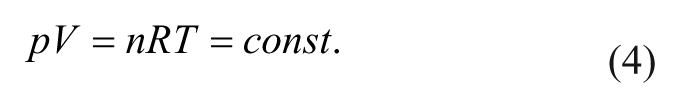
The controlled pressure-driven dispensing (cPDD) 7 operates by generating an overpressure inside a partially filled container and monitoring the pressure gradients of the gas volume while the liquid escapes through a dispensing valve ( Fig. 1 ). Two major functionalities are required to be able to dispense a given amount of liquid out of the container. First, the amount of gas within the container has to be determined. While compressing, assuming an isothermal process, the ideal gas law can be formulated as
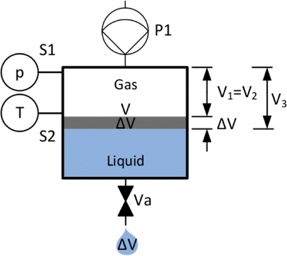
Dispensing principle. The pump P1 first generates an overpressure in the containment. The dispensing valve Va is opened as long as needed to reach the target pressure, equivalent to the target dispensing volume.
Hence, it follows that
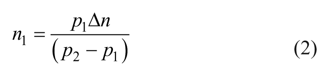
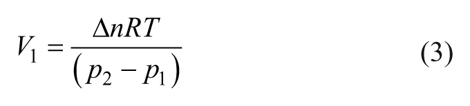
where V1 is the gas volume within the containment, Δn is the mass transported into the system during the compression phase, R is the gas constant, T is the temperature, and p1 and p2 are the pressure values before and after compression, respectively. Hence, the gas volume, V1, can be estimated by observing the pressure development during compression and the number of particles (Δn) pumped into the container. The number of particles, or mass, is in the presented system determined through calibration of the compression pump or by calibration of a gas flow sensor that does not depend on or get into contact with the dispensing liquid.
The dispensing itself can be controlled by observing the pressure drop within the gas volume V1 = V2 with the ideal gas law:
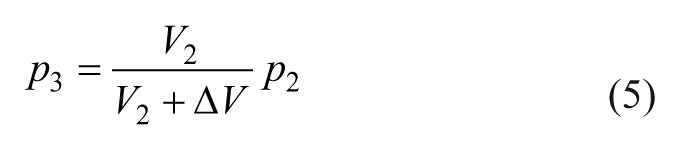
where V2 is the gas volume before dispensing, V3 = V2 + ∆V is the gas volume after dispensing, and p2 and p3 are the absolute pressure before and after dispensing, respectively.
The dispensing system can therefore wait for the internal pressure to reach the target pressure, p3, corresponding to the intended volume change of the gas volume ( Fig. 2 ). A controlled dispensing of liquid is thus realized with the help of a pressure sensor within the gas volume, without flow sensors in the liquid path, which is a major advantage when dealing with aggressive liquids or liquids sensitive to contamination.
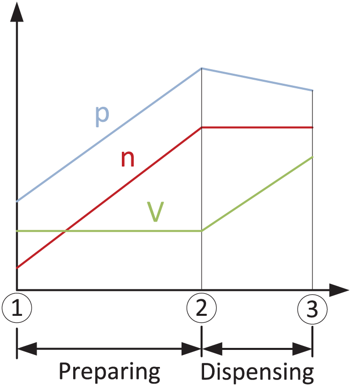
Pressure, mass, and volume evolution during compression and dispensing.
By adding multiplexing valves, one control unit can be shared between several containers, requiring only two valves per container ( Fig. 3 ).
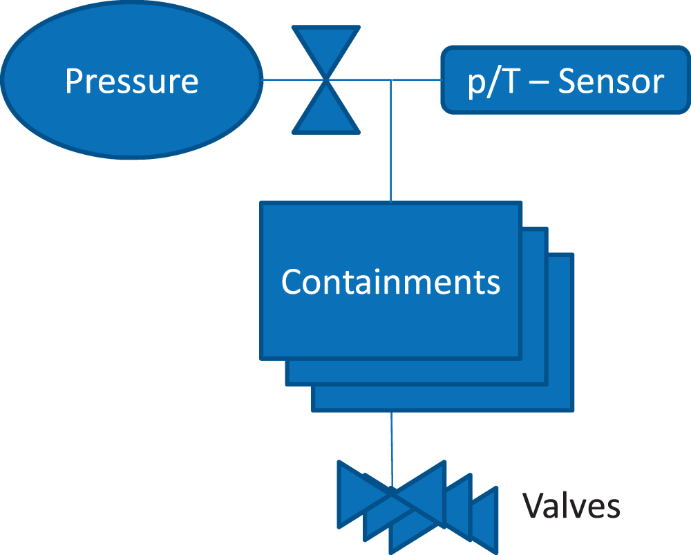
System schematic showing how multiple containments can share one pressure and sensor system.
The presented cPDD unit is built as a compact bottle-cap module fitting any reservoir bottle with GL-45 neck threads ( Fig. 4 ). The housing and mechanical support structures are 3D printed. The module incorporates an air inlet pump (a CTS E129-13-090 membrane pump from Parker, Hollis, New Hampshire, USA) for compression, a dispensing valve, a control board, and rechargeable batteries ( Fig. 5 ). The control board integrates a microcontroller, a wireless interface chip, and driver circuitry for the pump and valves. The microcontroller administrates the compression and dispensing process and performs the sensor signal evaluation and numerical integration. A simplified state diagram of the dispensing algorithm is shown in Figure 6 .
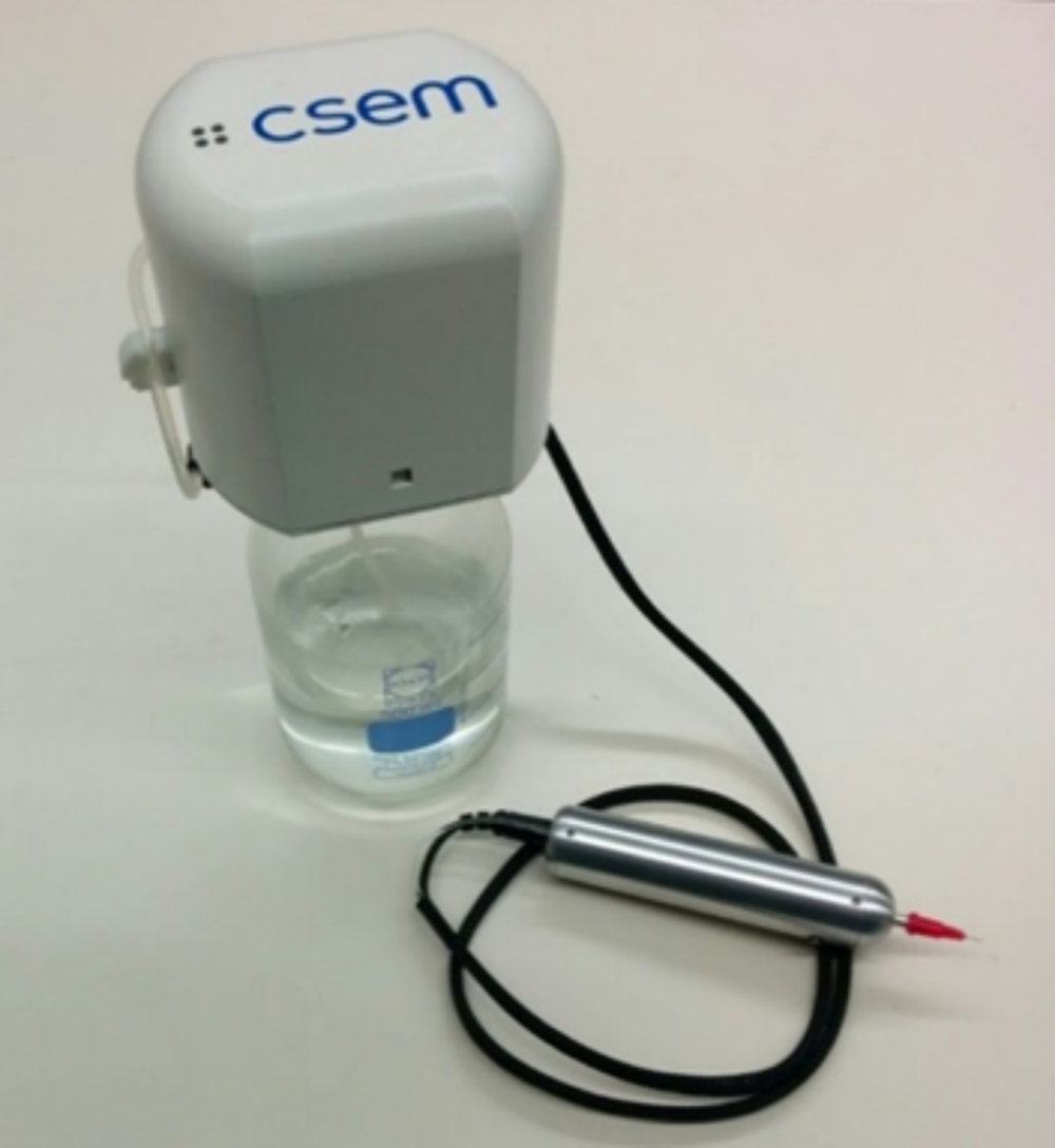
The cPDD demonstration unit, with a dispensing pen.
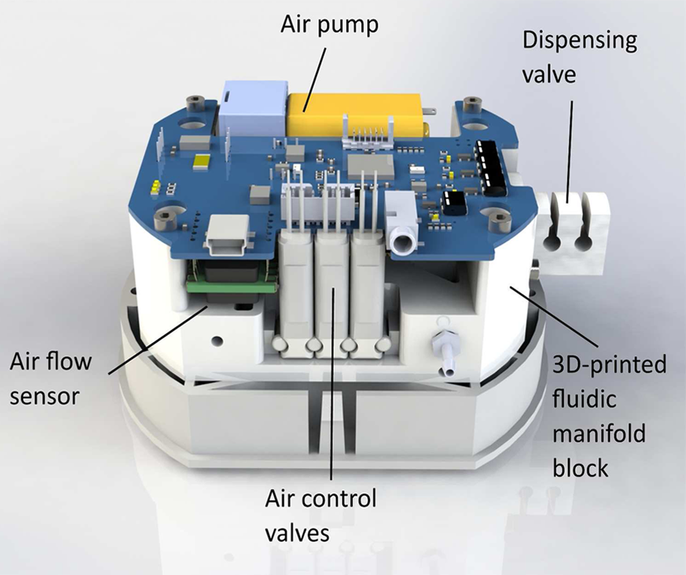
Software-rendered cPDD module with air pump, air control valves, airflow sensor, control board, and dispensing valve.
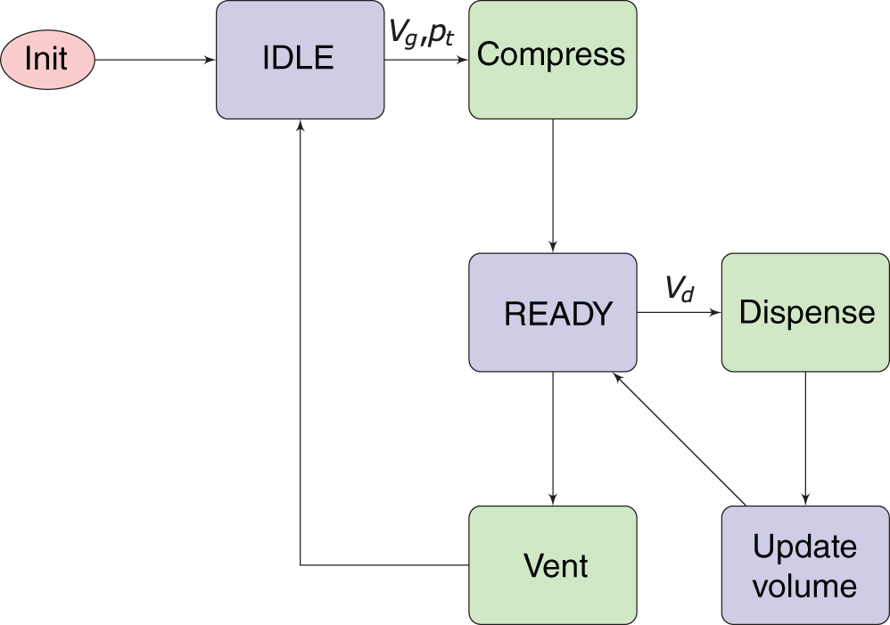
Simplified state diagram of the microcontroller dispensing algorithm.
The Microchip (Chandler, Arizona, USA) PIC24FJ128 microcontroller was chosen for its included 24-bit sigma-delta analog–digital converter used for reading the pressure sensor data, as well as built-in USB connectivity. Calibration data are stored in the microcontroller. The wireless interface and TCP/IP stack is provided by a Microchip RN171 Wi-Fi module. Through use of a simple application programming interface (API) over USB or the wireless interface, the dispensing operation can be controlled and real-time information about the dispensed volume and bottle-filling level can be read out. In the case of multiplexed containments, the valves connected to the containment are interfaced via inter-integrated circuit (I2C) communication.
Indirect-Flow-Rate Metering System (FlowCap)
In the FlowCap dispensing system, a pump dispenses liquid from a partially filled reservoir bottle while the resulting underpressure is equilibrated through an air channel to the outside environment. An airflow sensor in the channel allows determination of both the dispensed volume and the filling degree of the reservoir.
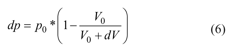
The numeric integration of the airflow is directly translated into the volume of dispensed liquid since the volume of liquid that leaves the bottle is entirely replaced by air flowing into the bottle, whereas the dynamics of the airflow is also shaped by the flow resistance of the air channel and the amount of air inside the bottle. The smaller the air volume (V0) is in the bottle, the larger the maximum flow rate observed by the flow sensor, since the flow rate is proportional to the pressure drop (dp) provoked by the volume (dV) leaving the bottle, as per
A system calibration will be independent of the actual liquid to be dispensed.
FlowCap is built as a bottle-cap module fitting GL-45 neck thread bottles, hosting the liquid pump, valve, airflow sensor, and control board ( Fig. 7 ). The control board is based on a BeagleBone Black (BeagleBoard.org Foundation, Oakland Twp, Michigan, USA) single-board computer (SBC). The BeagleBone was selected for its peripheral real-time units (PRUs). The PRU is an onboard microcontroller that is useful for real-time operations where the main CPU cannot guarantee low enough latency. The PRU can access memory shared with the main CPU and is here used to implement a direct memory access (DMA) transfer from the sensors over an serial peripheral interface (SPI) interface. The PRU analyzes the sensor signal and directly controls the pump to synchronize sampling of the sensors and actuator control.
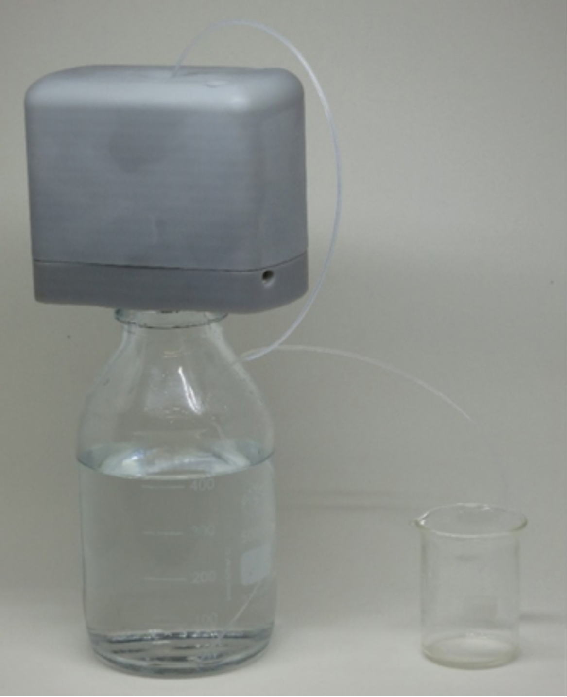
The FlowCap demonstration unit, used together with a 500 mL bottle.
The pump parts in contact with the liquid are made of chemically resistant polyvinylidene fluoride (PVDF) polymer and perfluorinated elastomer (FFPM) elastomer, and the tubing leading into and out of the pump is made of polytetrafluoroethylene (PTFE).
In the presented configuration, the flow sensor is based on a differential pressure sensor measuring the pressure drop over a flow constriction. The sensor sensitivity dictates the minimum flow constriction needed and therefore affects the response time. Here, a First Sensor (Berlin, Germany) LDES025U differential pressure sensor equipped with an integrated 16-bit analog–digital converter and SPI interface is used. Its measurement range of only 25 Pa allows a low-pressure-drop constriction design that does not notably slow down the compensating gas flow. Additionally, the used sensor has a high burst pressure of 5 bar, making it very robust against misuse and external mechanical shocks.
Results and Discussion
cPDD System
The bottle-cap implementation of the cPDD was tested by dispensing with target volumes between 100 µL and 3 mL. The resulting volumes were verified by a high-precision Mettler Toledo (Greifensee, Switzerland) XP56 scale. Figure 8 shows the measured volumes (based on weight) as a function of targeted volume, as well as the mean value (black dot) and standard deviation (gray area).
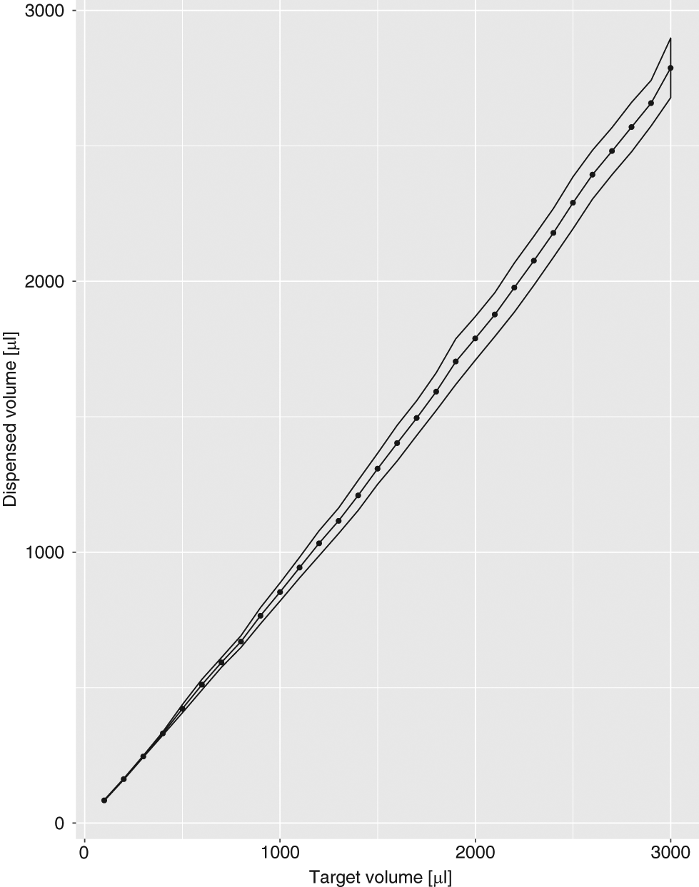
Dispensed volume versus target volume. The dispensed volume values have been scaled to match the range of the target volumes.
The results indicate that the standard deviation is directly proportional to the dispensed amount of liquid. Even though the tested volumes in the described setup are in the milliliter range, it can be seen from the obtained results—as from the governing equations—that the described control principle can be scaled down and used for droplet sizes in the microliter or even submicroliter range.
The standard deviation of dispensing experiments is better than 3% over the tested range. However, a factor between the target and dispensed volume is decreasing the overall accuracy of the conducted experiments. This factor can be explained by an erroneous estimation of the gas volume, Vg, leading to an incorrect target pressure value, p2, and therefore incorrectly dispensed volumes.
In view of this finding, one way to improve the system’s performance is to replace the procedure used for calibrating a pump to estimate the system’s gas volume with a more stable implementation utilizing a flow sensor on the gas inflow side of the experiment. Second, adding a valve in front of the containment’s air inlet and measuring the pressure difference across this closed valve while dispensing will permit the use of relative pressure sensors, which can be engineered to have a pressure range that fits the expected pressure drop of the targeted volumes.
FlowCap System
The FlowCap system was tested with dispensing volumes from 9 to 22 µL, and at different filling levels in the reservoir bottle of 50–250 mL. Figure 9 shows the precision of dispensed volume as a function of filling level. In this measurement series, the filling levels were determined by weighing the bottle and were not calculated from the sensor signal. For smaller filling levels, and thus larger gas volume, the precision becomes lower as the ratio between the dispensed volume and gas volume increases.
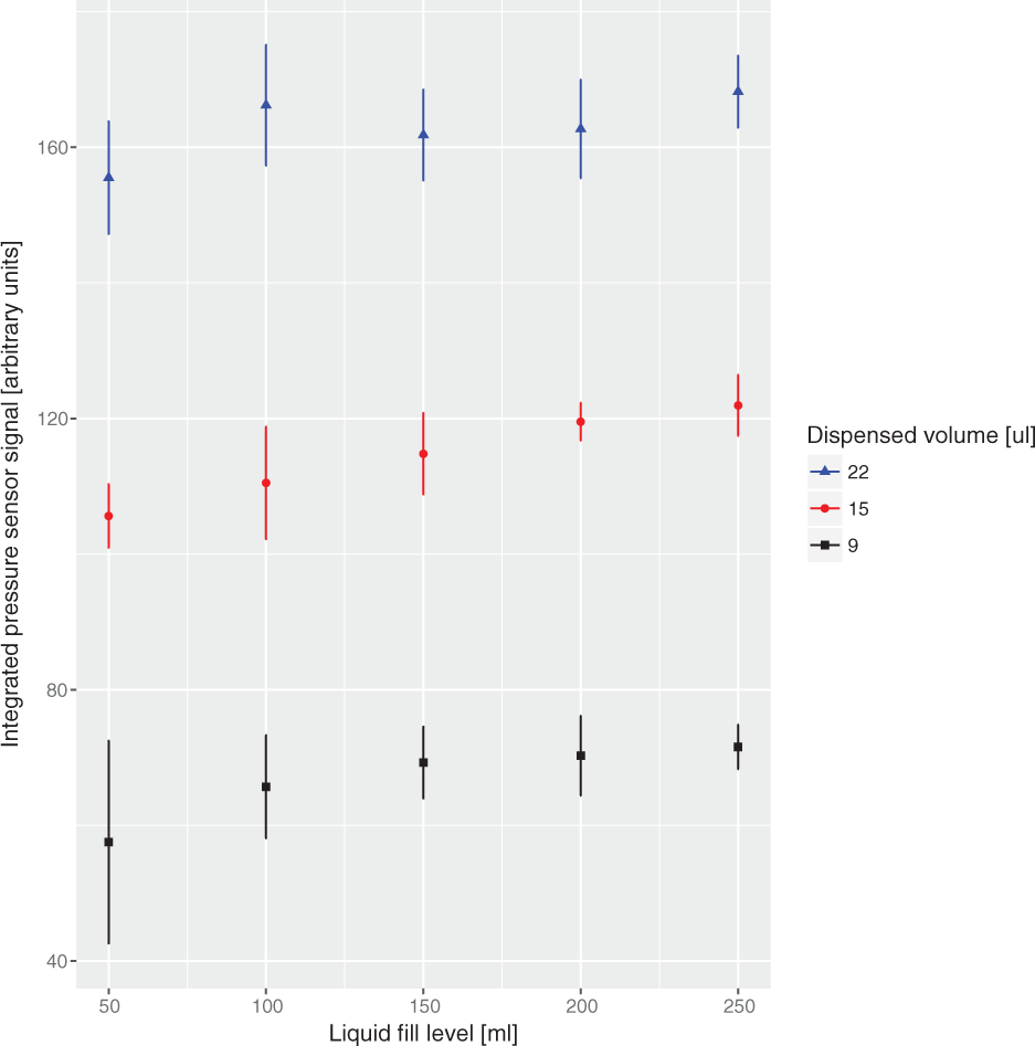
FlowCap dispense volume reproducibility test.
The airflow dynamics are illustrated in Figure 10 for two different filling levels. It can be seen that the signal recording time (and thereby integration time) was limited—especially for smaller liquid levels in the reservoir (50 mL), for which it was not sufficiently long (i.e., signal level being above the starting signal level at the end of the experiment). This is due to a constant recording time applied during the experiments. We further tried to apply an automatic detection of settled inflow to control the duration. However, ambient pressure fluctuations made this detection unreliable.
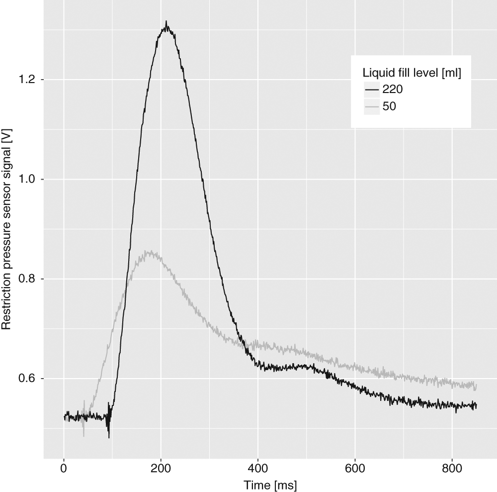
FlowCap airflow sensor signal evolution, for bottle fill levels of 220 mL and 50 mL.
Keeping the insufficient recording time in mind, one can also find an explanation of the tendency for decreasing integral values in Figure 9 for smaller liquid fill levels, as the induced flow becomes slower for bigger gas volumes (smaller liquid fill levels) and longer times are required to compensate the created pressure difference over the sensor restriction; thus, the measurement period becoming insufficient to capture the whole compensation process.
For the measurement principle, it is very important to reduce pressure fluctuations, as the fluctuations make a reliable estimation of the inflow settlement difficult. Incorporating a dampening filter or a gas reservoir as a pressure reference can improve the measurement resolution and sensitivity. Future research will focus on stabilizing the airflow to enable high accuracy and reaching the submicroliter range.
Still, the described process has two major advantages:
The dispensed volume can be measured directly by the flow through a gas flow sensor.
A calibration based on the flow peak amplitude allows determination of the filling level.
It is also noteworthy that the FlowCap system does not require a reservoir or container to be pressurized, which means the measurement method can in principle be applied to any tank dimension (even oil terminal tanks).
Conclusion
Two laboratory dispensing systems have been designed with high portability and low component cost in mind, relying on microcontrollers for performance, stand-alone operation, and real-time communication features.
In both systems, the use of an indirect metering scheme reduces the material compatibility requirements on the sensor components as it shifts the critical characteristics from the wetted components to the airflow sensor. The real-time processing in the embedded microcontrollers is crucial to the operation of the systems, and the closed-loop control improves the accuracy of the systems while allowing lower-cost components to be used.
For instance, in bioprinting applications, where the liquids are sensitive to contamination and have varying material properties, a controlled dispensing procedure that enables the quantitation of each produced droplet is of major advantage. Process data can be gathered in real time and provide feedback vital for the success of a conducted experiment.
Further development is ongoing toward dispensing smaller liquid volumes and improving the resolution and accuracy of the described dispensing approaches.
Footnotes
Declaration of Conflicting Interests
The authors declared no potential conflicts of interest with respect to the research, authorship, and/or publication of this article.
Funding
This work was funded through the European project BIOFOS (FP7-ICT-2013-10, grant number 611528), and the MCCS and the cantons of central Switzerland. CSEM thanks them for their support.