
Abstract
Contact heat evoked potentials (CHEPs) are recorded from the brain by giving thermal stimulations through heating pads kept on the surface of the skin. CHEP signals have crucial diagnostic implications in human pain activation studies. This work proposes a novel design of a digital proportional integral (PI) controller based on Arduino microcontroller with a view to explore the suitability of an electric heating pad for use as a thermode in a custom-made, cost-effective CHEP stimulator. The purpose of PI controller is to set, regulate, and deliver desired temperatures on the surface of the heating pad in a user-defined pattern. The transfer function of the heating system has been deduced using the parametric system identification method, and the design parameters of the controller have been identified using the root locus technique. The efficiency of the proposed PI controller in circumventing the well-known integrator windup problem (error in the integral term builds excessively, leading to large transients in the controller output) in tracking the reference input and the controller effort (CE) in rejecting output disturbances to maintain the set temperature of the heating pad have been found to be superior compared with the conventional PI controller and two of the existing anti-windup models.
Introduction
Thermal stimulation of the sensory nerve fibers on the skin surface elicits electric potentials in the brain, known as contact heat evoked potentials (CHEPs),1,2 which could be recorded in electroencephalograms (EEGs). Similar to the study of any other evoked responses (auditory, visual, and somatosensory) recorded in EEGs, the heat stimuli are presented in a repetitive fashion to subjects in order to use the conventional trigger locked averaging procedure3,4 to extract the CHEP associated with the presentation of the thermal stimulus by significantly suppressing uncorrelated noise, which is inevitably present in the measured EEG data. The study of CHEP signals is essential to understand the level of mediation of the nociceptive receptors of the sensory neurons in responding to the pain stimulus in a variety of neurological dysfunctions, including neuropathy.1,2,5–7 Typically, temperatures of the order of 50 °C are used to present a thermal stimulus on the skin surface using either a fast-acting heat foil thermode1,2,5–7 or a laser pointer8,9 in CHEP stimulators. Regulation of the current passing through the thermode (the heating element) using a control mechanism is necessary to engineer the CHEP stimulator for safe practical use.
Commercial CHEP stimulators have thermodes with a rapid rising time of 70 °C/s in delivering the stimulus without any delay or heat loss to the skin surface of subjects. These fast time domain specifications of the sophisticated thermode designs allow the CHEP stimulator to deliver the heat as a series of repetitive pulses at a predefined rate dictated by the user-desired interstimulus time interval (ITI), which is the time interval between successive stimuli in any stimulus presentation system during a typical evoked response EEG experiment.
However, the ITI for pain studies has been recommended to be set at a slower rate of 0.05–0.1 Hz (i.e., one heat pulse in 10–20 s) to prevent very frequent exposures of the skin surface to heat stimuli, which has the potential to result in cutaneous lesions. Considering the necessity of delivering the heat stimulus at a significantly slower repetition rate irrespective of the fast response time of the thermode, it may be expected that even a movable thermode coupled to a linear actuating shaft (controlled by a motorized mechanism operating at slow speed) might accomplish the task of delivering heat in a pulsed manner as an alternative to the fixed thermode with tunable heat output in commercial CHEP stimulus presentation systems.
As a part of this idea, the present work explores the feasibility of using a simple electric heating pad with slow response time as a thermode in a CHEP stimulator. A comprehensive analysis has been performed to understand the output characteristics of the heating pad, and based on this analysis, a suitable digital proportional integral (PI) control system has been designed for controlling its heat output. Taking into account the limitation in the thermal dynamics of this heating pad (with an intrinsic slow heating rate), the proposed system design attempts to optimize the performance of the CHEP stimulator by meeting the following two essential specifications of the heat control system:
The settling time (
In the presence of environmental effects, the heating pad is likely to lose its surface temperature (typically 1–2 °C) and is exposed to short-term temperature fluctuations due to external disturbances and intermittent contact with the skin surface; the controller effort (CE), which is associated with the ability of the controller to reject these disturbances, should therefore be designed to be fast enough in correcting the temperature to the set value within ITI (typically 15 s).
The control system design described in this article justifies the suitability of the heating pad for use in a CHEP stimulator by highlighting two important improvements that have been incorporated in the design to stabilize the user-desired set temperature. First, an anti-windup structure that limits the overshoot in the settling time of the temperature of the heating pad has been incorporated, and second, the design of the CE has been improved. The incorporation of both improvements in the proposed control system has yielded performance that is superior to that obtained using a conventional PI controller, and two popular anti-windup models described in the literature.
Materials and Methods
An electric heating pad (SparkFun Electronics, Niwot, CO) constructed out of a mesh of polyester filament and micrometal conductive fibers folded into a protective polyimide film with a resistance of 8.5Ω is used in the present work. An N-Channel MOSFET P55NF06 (STMicroelectronics, Geneva, Switzerland) is used as an actuator to supply variable current to control the temperature of the heating pad. The PI controller is realized using an Arduino Mega 2560 microcontroller. 10 This microcontroller can receive an 8-bit pulse width modulation (PWM) signal at its pins, which is used to generate a corresponding variable analog voltage to control the heating current. To measure the temperature of the heating pad, a commercially available analog temperature sensor, namely, LM35 (Texas Instruments, Dallas, TX), having a precision of 0.5 °C, is used in this work. The parameters, such as settling time, rise time, and steady-state errors, were assessed at the output of the controller considering the conventional definitions of each of the control parameters as used in the standard control system literature.11,12
The design of the control system for the heating pad involves the following steps:
System identification: Identifying the first-order and second-order transfer functions of the heating pad by measuring its output characteristics.
Design of a PI controller and anti-windup structure: Designing the system parameters to meet the time domain specifications of the identified system by using the root locus pole estimation method.
Digital realization and implementation of the PI control system with an anti-windup structure to control the temperature of the heating pad using the microcontroller.
Each of these steps is explained in the subsequent sections under major and minor subheadings.
System Identification: Electric Heating Pad
To precisely control a process, a mathematical model that represents the dynamic behavior of the system is essential.11–14 However, due to the complexity involved in obtaining the mathematical model of the heating pad by physical–mathematical analysis, the parametric system identification method has been used in this work by measuring the input–output characteristics. A standard system model has been fitted to the measured characteristics of the system to estimate the model parameters.
The output characteristics of the heating pad are obtained by passing a step current of 0.5 A, which is equal to one-third of its rated current (at 12 V DC supply), through the heating pad, and the temperature response is recorded for 80 min. The inevitable miniscule time delay in the rise of the step current from 0 to 0.5 A of the power supply is neglected in the system identification calculations. Figure 1 shows the measured open-loop response of the heating pad to the applied step input. From this measured step response, the step-response curve method 13 is used to get the approximated first-order transfer function, and the algebraic method 15 is used to get the approximated second-order transfer function of the heating pad.
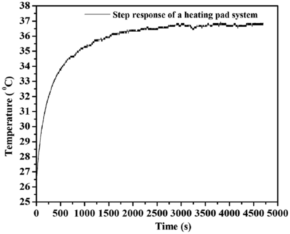
Measured step response of the heating pad system.
First-Order System Identification
Taking

where K and T are the open-loop gain and the time constant of the system, respectively.
The Laplace transform of the output is given by

where
Since the initial value of the step response is nonzero (as shown in
Fig. 1
), it is shifted to the origin by a value of
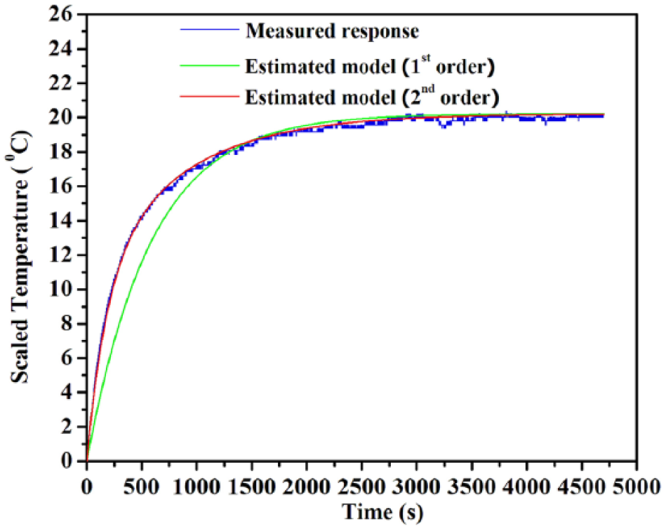
Step responses of the measured system (blue), estimated first-order model (green), and estimated second-order model (red) of the heating pad system.
According to final value theorem, we have

The value of
After applying inverse Laplace transforms to eq 2, it reduces to

For calculating the time constant (T), coordinates of any two points

We have taken 10 sets of coordinates above and below the inflection point and averaged the obtained time constants to get the optimum time constant

By substituting the open-loop gain and time constant values into eq 1, the estimated first-order transfer function of the electric heating pad system

The step responses of the measured and estimated first-order transfer functions are given by
To quantitatively evaluate the goodness of fit of the estimated model, the normalized mean square error (NMSE) is calculated:

where
NMSE for the estimated first-order model is 0.8992, indicating a reasonably good fit, which can be further improved using a second-order transfer function as a possible model.
Second-Order System Identification
The detailed procedure for identifying the second-order transfer function can be found elsewhere. 15 Here we give the final expression for the second-order transfer function as
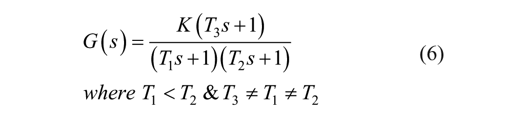
where K is the open-loop gain and
The open-loop gain (K) of the system is calculated to be 20.2 by following a procedure similar to that used for estimating the first-order transfer function for the system.
After applying inverse Laplace transforms to eq 2, it reduces to
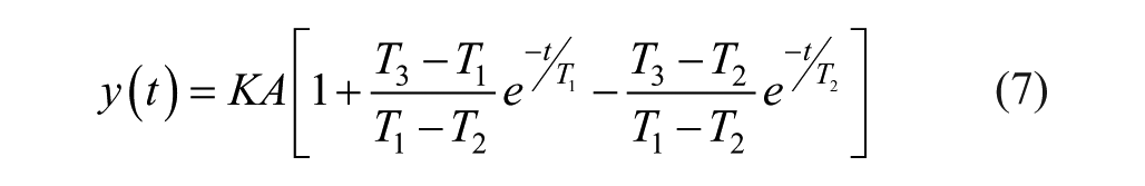
Taking three different points from step response


where


With this notation, eqs 8–10 may be substituted to determine the three unknowns,


where
The time constants of the system are calculated by substituting the values of
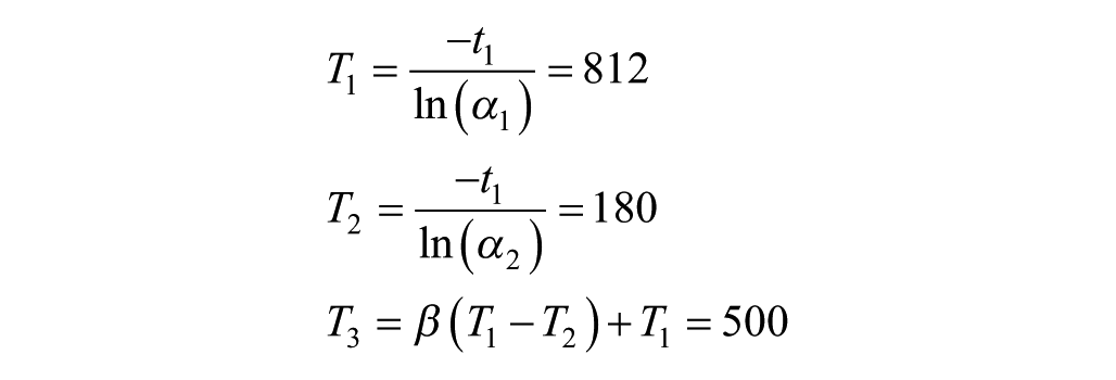
We have taken 100 sets of coordinates over the measured response (origin shifted and normalized) and averaged the obtained time constants
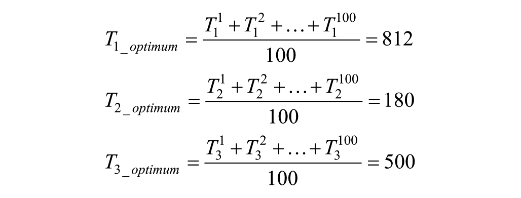
By substituting the open-loop gain and time constants into eq 6, the estimated second-order transfer function of the electric heating pad system is given as follows:

The step responses of
The NMSE, as defined in eq 5, is calculated to be 0.9967 for the second-order system. Hence, it is evident that the output response of the heating pad closely resembles that of a second-order system.
Discrete PI Controller Design
Estimation of PI Controller Parameters Using Root Locus-Based Pole Placement Technique
The placement of the poles of a closed-loop system could be tailored to meet the desired time domain specifications using the root locus pole placement technique. A detailed description of this technique may be found in the literature.16,17 Using this technique, the dominant complex conjugate poles corresponding to the envisaged time domain specifications (settling time of 4 s for unit step input and damping ratio of 0.8) for the heating pad are
The intrinsic heating rate of the heat pad is found to be 0.5 °C/s by passing maximum rated current through it. We chose a settling time of 4 s for a rise in temperature of 1 °C from room temperature (~25 °C). The choice of damping ratio is in general a trade-off between the maximum percent overshoot and the time at which the peak overshoot occurs. The optimal choice of damping ratio has been extensively evaluated for its suitability for the present work and has been found to be 0.8.
The open-loop transfer function of uncompensated system is given by

The general form of the transfer function of the PI controller is given by
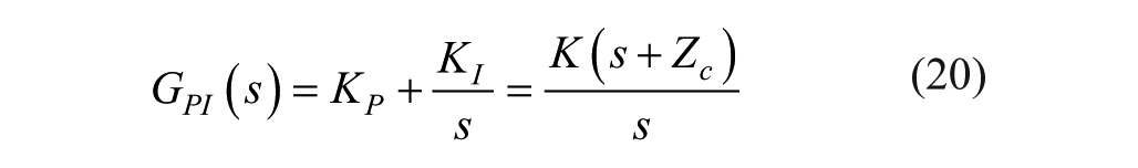
where
The open-loop transfer function of the compensated system is given by
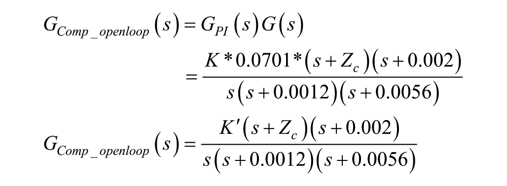
where
To obtain the desired parameters for the PI controller, the root locus plot of the system has been shifted to pass the desired complex conjugate poles
Therefore, the value of the PI controller gain is K =
The transfer function of the PI controller is
From the above transfer function of the PI controller, the corresponding proportional and integral parameters are obtained by comparing with eq 20;
The closed-loop transfer function of the compensated system is given by
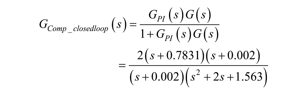
The closed-loop poles and zeros of the compensated system are given by

The effect of the dominant pole
With the obtained values of
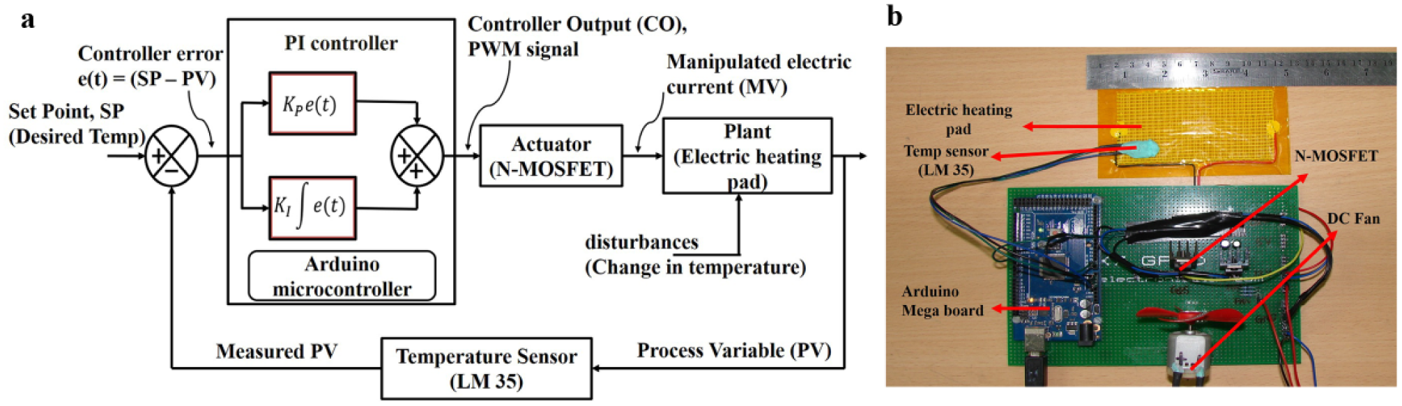
Figure 3a,b shows the schematic and the actual photograph of the designed PI control system for the heating pad. The PI controller with proportional and integral blocks that are realized using an Arduino microcontroller, the N-channel MOSFET that acts as an actuator for the heating pad, and the temperature sensor that measures the actual temperature of the heating pad are illustrated schematically in Figure 3a . A DC fan is used to avoid overheating of the MOSFET, as shown in Figure 3b .
(
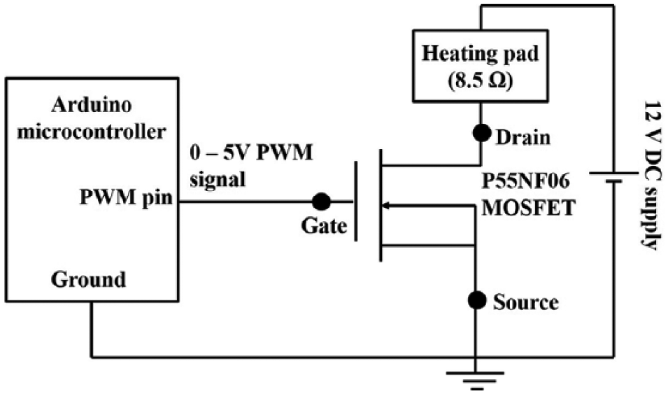
Figure 4 shows the block diagram of the control logic of the MOSFET actuator, which is configured to operate in common-source mode to regulate the temperature of the heating pad. The output of the PI controller algorithm is mapped to the PWM pin of the microcontroller. The 8-bit PWM pins of this microcontroller can generate analog voltages in the range of 0–5 V in proportion to the digital values at these pins (0–255), similar to a digital-to-analog converter (DAC), and the resulting analog voltage from the PWM pin is fed to the gate terminal of the MOSFET. Since MOSFET is a voltage-controlled current output device, the resulting drain current passes through the heating pad.
Block diagram of current control logic in heating pad temperature control system.
Proposed Anti-Windup Structure for the PI Controller
When the control system operates over a wide range of conditions beyond the expected range 0–255 (the DAC limit of the PWM pins), the system output tends to saturate and will be forced to operate in the open-loop mode. The integral term and controller output may then become very large. The control signal (saturated controller output) will then remain saturated even when the error signal (difference between desired output and set point) changes sign, and it may take a considerably long time before the integrator and the controller output come within the saturation range. This would lead to large transients at the output of the controller, causing momentary excursions in the output of the element that is to be controlled. In control system design, this situation is commonly referred to as integrator windup.18,19
Figure 5
shows the block diagram of the proposed anti-windup structure. The system has an extra feedback path that generates an error signal
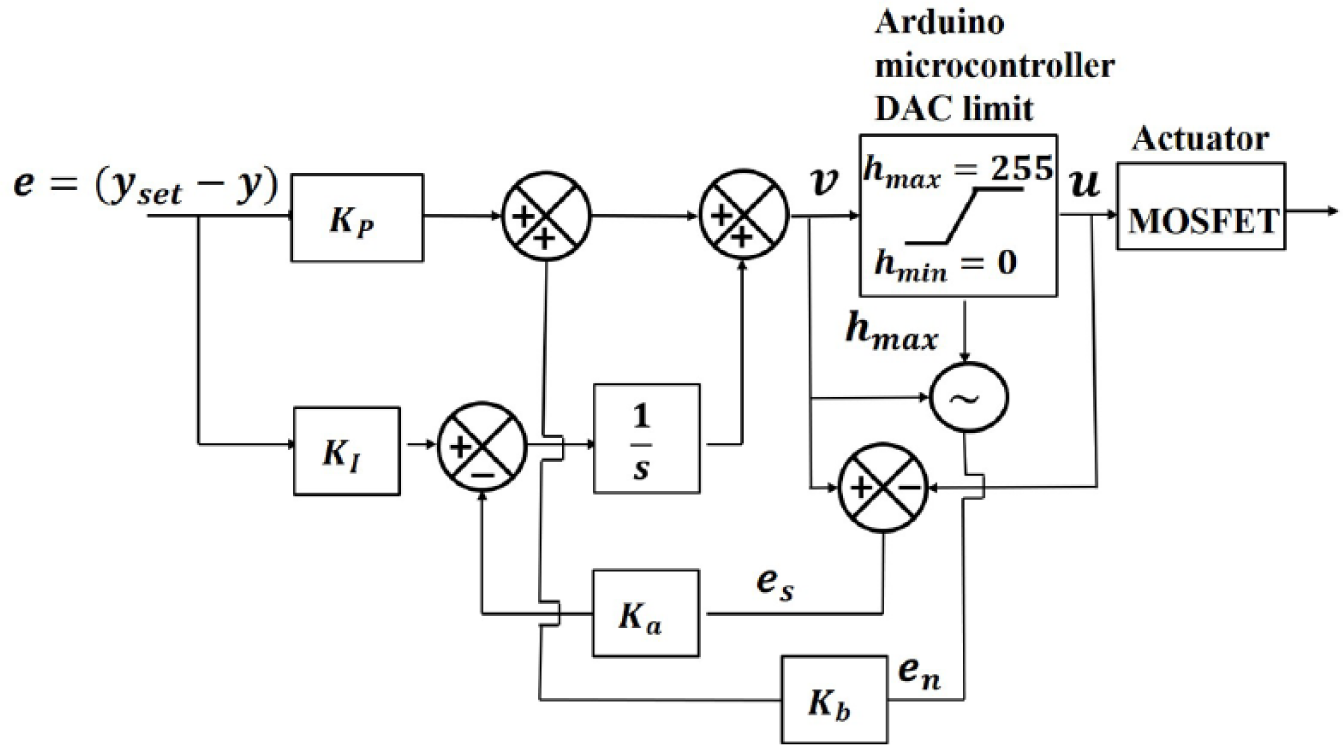
Block diagram of the proposed anti-windup structure.
Digital Representation of the PI Controller with the Proposed Anti-Windup Structure
The parallel form of the PI controller is given by

where the error
The proportional controller term in discretized form is given by

With the proposed anti-windup structure, eq 22 reduces to

The integral part in eq 21 is discretized using the trapezoidal rule of integration and is given by
where
Since the heating pad system is a very slow process, eq 24 can be approximated as

With the proposed anti-windup structure, eq 25 reduces to
The discrete form of the PI controller with the proposed anti-windup structure is given by
Equation 27 represents the discrete form of the PI controller along with the anti-windup feature realized in the integrated development environment (IDE) of the Arduino microcontroller. 10 The PI controller algorithm utilizes the past and present values of the error signal of the controller, along with the loop gains of the proportional and integral terms executed at each sampling instant of the control loop, to track the user-desired set temperature of the heating pad, as illustrated in Figure 5 .
Results and Discussion
The working of the proposed PI controller was demonstrated by using it to track a user set temperature of 50 °C (as in a typical CHEP stimulator1,2,5–7) over the heating pad. The performance of the proposed system was also compared with that of a conventional PI control system without any anti-windup structure, a PI with back-calculation anti-windup
20
(BCAW), and another with variable structure anti-windup
21
(VSAW). These anti-windup structures were also designed to achieve time domain parameters similar to those of the proposed PI control system to match the output characteristics of the heating pad.
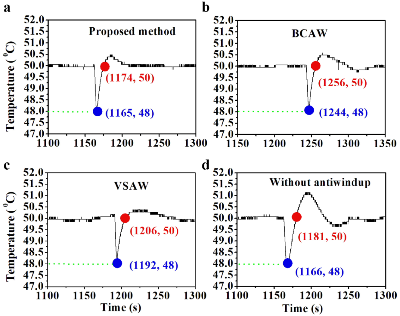
Figure 6
shows the output temperature of the heating pad controlled by the different types of PI controller systems investigated in this study. As seen from
Figure 6
, the settling time of the proposed PI control system is 130 s, which represents a significant improvement in the response of the heating pad compared with the conventional PI controller and two of the existing anti-windup models. It is evident from the
Figure 6
that each PI control system investigated in this study achieves some improvement in the settling time, but each design yields a slightly different settling time. However, the conventional PI controller (without anti-windup) achieves a stabilization in the set temperature with a large overshoot, causing the settling time to be as high as 412 s, and makes the system difficult to use for practical applications. This conspicuous overshoot in the temperature also justifies the necessity of incorporating the anti-windup structure in the PI control system. As expected, the two conventional anti-windup models, namely, the PI with BCAW and the PI with VSAW, exhibit reasonably stable output responses without overshoots. Out of the two anti-windup models, the BCAW shows a settling time of 145 s, which is slightly higher than that provided by the proposed PI system, which incorporates a novel anti-windup feature, reported here for the first time.
Figure 7
shows the temperature of the heating pad during a deliberate effort to disturb the temperature output of the heating pad to check the effort taken by the controller in quickly responding to such transient disturbances. A disturbance of the order of
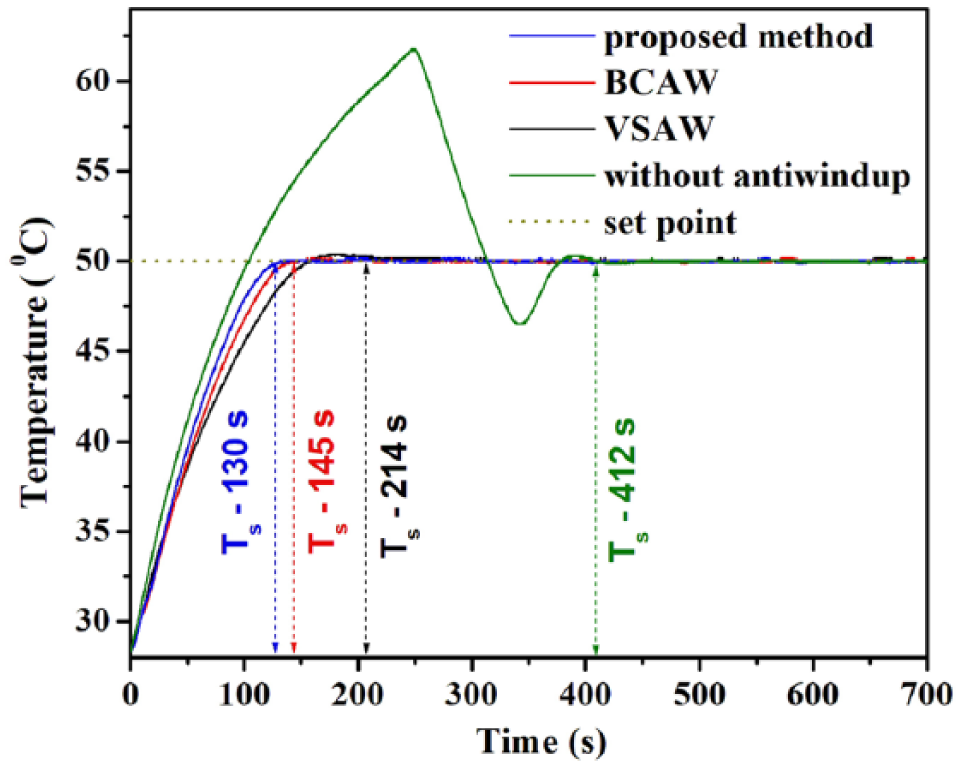
Reference tracking capabilities of proposed method (blue), PI with BCAW (red), PI with VSAW (black), and conventional PI controller (green).
Output disturbance rejection capability of the controller: (
Performance Parameters of Different PI Controllers.
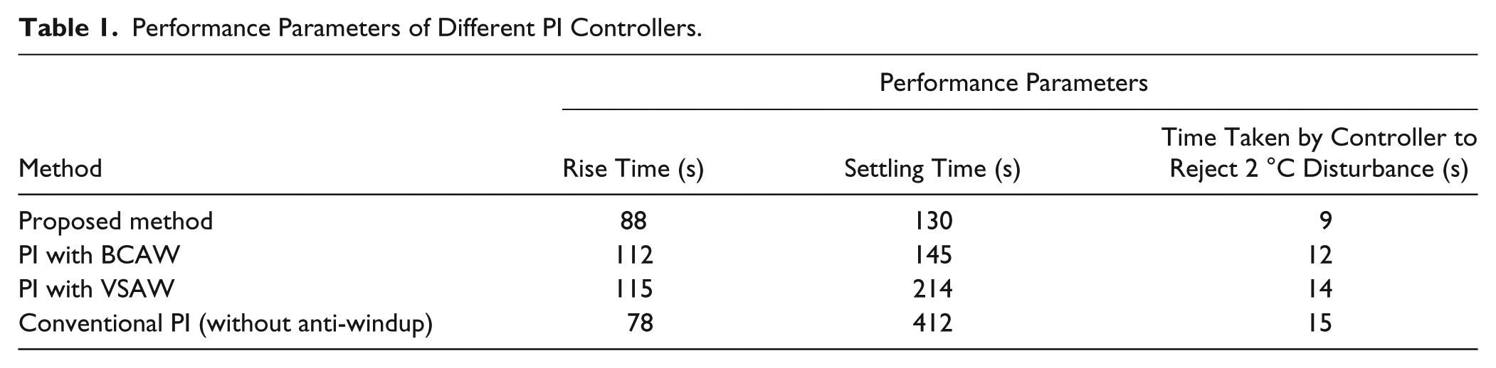
A general inference from the performance analysis of this control system design is that even though the heating element is intrinsically slow in response, the required time domain parameters could be engineered by designing an appropriate control system. The present work demonstrates that the PI controller with the proposed anti-windup structure serves the purpose of overcoming the intrinsic limitations of the heating pad and ensures that the design will be useful for any practical purpose of providing a stable working temperature. Very often, a proportional integral derivative (PID) controller16,17 has been used by control engineers for similar purposes of temperature regulation. As the heating rate of the heating pad used in this work is 0.5 °C/s—and hence for a system with such a slow response time—the derivative term in the PID controller is not regarded as essential.
In each step of the design reported in the present work, starting from system identification, deducing the second-order transfer function, and designing the control parameters for PI, the design is aimed at achieving the desired time domain specifications in stabilizing the temperature output of the heating pad, taking into account its experimentally measured heating characteristic, by using a proper choice of P and I parameters, as well as by designing an appropriate anti-windup structure. As evidenced in the performance evaluation, when the proposed system is operated after it has reached the steady-state temperature desired by the user, the system is stable and relatively unaffected by small environmental disturbances. Its ability to quickly come back to the stable temperature regime even in the presence of inevitable external disturbances is remarkable. Hence, it may be expected that the proposed control system is ideally suited for using the heating pad as a thermode in a CHEP stimulator, especially in situations where the heating pad makes and breaks contact with the skin of the subjects at repetitive intervals, which might cause momentary instabilities in the output temperature. Indeed, one of the essential requirements of the heat control system in this context is the ability of the controller in correcting such temperature fluctuations, if any, within the period of presentation of the next heat stimulus as dictated by the ITI (~10–20 s). The ability of the proposed system in handling this anticipated issue through fast rise and settling times, as well as CE, makes it useful for developing a custom-made CHEP stimulator design based on the novel PI controller with an anti-windup structure proposed in this work for conducting heat stimulus experiments in EEG. Besides, the realization of the control system in the digital domain makes it more user friendly by enabling a quick change in the values of various design parameters to suit varying needs that arise in the context of different applications. In EEG recordings with a commercial CHEP stimulator, the thermode will always be in contact with the skin, which might activate non-nociceptive fibers, and these non-nociceptive inputs might fall in CHEP origin. But, in the case of the proposed CHEP stimulator, as the thermode makes and breaks contact with the skin at regular intervals, the chance of activation of non-nociceptive fibers is likely to be less than that of a commercial CHEP system. This can be considered one of the major advantages of the proposed CHEP system. In addition, the cost involved in the development of the proposed CHEP system is nearly US$100, which is much cheaper compared with a commercial system. 5 The structure of the proposed CHEP system is simple and can be easily developed.
In summary, the discrete PI controller design presented here meets all the desired performance specifications, including the critical time domain specifications, such as reference tracking the set temperature and output disturbance rejection as envisaged by the user, especially in the context of a CHEP stimulator, and ensures a stable control of desired temperature as required in a number of applications.
Conclusion
We have presented a detailed design of a cost-effective PI control system with anti-windup to precisely set and maintain the temperature of a heating pad with reasonable response time, meeting the technical requirements of the CHEP stimulators. A detailed analysis of each of the constituent modules of the control system has been carried out, and by practically realizing the system, we have successfully demonstrated its performance. The proposed control system has been found to be suitable for designing a CHEP stimulator for neurological investigations.
Supplementary Material
Supplementary Material, Supplemental_by_fayaz,_et_al. – Design and Implementation of a Discrete-Time Proportional Integral (PI) Controller for the Temperature Control of a Heating Pad
Supplementary Material, Supplemental_by_fayaz,_et_al. for Design and Implementation of a Discrete-Time Proportional Integral (PI) Controller for the Temperature Control of a Heating Pad by Pathan Fayaz Khan, S. Sengottuvel, Rajesh Patel, K. Gireesan, R. Baskaran and Awadhesh Mani in SLAS Technology
Footnotes
Acknowledgements
The authors would like to thank Mr. Mohammed Danish, BE (Hons.), BITS, Pilani, for his valuable assistance during the hardware design of the controller. It is a pleasure to thank Dr. N. V. Chandra Shekar, Head, Condensed Matter Physics Division, and Dr. G. Amarendra, Director, Materials Science Group, Indira Gandhi Centre for Atomic Research, for their encouragement and support. The authors would also like to thank Mr. M. P. Janawadkar and Dr. T. S. Radhakrishnan for their suggestions for improving the manuscript.
Declaration of Conflicting Interests
The authors declared no potential conflicts of interest with respect to the research, authorship, and/or publication of this article.
Funding
The authors received no financial support for the research, authorship, and/or publication of this article.
References
Supplementary Material
Please find the following supplemental material available below.
For Open Access articles published under a Creative Commons License, all supplemental material carries the same license as the article it is associated with.
For non-Open Access articles published, all supplemental material carries a non-exclusive license, and permission requests for re-use of supplemental material or any part of supplemental material shall be sent directly to the copyright owner as specified in the copyright notice associated with the article.