
Abstract
We present methods to fabricate high-capacity redox electrodes using thick membrane or fiber casting of conjugated polymer solutions. Unlike common solution casting or printing methods used in current organic electronics, the presented techniques enable production of PEDOT:PSS electrodes with high charge capacity and the capability to operate under applied voltages greater than 100 V without electrochemical overoxidation. The electrodes are shown integrated into several electrokinetic components commonly used in automated bioprocess or bioassay workflows, including electrophoretic DNA separation and extraction, cellular electroporation/lysis, and electroosmotic pumping. Unlike current metal electrodes used in these applications, the high-capacity polymer electrodes are shown to function without electrolysis of solvent (i.e., without production of excess H+, OH–, and H2O2 by-products). In addition, each component fabricated using the electrodes is shown to have superior capabilities compared with those fabricated with common metal electrodes. These innovations in electrokinetics include a low-voltage/high-pressure electroosmotic pump, and a “flow battery” (in which electrochemical discharge is used to generate electroosmotic flow in the absence of an applied potential). The novel electrodes (and electrokinetic demonstrations) enable new applications of organic electronics within the biology, health care, and pharmaceutical fields.
Keywords
Introduction
Recent clinical and commercial advances in cell, gene, and immunotherapies have caused a renewed interest in laboratory automation with a focus on simplification of production workflows and improved analytical testing and quality control.1–11 To achieve this, manufacturers have sought to develop facilities capable of continuous processing in fully closed and disposable (or single-use) systems, to eliminate down time or waste associated with traditional batch reactor systems.1,2,9,10 Electrokinetic components (i.e., components that control electric currents within heterogenous biological fluids) play important roles in many bioprocess and bioassay workflows, including cell lysis (for collection and processing of intracellular proteins or molecules), cell electroporation (for cell transfection in cell therapy workflows), electrophoretic separations (for sorting and purification of biomolecules), and electroosmotic flow control (for moving fluids, cells, and particles).12–16 However, the metal electrodes commonly used to maintain electrical current within biological fluids and perform these electrokinetic operations have well-known limitations.17–19 Most of these electrodes employ electrolysis for generating current and produce excess H+ and OH–, which can negatively affect cells and biomolecules within the fluid. In addition, gas products (O2 and H2) produced during electrolysis may block electrode access to the biological fluid, creating electrical shorts during operation. These problems have been addressed in the past by using large reservoirs of fluid around electrodes or adding chemical buffers to minimize the effect of the by-products; however, these add complexity to both the device (i.e., increased fabrication costs and fluid system complexity) and the biological fluid (i.e., the potential to affect cells and/or biomolecules within the buffered solution). With renewed interest in creating simple closed and single-use bioprocess systems, it is important that these long-standing problems are addressed.
Organic electronics is an active area of materials science research that has recently expanded beyond traditional use in transistors and light-emitting diodes to devices and applications in chemistry and biology.20–22 Poly(3,4ethylenedioxythiophene) polystyrene sulfonate (PEDOT:PSS) is one pi-conjugated polymer that is both conductive and electrochemically active, enabling both coupling to metal contacts (for application of an applied voltage from a power source) and liquid solutions (for electron-to-ion charge transfer based on solid-phase redox reactions). 23 Commercial PEDOT:PSS solutions contain a mixture of doped (oxidized and positively charged) and undoped (reduced, neutral) PEDOT polymer chains and can be used as both anode and cathode material for ionic current injection into biological solutions. Recently, this phenomenon has been used to create polymeric neural interfaces and implants,24,25 bioactive cell and tissue scaffold materials, 26 and artificial chemical/biological synapses.27,28 However, the capability of pi-conjugated electrodes to eliminate electrolysis and be used in this capacity is limited. These materials are susceptible to overoxidation when driven by potentials greater than 1 V (in the presence of oxygen), breaking the conjugation within the polymer chain and decreasing conductivity. Therefore, the size of the electrode itself (and mass of doped and undoped material within it) dictates the maximum electrochemical capacity of the system. For these reasons, applications of redox polymers (such as PEDOT:PSS) in biological research has been relegated to low-voltage/low-current applications with few exceptions, decreasing the potential for use in bioprocess/bioassay applications such as electroporation and electrokinetic separations.
Herein, we test two different fabrication methods for creating high-capacity (i.e., high-mass) PEDOT:PSS electrodes (i.e., thick membrane impregnation and fiber casting) and test their utility in several common steps in bioprocess/bioassay workflows, including DNA separation/extraction, mammalian cell lysis, electroosmotic pumping, and fluidic valving and control. The electrodes produced are shown to enable flexible packaging schemes, including lamination within disposable fluidic cassette and molding into common fluidic screw-in connectors. Within the DNA separation/extraction tests, the PEDOT:PSS electrodes are shown to drive high-voltage electrophoretic extraction and collection of DNA from common cellulose storage cards within minutes, compared with the typical half-hour times typically required. 29 In addition, the polymer electrodes are tested for improved bioassay compatibility (enabling extraction of PCR amplifiable DNA with minimum oxidative damage) compared with standard metal electrodes. The cell lysis experiments presented show the capability of the polymer electrodes to be used in a simple DC-voltage, flow-through lysis device, maintaining voltage gradients greater than 2000 V/cm across the cells. Within the electroosmotic pump (EOP) experiments, the capability of the polymer electrodes to be laminated into simple plastic structures enables the fabrication of a new type of alternating electric field EOP, capable of running at high back-pressures using low driving voltages. Finally, the polymer electrodes within the new EOP are used to introduce a new type of electrokinetic device (the “flow battery”). In this new device, the polymer electrodes are shown to be capable of driving electroosmotic flow without direct connection to a battery (instead, based on stored electrochemical charge). These results demonstrate that with proper electrode design and fabrication schemes the field of organic electrodes can be applied successfully to bioprocess and bioassay applications and achieve performance superior to the current metal alternatives.
Materials and Methods
Casting PEDOT:PSS Electrode Materials
High-capacity PEDOT:PSS electrodes were fabricated using two methods. In the first method (i.e., method 1), PEDOT:PSS emulsion (poly(3,4-ethylenedioxythiophene)-poly(styrenesulfonate), 1.3 weight percent dispersion in water, Sigma-Aldrich 483095) was cast across sheets of cellulose paper (Whatman 31 ETF). The cellulose paper was first cut into square sheets (6.35 cm sides), and the squares were mounted in an aluminum frame and positioned on a heating surface. The heating surface was maintained at 130 °C, and 2 mL of the PEDOT:PSS solution was evenly applied to the surface of the paper and left to dry for 15 min. The frame was then turned over, and another 2 mL of the polymer solution was cast on the opposite side and dried. This process was repeated three times for each side of the 31 ETF sheets. Once dried, the paper was covered in 2 mL of 80% EtOH solution and heated for an additional 30 min at 130 °C. The dried PEDOT:PSS-impregnated paper was then removed from the heating surface and frame and incubated in 0.25 M MgSO4 for 1 h for additional cross-linking. This step was repeated for an additional hour to provide two separate cross-linking incubation periods. The PEDOT:PSS paper samples were then placed into an oven for final drying before further processing or packaging within the electrokinetic devices.
A second method (i.e., method 2) to produce high-capacity PEDOT:PSS electrodes used a slurry of cellulose fiber/PEDOT:PSS in place of the premade cellulose sheet. In this method, cellulose fibers were first created using a ball milling process, in which pieces of Whatman 31 ETF were placed in a 4 L glass jar. The jar was filled with distilled water and glass beads (diameter = 0.5 mm). The jar was sealed, placed on a lab roller, and mixed for 24 to 48 h, allowing the cellulose paper to break down into fibers. The fibers were then isolated through a fritted glass filter by vacuum filtration, washed in distilled water, and air dried. Following the wash process, 1.5 g of dry cellulose fibers was added to 15 g of Clevios PH 100 PEDOT:PSS solution and mixed for 15 min. A glass ring (diameter = 6.4 cm) was then placed on a clean surface, and 11.1 g of the fiber/PEDOT:PSS mixture was poured into the ring. The cast solution was incubated for 3 d to allow for water evaporation and formation of a thick PEDOT:PSS/cellulose film. The film was then removed from the glass ring and cross-linked using the MgSO4 step described above. The final cross-linked films were incubated in an oven at 60 °C for 1 h and stored in sealed air-tight glass vessels before further processing or packaging within the electrokinetic devices.
Assembly of PEDOT:PSS/Cellulose Materials into Electrodes
Two different methods were used to assemble the PEDOT:PSS/cellulose materials into electrodes (each being used for specific device assemblies and electrokinetic applications discussed below). As shown in Figure 1A and B , the intact PEDOT:PSS cellulose sheets (method 1) were cut in 10 mm disks for lamination with thin copper contacts (shaped in a circle to provide electrical contact to the polymer disk around the entire perimeter). The adhesive Kapton film used to laminated these two parts together (i.e. the PEDOT:PSS/cellulose disc and metal contact) was compressed, leaving only the interior (polymer only) section exposed to liquid during use within electrokinetic devices. The copper contact enabled attachment to the leads of constant voltage or current power supplies, electronic conduction into the polymer disk, and finally ion conduction from the center of the polymer disk to the liquid within the device. Figure 1B shows an example of use in assembly of an electroosmotic pump, in which two PEDOT:PSS electrodes are placed on either side of an anodized alumina nanoporous membrane (Anodisc; GE Healthcare, Chicago, IL) and laminated into an EOP assembly using the adhesive Kapton film. The design is simple and allows integration of the pump into standard fluid flow cells (as shown below).
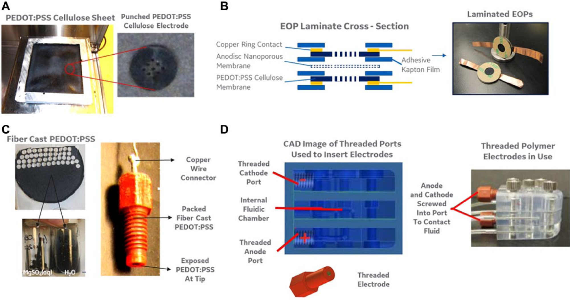
PEDOT:PSS components and device fabrication methods. (
The second assembly method for electrodes used commercially available threaded fluidic connectors (Upchurch flangeless, PEEK fittings) as a mold for the PEDOT:PSS/cellulose slurry described above (method 2). As shown in Figure 1C , the internal opening within the fluidic connector was filled with the dried PEDOT:PSS/cellulose slurry, and a small metal rod was used to press the polymer/cellulose material into the connector, resulting in a tightly packed polymer electrode core. A copper wire was placed within the internal opening of the fluidic connector at the distal end, which served as the contact to connect to the leads of the external power supplies. As shown in Figure 1D , the threaded fitting was assembled into electrokinetic devices by fabricating threaded ports into the polymer fluidic device. The surface of the screw-in electrodes was designed to reach the fluid channel within the device (with the electrodes wetting during priming and filling of the devices with water or buffer). Like the laminated electrode assemblies described above, the dry copper/PEDOT interface within the fitting served to enable electronic conduction into the polymer, whereas the liquid/PEDOT interface within the flow channel enabled ion conduction from electrode to liquid/buffer. These two assembly techniques described enabled electrode integration into many different types of fluid flow channels for use in bioprocess and bioassay applications, including rapid prototyped or injection-molded plastic flow cells, laminated microfluidic components, and static fluid reservoirs (application in these devices is discussed below).
Microfluidic Devices for Electrical Cell Lysis Experiments
Figure 2A shows the threaded polymer electrodes interfaced within a microfluidic flow cell designed for high-throughput cell lysis. The microfluidic channel was fabricated using a three-layer lamination-based technique. The base and top layer were constructed from a 0.005 inch thick polyimide sheet (Kapton HN; DuPont Electronic Technologies, Circleville, OH). The inner layer of Dupont Pyralux LF0111 Bondply was machined using a 355 nm ultraviolet wavelength laser (ESI 5200; Electro Scientific Industries, Portland, OR). The laser-cut profile included a microfluidic channel located between inlet and outlet ports for injection of mammalian cell suspensions ( Fig. 2B, C ). Two other ports were built into the microfluidic channel to allow access to two threaded polymer electrodes. The microchannel was machined to include a narrow fluidic constriction at the center of the device, in order to provide a high-resistance element that would isolate most of the voltage drop applied from electrode 1 to electrode 2 in an 80 µm segment of the channel. Cells that traverse the fluidic channel are guided into this area of high electric field strength for rapid electrical lysis. For the experiment presented herein, a rapid prototyped part (Protolabs, Maple Plain, MN) was designed with a needle inlet and outlet port for the introduction and collection of the cell suspensions and built-in threaded ports that accepted the PEDOT:PSS electrodes built into the Upchurch connectors (as described above). Prior to introducing the threaded electrodes, a 4 mm Ultracel 3Kda regenerated cellulose ultrafiltration disc (catalog No. PLBC04310; Millipore Corp., Billerica, MA) was placed into the electrode port. This disc provided an ion-permeable (but large-biomolecule-impermeable) barrier between the fluidic circuit and the electrode ports. A syringe pump was used to control flow rates through the electrical lysis device, where the flow rate controlled both the rate of cells entering the high electrical field constriction and the width of the electric field pulse experienced by the cell ( Fig. 2D ). Prior to use, the device was primed with low-conductivity buffer, consisting of 10 mM KH2PO4, 1 mM MgCl2, and 250 mM sucrose. This priming step ensured the elimination of any bubbles or air pockets within both the microchannel and the threaded electrode ports and enabled passage of ionic current across the regenerated cellulose barrier.
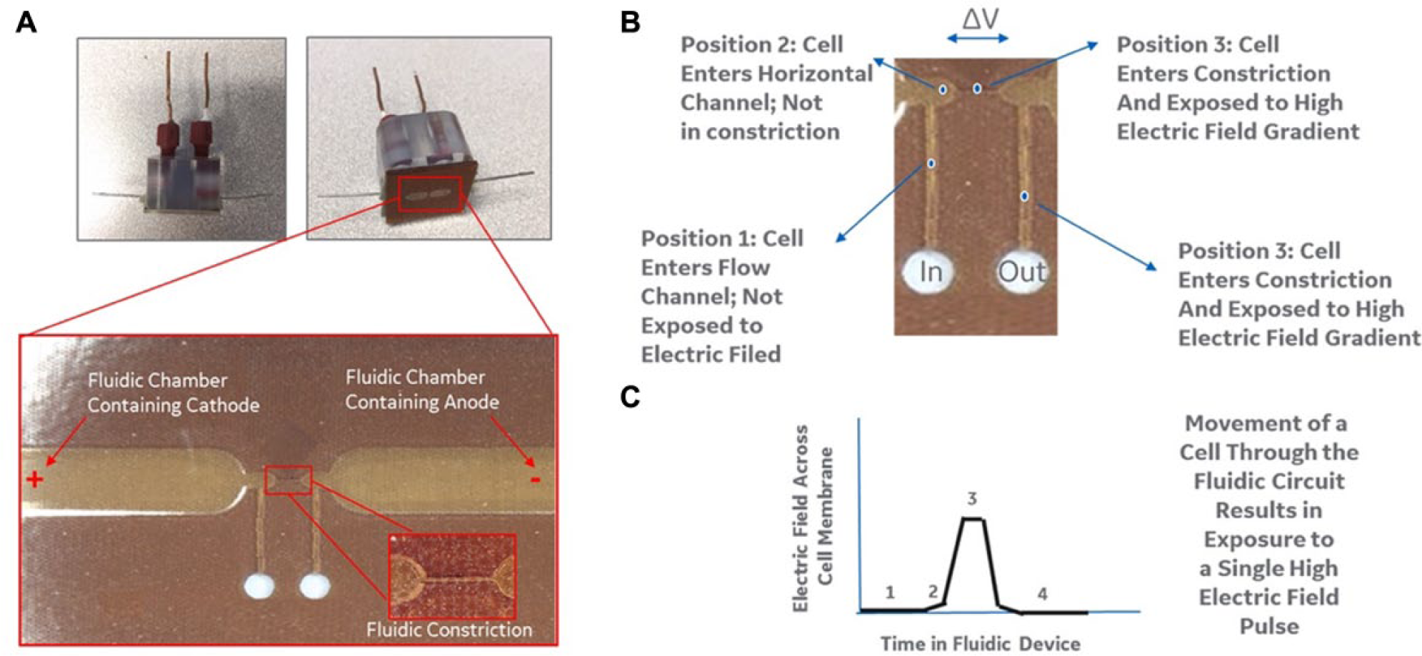
Electrical cell lysis device. (
Fluidic Chambers for Rapid DNA Extraction from Nucleic Acid Storage Cards
Figure 3 shows a second device that was built using the threaded polymer electrode interface. In this device, a rapid prototyped part was constructed that enabled loading of an FTA® nucleic acid storage card and placement of PEDOT:PSS electrodes directly above or below the card. Once loaded, the fluidic channel contained within the rapid prototyped device (containing the FTA card) was loaded with a DNA extraction buffer (Tris-HCl). An electric field was then applied across the card to provide an electrophoretic force on nucleic acid within the card. The regenerated cellulose barrier was again used between the fluidic channel and the electrode port, providing a surface for nucleic acid accumulation (without loss into the electrode material). After application of the electric field, additional DNA extraction buffer was pulsed through the device using a syringe pump, and the electrophoretic extracted DNA was collected. The collection times and efficiencies were compared with the standard extraction technique, which is to simply incubate the FTA in extraction buffer for 0.5 to 1 h and allow passive diffusion of the nucleic acids off of the storage card.
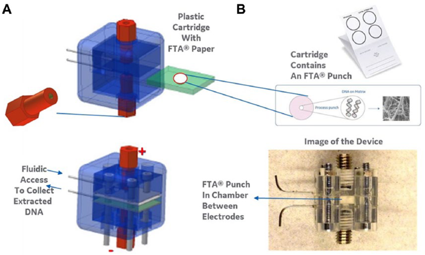
Device for rapid elution of DNA. (
Alternating Layer Electroosmotic Pumps for Low-Voltage, High-Pressure Operation
Figure 4A depicts a new type of multilayered EOP that was fabricated using the PEDOT:PSS cellulose sheet electrodes described above. In a single-layer pump, a pair of the electrodes was used on either side of a nanoporous anodized alumina membrane (Whatman Anodisc, 25 mm, 0.02 mm pores; GE Healthcare), one as an anode and one as a cathode (as shown above). This type of electrode/Anodisc/electrode assembly was placed in a fluidic channel (integrated EOPs shown in Fig. 4B ) and primed with deionized water or buffer. As with previous EOPs, application of an electric field across the pores within the Anodisc produced an electrokinetic force on the charged ions adjacent to the charged alumina surface, which produced a fluid flow in the direction of the applied field. Within the nanopores, the viscosity of the liquid is sufficient to cause fluid movement, and fluid flow in each nanopore within the disc contributes to bulk movement of liquid within the larger fluidic channel. As the Anodisc is thin (100 µm), a large electric field is applied across the nanopores using a relatively low applied voltage between the PEDOT:PSS electrodes. However, in traditional EOPs, any back-pressure applied to the fluidic circuit would act in opposition to the electroosmotic flow and act to stall the pump. Previous studies have shown that increased pumping pressure can be realized by increasing the overall thickness of the nanoporous material (i.e., increasing the internal fluidic resistance of the pump using a ceramic frit or other material). However, this increase in thickness typically requires an increase in the applied electric field (as the spacing between the electrodes must be increased to accommodate the thicker nanoporous material).30,31 For these reasons, pumps with practical pumping pressure typically require application of electric fields greater than 500 V, maintained by electrolytic reactions between two metal electrodes producing chemical and gaseous by-products.
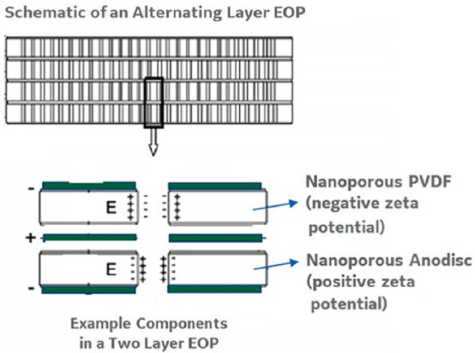
Electroosmotic pump (EOP) assembly. A schematic of the electrode and pumping layers within a novel multilayer EOP. In this concept, the pumping pressure is increased by adding additional nanoporous electroosmotic discs to the pump (compared with the single-layer pump shown in Fig. 1 ). As shown, the PEDOT:PSS electrodes are layered in between each layer of the electroosmotic disc; this allows continued use of low applied voltages (as the electrode spacing remains the same as the single-layer EOP). However, if only the Anodisc (positive zeta potential electroosmotic disc) was used, then electroosmotic flow would occur in reverse directions in each successive layer (i.e., always moving toward the anode). Instead, the team has used a negative zeta potential polyvinylidene fluoride (PVDF) membrane in each successive layer. Using this arrangement, the electric field direction is reversed in each layer of the pump, but the direction of flow remains the same (i.e., toward the cathode in the PVDF layer and toward the anode in the Anodisc layers). This novel configuration allows increased pumping pressure without the usual need to increase applied voltage on the pump (in order to pump across increasingly thick layers of electroosmotic material).
The new PEDOT:PSS cellulose sheet electrodes were used to redesign high-pressure pumps and enable operation at high back pressure with low operating voltages. Figure 4A shows the design of these novel EOPs in which the polymer electrodes were alternatively placed between the positive zeta charge Anodisc and the negative zeta charge polyvinylidene fluoride (PVDF) nanoporous membrane (durapore membranes; Millipore). In this configuration, ions within the Anodisc nanopores were driven toward the cathode (positioned at the output of that pumping layer), whereas ions within PVDF membrane nanopores were driven toward the anode during application of an electric field (using the alternating cathodic/anodic PEDOT:PSS electrodes). Thus, each successive layer pumped the fluid using positive- or negative-charged ions successively, and additional layers could be added to the pump by simply placing on another successive layer of Anodisc or PVDF membrane. With this novel alternating design, additional layers (and higher pumping pressure) do not require higher applied voltages (as each pump layer has its own anode and cathode placed directly in contact).
Flow Batteries: Precharging Polymer Electrodes in EOPs for Flow upon Discharge
In addition to use as anode and cathode materials in driving electrokinetic devices, PEDOT:PSS has been used in fabrication of type I capacitors (i.e., the anode and cathode are made from the same material). The capacitance formed in the PEDOT:PSS electrolyte interface can be understood by envisioning the PEDOT:PSS electrode as a degenerately doped p-type semiconductor (i.e., holes on the PEDOT are compensated by sulfonate anions within the PSS). When a voltage is applied across the material, de-doping occurs, in which cations are injected into the polymer electrode and holes are extracted through the metal contact on the other side of the polymer. The overall capacitance of any PEDOT:PSS electrode is also dependent on the overall volume of the polymer material within the electrode (as the electrode contains a finite number of sulfonate anion/hole pairs, and injected cations can replace these sites only up to the material’s hole density). Previously, these properties of PEDOT:PSS have been used to temporarily store electric charge and discharge in the form of an electrical current. Figure 5 shows a schematic diagram of a new use of this property in precharging an EOP and using the stored energy to discharge in the form of electroosmotic flow, thus producing a flow battery, in which fluid flow is generated in the absence of a traditional battery or applied electric field.
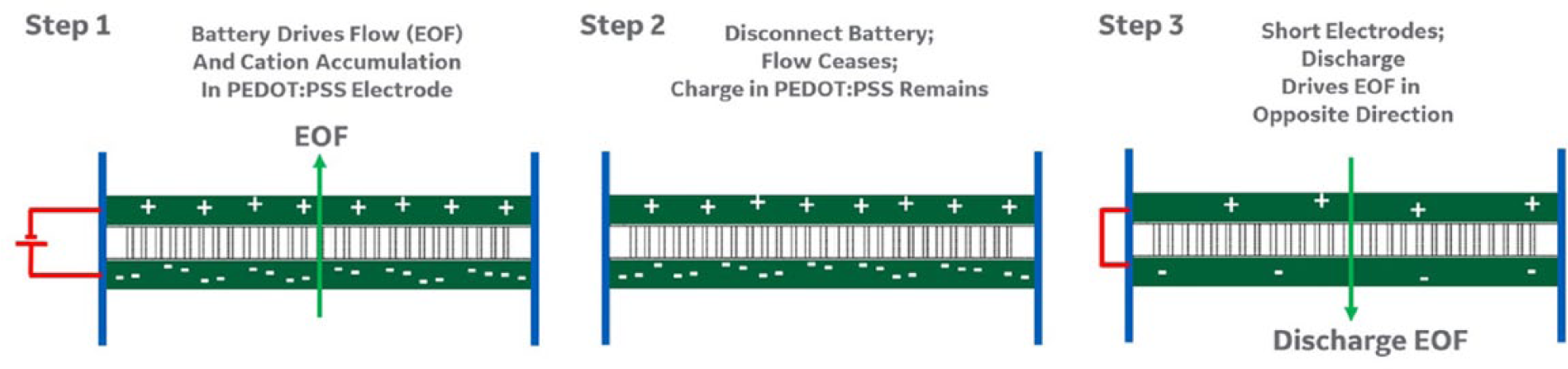
Electroosmotic pump (EOP) actuation sequence. A schematic outlining the steps required to run a flow battery using a single-layer EOP. Step 1: The pump is first run in the forward direction using a battery that acts to provide electroosmotic flow (EOF) and in doing so charges the PEDOT:PSS electrodes. Step 2: The electrical contact to the battery is removed and the charge built in step 1 is stored in the electrode of the pump. Step 3: The anode and cathode within the pump are shorted using a metal wire (across the contacts of each electrode), which causes the electrochemical charge stored in the pump to discharge. This original charge on the electrodes acts as an applied electric field across the pump, and the discharge causes EOF in the opposite direction (of the original EOF during the initial charging step).
Integrated EOPs for Remote Operation of Fluidic Valves and Controls
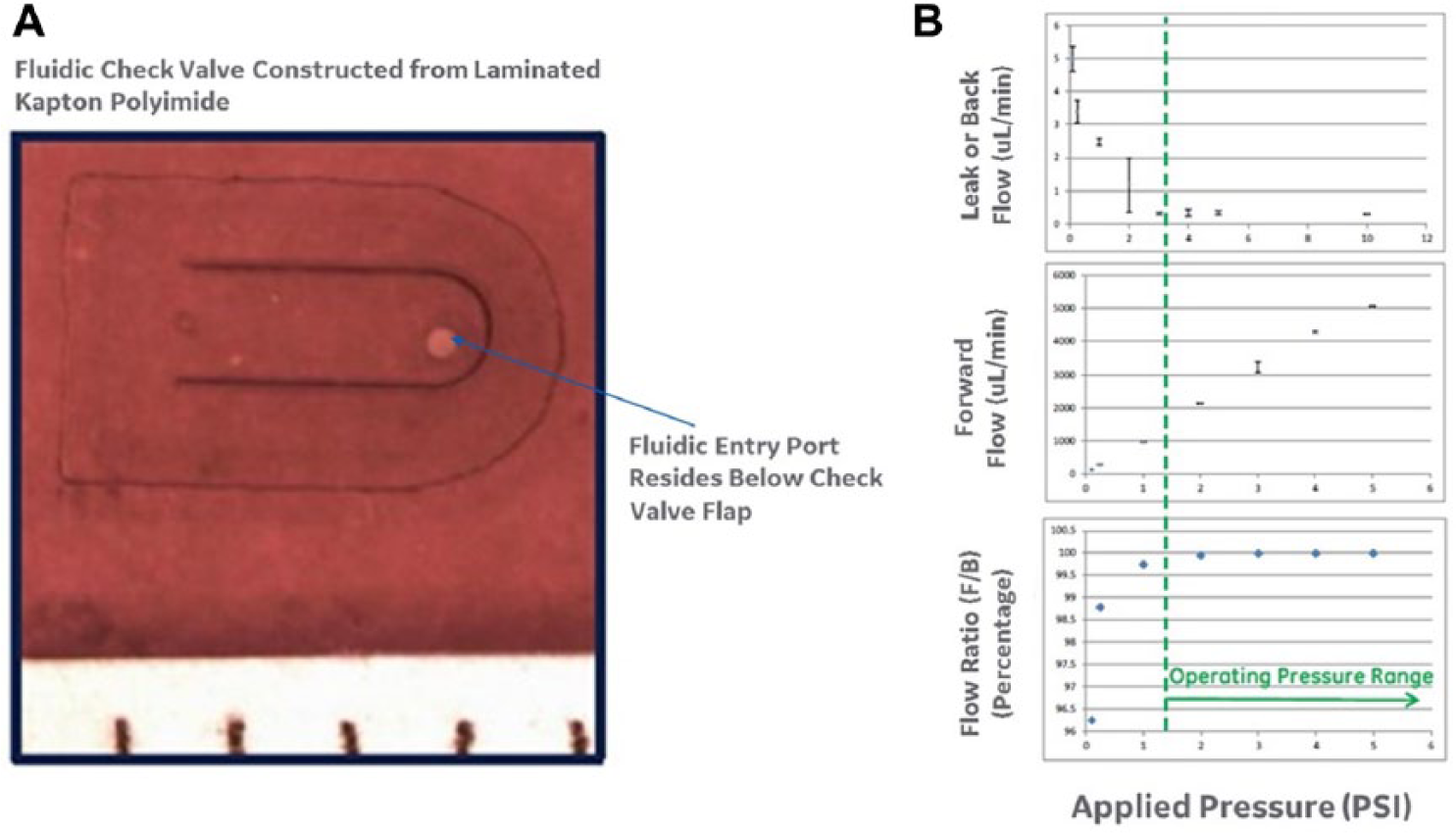
Finally, the high-pressure, low-voltage EOPs were interfaced with simple fluidic check valves and used to generate the pressure required to actuate the control structures. Currently, a variety of external pressure sources are used to control fluidic valves and control structures in bioprocess and bioassay applications.32,33 These control components are important to time and manage the injection of reagents into a variety of biological and chemical reactions. However, these external controls make the systems complex (requiring tubing connections and wires for every valve built into the system). Application of the new low-voltage, high–back-pressure EOPs to directly actuate valves within fluidic systems eliminates the need for tubing interfaces to external pressure sources and provides operating parameters that may be driven using common batteries (and low-voltage power sources). A one-way flow-check valve was designed by constructing a flexible flap above the flow port. The flap was laser machined from 0.001 inch thick Kapton HN polyimide, the port below was ablated in 0.005 inch Kapton HN material, and the two layers were bonded through a lamination process with the use of an intermediary adhesive layer of Pyralux LF0100. In use, fluid flow through the port structure would deflect the check valve flap and allow flow through the valve, whereas reverse flow would force the flap back in plane, sealing the port and restricting flow in the opposite direction.
Cell Culture, Quantification, and Analysis
CHO cells were cultured using standard methods and expanded to achieve cell densities of 1 million cells/mL prior to use in the electrical lysis experiments. Cell density was measured using a Nucleocounter NC-100 automated cell counter (Chemometic, Allerod, Denmark), and electrical lysis was measured using the viability standard provided in the commercial system (and measuring the percentage of viable cells before and after flow through the electrical lysis device). Lysis efficiency was reported as the percentage of total viable cells that were lysed into exposed nuclei.
DNA Quantification and Analysis
Commercially available genomic DNA (Thermo Fisher Scientific, Waltham, MA) was applied to FTA cards (GE Healthcare) at known concentrations for all DNA extraction studies. The quantity of DNA added to the card and then extracted using the electrical extraction procedure was measured using a picogreen DNA quantification kit (Thermo Fisher Scientific) and a standard multiwell spectrophotometer. DNA extraction yield was reported as the mass of DNA applied onto the FTA cards versus that which was recovered in the eluent after the electrical extraction procedure described above.
Flow Measurement and Pump Characterization
In all EOP and pump experiments, a flow sensor (optical flow sensor; Sensirion, Westlake Village, CA) was attached to the outlet of the EOP and filled during the priming procedure for the pump described above. After fluid priming, the EOP sensor system was allowed 10 min to ensure pressure equilibration across the system, and the sensor was then turned on to monitor the fluid flow produced by applying a voltage to the EOP. The sensor was calibrated (per the manufacturer’s instructions) to measure fluid flow between 0 and 500 µL/min. The pumping pressure of the EOP assemblies was measured by placing a positive-pressure source at the output of the pump (i.e., a measured height of water head) to control the pressure-resisting fluid movement in the EOP outlet tube. The pump stall pressure was measured as the applied back pressure that returned the EOP to zero flow (using a ruler to measure head height), despite an actively applied electric field.
Results
Applications in High-Throughput Cell Electrolysis
Figure 6A
depicts the results of operating the electrical lysis device across a range of operating voltages, compared with a standard chemical lysis procedure. In each experiment, 400 µL of sample was pumped through the device at 200 µL/min at a cell density of 1.5 × 10⁶ cells/mL. The results show that the percentage of lysed cells increases with applied voltage and that the PEDOT:PSS electrode assembly maintains adequate capacity to drive the DC field for operation times that enable passage of millions of cells through the device. In addition to increasing applied voltage to achieve higher lysis efficiency, the high flow speeds of the system can be leveraged (as shown in
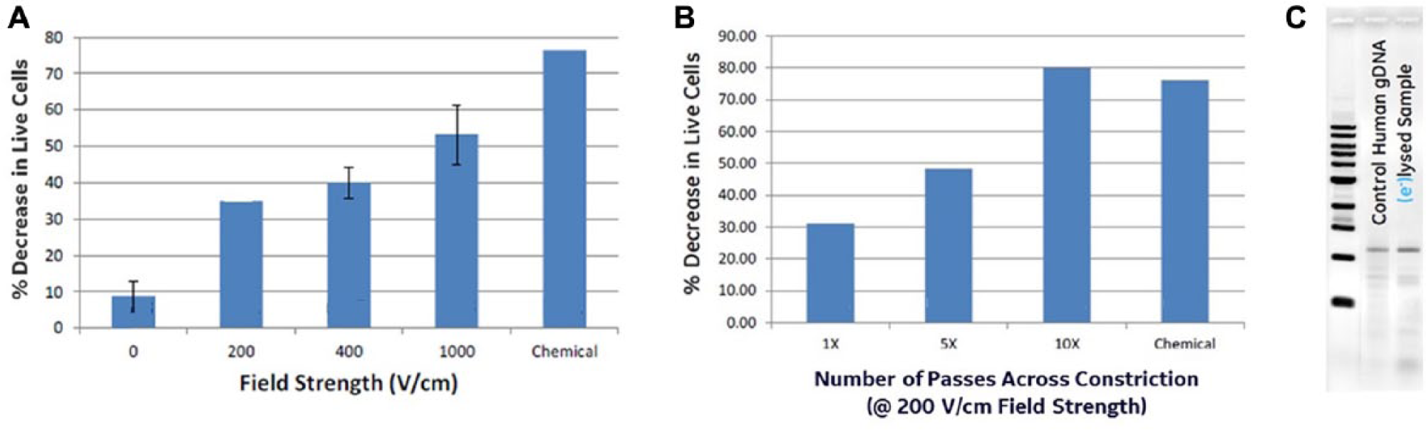
Electrical cell lysis. (
Applications in Rapid DNA Extraction from Paper Storage Cards
Figure 7 depicts the results of operating the DNA extraction device on FTA cards that were preloaded with 1 µg of genomic DNA and fully dried (as per the manufacturer’s suggestion for storing DNA on the card). Electrical extraction was performed by applying 25 V across the FTA card for 60 s, starting flow at 100 µL/min (for a total of 100 µL), and collecting the eluate in a centrifuge tube. During fluid flow, two electrical pulses were applied in the reverse direction (–25 V), to drive DNA off the regenerated cellulose barrier between the fluid compartment and the electrode port. Figure 7B shows that an equivalent amount of DNA was recovered from the storage card using the 2 min electrical lysis procedure and the standard 1 h buffer incubation process recommended by the manufacturer, 29 providing a new rapid method of extraction for downstream processing. Figure 7C quantifies this effect by running extraction buffer through the device with and without application of the electric field. The regenerated cellulose barrier between the fluid and electrode chambers in these experiments underwent an additional coating procedure using a Nafion solution and then drying. Downstream DNA amplification was used to evaluate the extent of DNA damage due to oxidation caused by contact with the electrodes. Figure 7D shows that when run at field strengths of 500 V/m, the use of standard platinum electrodes in the system (to replace the treated PEDOT:PSS/cellulose electrodes) resulted in significant oxidative damage to the extracted DNA and PCR failure, whereas use of the PEDOT:PSS electrode resulted in quality extracted DNA. However, this DNA quality was dependent of the PEDOT:PSS electrode undergoing the Mg cross-linking and Nafion coating treatment discussed above. The figure shows that while operating at these high electric field strengths, only the cross-linked and coated PEDOT:PSS electrodes enable postextraction DNA amplification, but at the lower operation voltage (100 V/m), both the platinum and cross-linked PEDOT:PSS electrodes enable downstream DNA amplification.
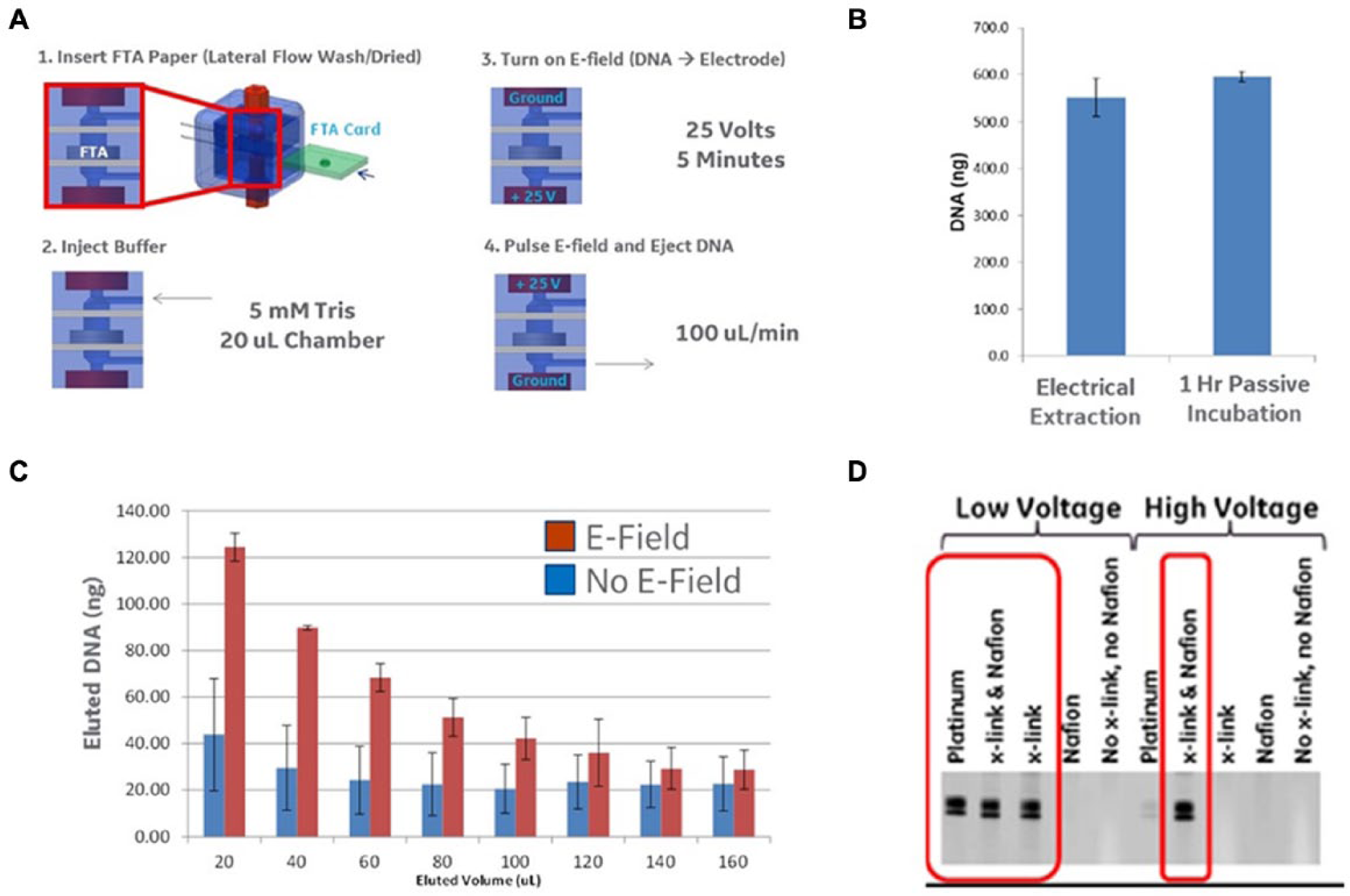
Electrical elution of DNA. (
Applications in Low-Voltage, High-Pressure EOPs
Figure 8A shows that the flow rates from single-layer EOPs (assembled using one 8 mm Anodisc and a pair of PEDOT:PSS cellulose sheet electrodes) were adequately measured using the flow sensors previously described and that flow was rapidly established upon applying a voltage to the pump assembly. Figure 8B demonstrates that use of the PEDOT:PSS electrodes enabled flow rates greater than 100 µL/min at applied voltages of less than 50 V and maintenance of a linear applied voltage versus flow curve over the entire measured range. Figure 8C shows that replacing the PEDOT:PSS electrodes with a platinum alternative (20 µm pore platinum mesh) resulted in much lower flow rates at a given applied voltage and a nonlinear relationship between voltage and flow at voltage greater than 30 V. Figure 8D shows that the addition of a second/alternating EOP layer (using the PVDF membrane and an additional PEDOT:PSS electrode as described above) doubles the pumping pressure of the EOP, and building the pump with four alternating layers provides the expected 4× increase in pumping pressure. The pumping pressure was measured by running the EOP into a fluid channel connected to a water reservoir and measuring the output of the pump against a known head of water (the zero-flow position is equivalent to the output pressure for each pump).
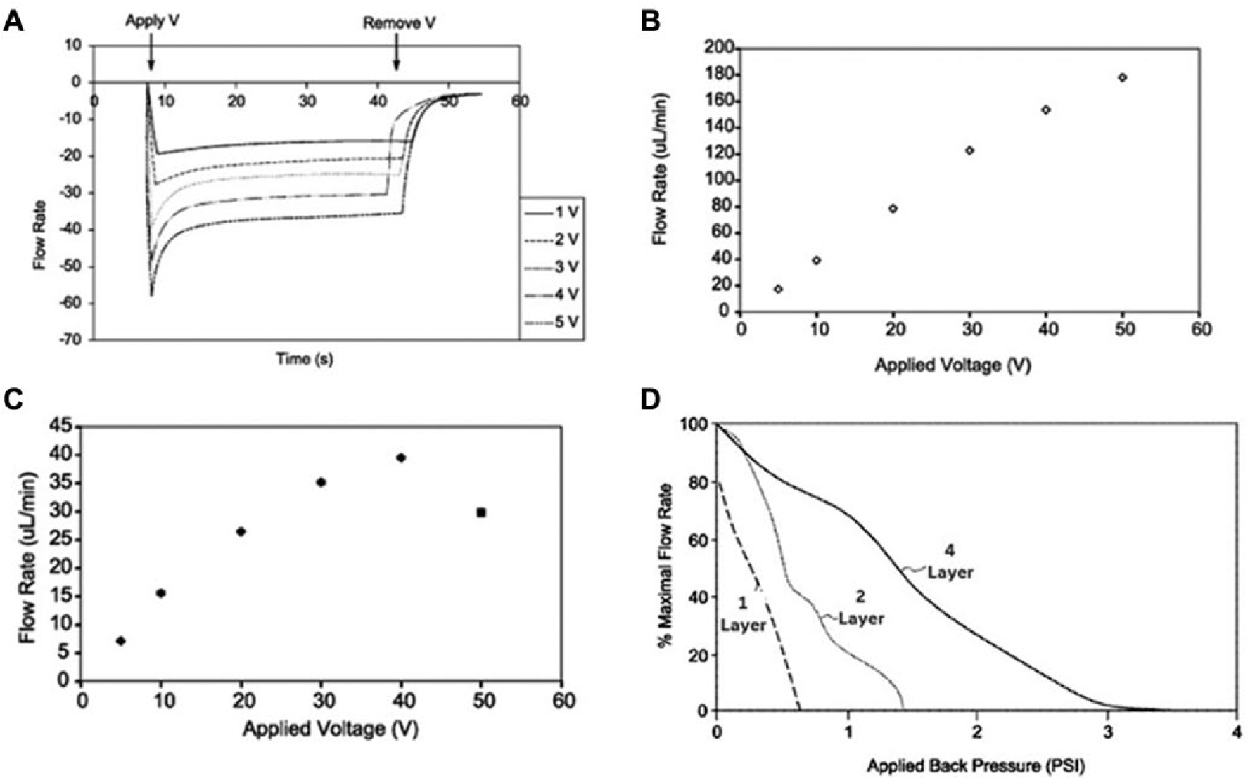
Flow rates of electroosmotic pumps (EOPs). (
Applications in Flow Batteries: Electroosmotic Flow through Electrochemical Discharge
Figure 9A shows the flow generated by first charging a single-layer Anodisc EOP at 10 V for 10 min versus 20 s, removing the power source, waiting for 10 min with the electrode contacts in an electrically open state, and then shorting the anode and cathode contacts together to allow electrochemical discharge. As shown, the energy stored within the PEDOT:PSS electrodes was capable of driving fluid flow within the EOP for more than 50 min (after the 10 min charge) with a peak flow rate of ~5 µL/min and an average flow rate of 0.5 µL/min. However, the shorter 30 s charge enabled fluid flow for a much shorter time (less than 5 min). To further demonstrate that the measured fluid flow (after shorting the anode and cathode) is due to electrochemical discharge through the EOP structure, the diameter of the electrode/Anodisc pump was changed from 10 mm to 5 mm, and the peak flow rate was measured for each size. As shown in Figure 9B , the flow rate dropped for the smaller pump, demonstrating that the lower capacity/lower surface area electrode provided less of an electrochemical potential for electroosmotic flow. Finally, the ability of the EOP to function under electrochemical discharge should be dependent on the electrical path (i.e., short) between the precharged anode and cathode. To test this, the electrical connection between the anode and cathode of a precharged (10 min at 10 V) EOP was broken at the ~17 min time point during discharge. As shown in Figure 9C , upon opening the electrical circuit, the fluid movement is discontinued, and reclosing the circuit (i.e., shorting the anode and cathode leads) results in reestablishment of electroosmotic flow, thus demonstrating that the EOP is being primarily driven by discharge from the precharged PEDOT:PSS electrodes.
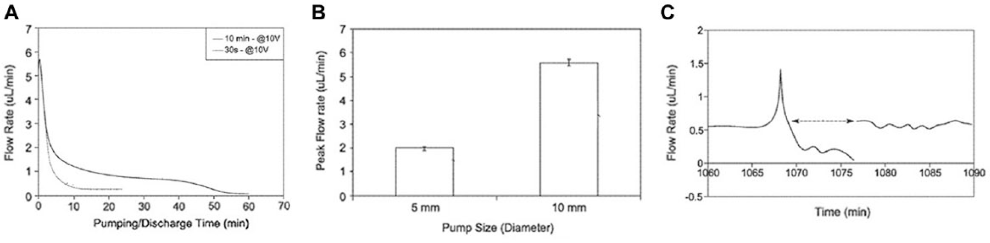
Characterization of electroosmotic pump (EOP) flow rates. (
Applications in Low-Voltage, Small-Footprint Actuation of Microfluidic Valves
Figure 10 shows the fluid flow output from a simple fluid channel containing the check valve shown. It was assembled and operated using the flow output from an alternating five-layer EOP. The EOP output pressure was monitored without the check valve and achieved output pressure greater than 350 cmH2O (i.e., 5 PSI). The check valve was then placed in series with the EOP, and the output pressure required to close the check valve was monitored by measuring the fluid flow through the check valve in both the open and closed flow direction (using the flow sensor described above). The simplest designed check valve (horizontal flap valve structure) was completely closed at pressures exceeding 4 PSI, demonstrating that the low-voltage, high-pressure EOPs can be applied for fluidic valving and control in the absence of external pressure or high-voltage power supplies.
Design of fluidic check valve and performance evaluation. (
Discussion
The fabrication methods discussed herein show that commercial redox polymer solutions can be processed in high-capacity electrodes that enable application in high-voltage/high-pressure electrokinetic component operation. These electrodes have been shown to function in several applications relevant to bioprocess and bioassay workflows, including DNA electrophoresis/extraction,19,29 cell electrical lysis,12–14 electroosmotic pumping, 34 and self-contained fluidic and valve control. 33 These accomplishments will enable near-term replacement of standard metal electrodes within diagnostic and therapeutic manufacturing workflows using methods compatible with production of fully-closed and disposable systems.1,9,13,17 Beyond this increased flexibility in fabrication, manufacturing, and integration, the novel electrodes were shown to improve the function of several of the electrokinetic components tested, including increased compatibility with DNA amplification in high-voltage applications,15,19 increased electroosmotic pumping pressure,30,31,34 and direct integration of battery-operated EOPs for self-contained fluidic valving and control32,33 (compared with the external tubes and pressure/power sources currently required). Finally, the use of the redox polymer electrodes led to a new discovery, as the EOPs built with the novel electrodes were precharged with an electrochemical potential that was later used to run the pump in the absence of an applied voltage. Future work using these electrodes will include examples of use directly within cell manufacturing1–11 (i.e., rapid electroporation for transfection in CAR T cell workflows), forensic29,35 (i.e., rapid DNA extraction and processing from FTA and other nucleic acid storage and collection devices), and research19,36,37 (i.e., disposable electrophoretic or microfluidic systems) workflows.
Footnotes
Acknowledgements
Parts of the technology developed in this article were prepared with the support of the U.S. DTRA under award No. HDTRA110C0033. Portions of the technology were also further developed under DARPA W911NF-14-2-0020, New Tools for Comparative Systems Biology of Threat Agent Action Mechanisms. However, any opinions, findings, conclusions, or other recommendations expressed herein are those of the author(s) and do not necessarily reflect the views of the U.S. DTRA/DARPA.
Declaration of Conflicting Interests
The authors declared the following potential conflicts of interest with respect to the research, authorship, and/or publication of this article: General Electric has previously filed patents on the methods, consumables, and devices described in this report.
Funding
The authors received no financial support for the research, authorship, and/or publication of this article.