
Abstract
A System Capability Dataset (SCD) is a tool for stylizing the way the unique characteristics and attributes of an automation environment are represented in a systematic, computer-usable fashion. Device Capability Datasets (DCDs) that describe the characteristics and behaviors of the constituent devices in a system are central components of an SCD. However, an SCD is more than just the sum of its DCDs, since the SCD must contain information about the logical and physical dependencies and relationships of the all devices and other components in the system. By stylizing the idiosyncratic characteristics of devices, the capability dataset approach permits the construction of standard integration interfaces and can eliminate custom programming for devices, facilitate integrating different types of devices, and enable centralized control and error handling for laboratory automation systems.
Keywords
INTRODUCTION
Automation of the analytical chemistry laboratory could be a solution to the ever increasing needs for faster, safer, more efficient, and more cost-effective sample preparation and analytical measurements. However today, fully automated laboratory systems are still relatively rare despite the existence of most of the technology needed to create them. Those systems that do exist need better integration of their analysis functions with the sample management operations of laboratory information management systems (LIMS). Reasons commonly offered for today's dearth of automated systems are that system integration is too resource intensive, is too costly, takes too long, and that automation, once built, is too difficult to modify and maintain, Currently, most lab automation systems are integrally tied to their implementation with little abstract representation, so every new system to be built essentially requires starting over. To change this situation, we need to develop standards and ways of creating reusable components for automation systems integration. There are two ways to address this:
Prescriptive standards normalize how actions can be accomplished. They achieve standardization by permitting only certain ways to accomplish a task. Communication standards such as TCP/IP and the instrument control commands in the GPIB (IEEE-488) standard are prescriptive.
Descriptive standards normalize how actions are specified. They achieve standardization by defining standard ways of representing an action. The Postscript Printer Description (PPD) file concept used to describe the peculiarities of a given printer to a generic Postscript driver is an example of a descriptive standard.
A Device Capability Dataset (DCD) provides a descriptive mechanism for standardizing the interfacing of laboratory automation devices by describing the idiosyncratic characteristics of laboratory equipment, such as the equipment's identification, physical dimensions, supported command set, generated events, status and error representations, input-output ports, and metadata descriptions of any result data. [1,2] We define a DCD using the EXPRESS information modeling language, a part of the ISO 10303 (STEP—STandard for the Exchange of Product Model Data) standard. [3–5]
At the system level, a controller needs to know the characteristics of the devices that it controls. Initially, we thought that simply providing the controller with access to each of the individual DCDs would be sufficient. However, as we attempted to design the system controller, we realized that we needed another construct to account for interdevice relationships and dependencies. Furthermore, we needed a place to describe resources that are shared among devices, but not part of any particular device. Thus the concept of the System Capability Dataset (SCD) was born.
THE SYSTEM CAPABILITY DATASET
A system is more than just the sum of its parts. The system controller must have a means to account for the independent devices or SLMs (Standard Laboratory Modules) [6], support devices or SSMs (System Support Modules such as a robot or system-wide machine vision system), and system-level resources such as samples, common reagents, and storage areas. [7,8] To be robust, the system controller must provide sample and resource tracking, deal with result data, and handle errors. The system controller needs a mechanism to provide its capabilities to the LIMS or the next higher level of control. Extending the DCD concept to the system level can provide all these features. As with a DCD, the SCD is comprised of building blocks as shown in Figure 1.
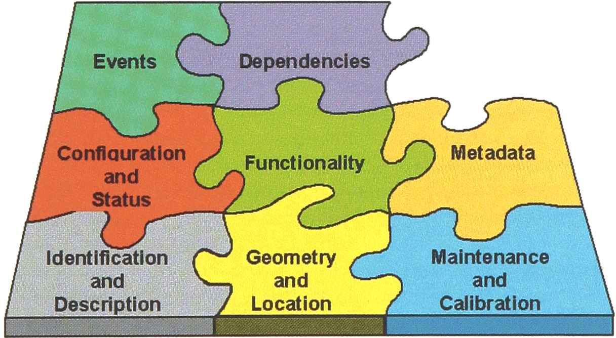
Components of a capability Set
IDENTIFICATION AND DESCRIPTION
The identification components are used for configuration management and audit information for devices in the laboratory automation system, including the manufacturer's name, device name, device software version, etc.
GEOMETRY AND LOCATION
This block holds the descriptions of physical size, shape, and location of objects and their accessible parts. Robotic paths or curves for accessing the devices ports are also parts of this block. At the system level, this information is used for robot collision avoidance.
MAINTENANCE AND CALIBRATION
Information about maintenance and calibration is used for validation and quality assurance purposes.
CONFIGURATION AND STATUS
Both hardware and software configurations are stored in a capability dataset. The capability dataset contains configuration constraints, as well as the current configuration of the objects. These data ease the configuration of a device and reduce the chances for incorrectly configuring a device. Configuration parameters are needed to set the proper functionality of a device via user methods. Status information is usually used to monitor the actions of the devices on the workbench.
FUNCTIONALITY
This block describes commands and their functions along with the types and ranges of any associated command data. This information enables the controller software to interact with the device, because the software can both know the commands and how to use them.
METADATA
Capability datasets contain metadata for any data that can be sent from a device and which must be processed by the system. These metadata include result data as well as status, maintenance data, and calibration data. Metadata describe both the type and structure of data.
EVENTS
Device events are messages sent from the device to the controller. They are categorized into different classes such as warning, alarm, error, and data.
DEPENDENCIES
This block represents concepts such as ownership management—who can access which resource and when. Also, dependencies between different devices are stored here. For example, if the system treats a chromatograph and its autosampler as two devices, the chromatograph is dependent upon the autosampler for its operation and becomes useless if the autosampler is defective, even though the chromatograph is still operable.
STATIC AND DYNAMIC SCD CONTENTS
Information enters the SCD at differing times. Some of the data are available at the time the system is designed and never change. This static part includes capabilities of the systems devices such as command sets, events, and geometry. Other SCD information is dynamic and is not known until runtime-for example, the sample locations, the actual status of instruments, and the current amounts of reagents on the workbench. Device configurations can change constantly, and even the current position of some components on the workbench can change. It is essential that the SCD provide a means for keeping track of components and their positions on the workbench. The SCD must track which device has permission to use a shared resource or port.
As an example of the data stored in the System Capability Dataset, let us examine some characteristics of a port (see Figure 2). Ports are the access points into or out of a device. A physical port can be a rack position, a door, or some other point that can be reached by other components of the system. Data ports can be considered in much the same way as their physical counterparts.
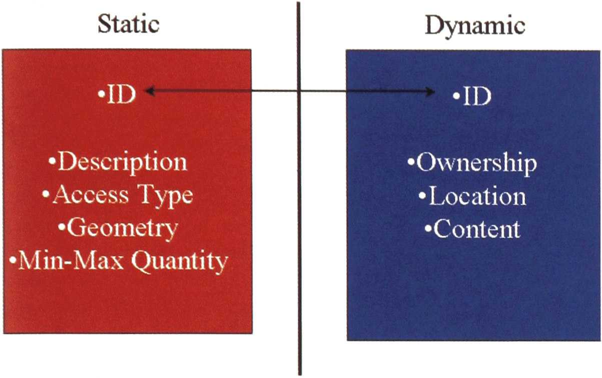
Static-Dynamic Characteristics of a Device Port
Each port, as with every other entity in the SCD, has its own unique identifier. This identifier is the same for the static instance and its corresponding dynamic part. Every dynamic port definition must have a static counterpart, but the converse need not be true. Among the static properties are a description, mostly to provide information for the user, an access type that defines how a port can be accessed, a geometry section that defines the shape and access points of the port, and capacity information that describes how many or how much of something the port can hold or provide.
The dynamic properties include the ownership, location, and content of the port. Only the current owner of a component's port can access it. Location refers to the current position of the port in the workspace, which is essential for accessing the port. If the port is moved, the accessing component needs to know this. Perhaps the most interesting property of the port is its content. A port can contain either a material such as a sample, reagent, or waste, a resource such as a pipette tip or vial, or data either flowing into or out of the device.
SCD CREATION
Figure 3 shows a timeline for the creation of an SCD. First, the device manufacturers provide the information that describes the identification, the functionalities, and the general behavior of the devices. This information forms the core of the DCDs for the devices.
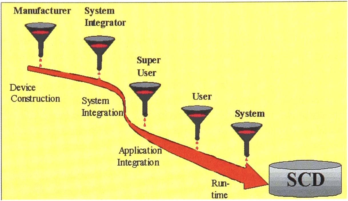
SCD creation timeline.
Next, the system integrator combines all of the DCDs and adds system-specific information about each device's role, position in the system, error handling, error mapping and ownership of resources. “Super users,” who develop analytical methods, set up the system with analytical procedures and add in the information about these. Thus far, most of the information incorporated into the SCD is static. Application users enter the parameters for specific runs, such as the number of samples or a specific temperature for a device. This sort of information is considered semi-static, because although it is known when the run starts, the values can change as the run progresses. Finally, during runtime, the system supplies information to the SCD about its current state. These dynamic characteristics are primarily used for process monitoring.
WHY USE EXPRESS TO DESCRIBE CAPABILITY DATASETS?
To construct a capability dataset that is easily reusable from system to system without significant reconstruction, we must describe the device characteristics as abstractly as possible. The representational scheme we choose should be independent of the device being described, and the device/system description must be completely independent from the implementation or the platform used. Once created in this way, device information can be used as long as the device itself is used. Even when the implementation changes, the device description is not lost. To achieve the implementation independence of the capability dataset, we need a neutral mechanism that is capable of describing product data.
The information modeling language EXPRESS, contained in ISO 10303 (STEP), fulfills this requirement. [3] It is an international standard for the computer-interpretable representation and exchange of product data. It is very important to note that STEP focuses not only on what the data are, but also on what they mean and how the data relate to one another. Originally, STEP grew out of a need to exchange product data among different computer-aided design (CAD) systems. However now, it is being used in a variety of applications from metal parts fabrication to chemical plant design. The wide scope of STEP applications means that many elements of STEP have already been invented by others. We can utilize these elements such as 2D and 3D geometric description schemes and tolerancing mechanisms, which have already been developed and tested, without having to create them ourselves. Conversely, the elements that we create may be useful to others who want to utilize our device characterizations and, perhaps more importantly, our descriptions of result data. This reusability of models is a big advantage to our approach.
IMPLEMENTATION
The capability dataset approach purposefully isolates the description of the device and system from the implementation. EXPRESS provides us with a stable, international standard for representing the SCD without worry about databases, types of databases (relational, object-oriented,…), or other implementation tools. [4] However, at some point, we must actually be able to access the SCD and its data. Furthermore, the SCD should be transparently accessible via a network in a distributed laboratory computing environment. We can do this by creating a standard interface for the SCD. In our current work, we define the interface in CORBA-IDL (Common Object Request Broker Architecture-Interface Definition Language). [9] CORBA provides the vendor, operating system, and programming language independence and functionality we need and is widely used in industry for the implementation of distributed systems. However, CORBA is not the only way to realize this interface. Other distributed component technologies such as Microsoft's DCOM could also be used. DCOM and CORBA are closely related system architectures and allow communication over software bridges. Since DCOM clients can easily access CORBA servers, and CORBA is an independent standard, we feel at present that the interface definition is better done in CORBA-IDL.
The following example shown in Figure 4 lists a fragment of an interface definition for an SCD. Here, the interface ISSystemEvent can be used to maintain system-wide event handling. This example is defined in CORBA 2.0 IDL. The specific implementation of the interface can be done in any programming language for which a CORBA-IDL language mapping exists.
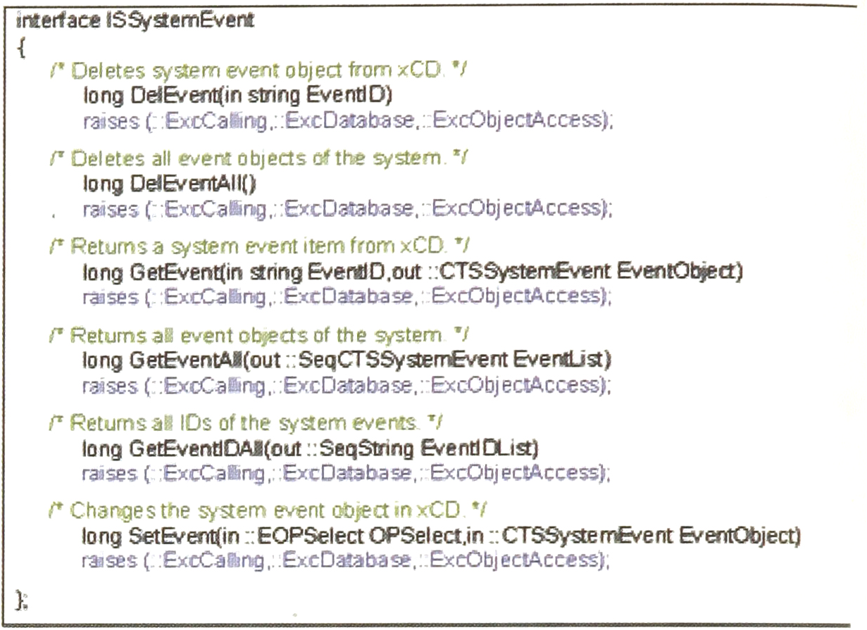
A Fragment of an SCD Interface in IDL.
Figure 5 shows the transformation path for SCD data from the abstract EXPRESS data definitions to an implementation with a system interface useable with a distributed computing technology.
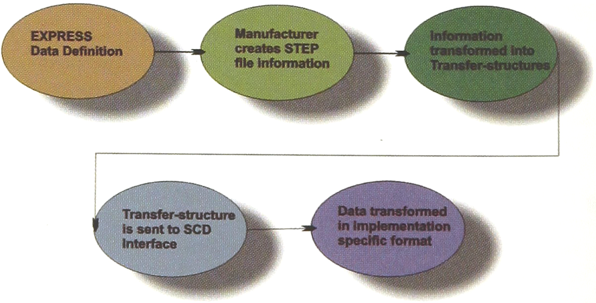
SCD Transformation from Abstract Representation to Implementation 3.
The abstract EXPRESS data definitions of the SCD should eventually become part of an international standard, such as STEP, and should be flexible enough to allow a device manufacturer to describe all device properties and behaviors. An instrument manufacturer provides descriptions of the devices and components in STEP-like files using the SCD EXPRESS data definitions. This information is converted into transfer structures that can be understood by the capability dataset interface. These transfer structures are then stored in the underlying database in an implementation-specific format. The transformation of the capability dataset information supplied by the device manufacturer to the implementation-ready form is carried out in an automated fashion.
Our initial version of the SCD data definitions is complete. [10] The next step, to implement the SCD concept for real devices, is currently underway at the National Institute of Standards and Technology in collaboration with the Wiesbaden Computer Integrated Laboratory (WICIL) at the Fachhochschule Wiesbaden, University of Applied Science.
CONCLUSION
If laboratory automation is to live up to its potential and promise, we must develop techniques to make the construction and integration of such systems far easier, cheaper, and faster. The System Capability Dataset concept offers a way to describe the capabilities and behaviors of system components abstractly and a means to represent device interactions and dependencies. The EXPRESS representation of the SCD provides a stable, implementation-independent, standard method to hold information that can easily be converted for implementation. The SCD is a first step in providing a standard representation of the laboratory workbench environment. Coupled with other standards like CORBA, it should provide a stable foundation for facilitating the building of this complex laboratory workbench computing environment allowing us to extend the capabilities and the productivity of future integrated automated systems.
Footnotes
ACKNOWLEDGMENT
This project is funded in part by NIST's Systems Integration for Manufacturing Applications (SIMA) Program. Initiated in 1994 under the federal government's High Performance Computing and Communications effort, SIMA is addressing manufacturing systems integration problems through applications of information technologies and development of standards-based solutions. With technical activities in all of NIST's laboratories covering a broad spectrum of engineering and manufacturing domains, SIMA is making information interpretable among systems and people within and across networked enterprises.