
Abstract
A Device Capability Dataset (DCD) describes the idiosyncratic characteristics of laboratory equipment, such as the equipment's identity, physical dimensions, location, supported command set, generated events, input-output (I/O) ports, and other resources. The DCD concept provides a means for standardizing the interfacing of laboratory automation devices in a descriptive rather than a prescriptive manner.
Keywords
INTRODUCTION
Every laboratory automation engineer's dream is to have instruments that are interfaced to a computer simply by plugging them into an I/O port and loading some software to make the computer operating system aware of the instrument and what it can do. Commands and data should be transported among common computer programs such as spreadsheets or simple BASIC-like control programs as easily as we print a page from such programs today. Unfortunately, for laboratory automation systems integrators, this concept is still just a dream. The technology to make this possible is readily available, but the incompatibilities in the way different devices work with the computer turn building a new device into an automation system into a science-project—in short, our dream is stymied by a lack of standards.
However, we must remember that it was not very long ago when interfacing a simple printer to a computer and its operating system was a far greater chore than it is today. In the not too distant past (early 1970's), special cables and hardware were often required and custom printer drivers were always needed, not just for every particular type of printer, but for each software application as well. So, how did it get to be so easy to print a page from a computer? Again, the answer is standards.
There are two approaches to interfacing standards: prescriptive and descriptive. The former approach seeks to make all devices look and behave the in same fashion to the controller. The latter concept is to employ a common way to describe the idiosyncrasies of the device and its behavior. Where aspects of devices can easily be made similar, such as communication hardware and software, the prescriptive method is a powerful solution. The 9-pin EIA-232 serial and IEEE-1284 bi-directional parallel ports found on modern PCs and interfacing standards such as GPIB (IEEE-488) and the TCP/IP components of network connections are good examples of prescriptive standards.
But such standards require the development of consensus in a market sphere that dwarfs the world of laboratory automation. Prescriptive standards can also be constraining to future progress, because new concepts have to be exceptionally promising to gain acceptance over entrenched standards—witness the long overdue development of high speed serial links such as the USB (Universal Serial Bus) ports that are now appearing on PCs, but alas still without much peripheral or software support. Finally, some instrument manufacturers, believing that prescriptive standards limit their ability to differentiate their products from those of their competitors, are apprehensive about supporting prescriptive interfacing standards.
Because it is not possible, nor even desirable, to make every automation device look or behave the same, other means must be found to accommodate differences. The descriptive approach, which we describe here, does just that. However, it is not a fully novel concept for computer interfacing. Similar approaches are currently being used to make printer interfacing easy. Adobe Systems, Inc. (Mountain View, CA) developed the concept of PostScript Printer Description files (PPD files) to provide a uniform approach to using the diverse special features found in devices that contain PostScript interpreters. PPD files are human-readable, machine-parsable text files that allow generic printer drivers to support a variety of printer features such as different page sizes, color or black and white printing, simplex or duplex printing, film handling, varying font availability, document sorting, and stapling. “The information contained in PPD files serves as a list of available features, as a basis for building a user interface, and as a mechanism for invoking the features on a particular device” [1]. The DCD concept was conceived independently of the PPD notion and extends the descriptive standard idea to a much larger class of devices and scope of control.
The first steps toward the definition of a standard Device Capability Dataset (DCD) were taken by participants of the Consortium on Automated Analytical Laboratory Systems (CAALS) Modularity Working Group at the National Institute of Standards and Technology (NIST) about five years ago. Since then, research on the DCD topic has continued at NIST and the Fachhochschule Wiesbaden (FHW), University of Applied Sciences [2–5]. Initial results of this joint research effort were presented at the LabAutomation'98 conference in San Diego in January 1998. The System Capability Dataset (SCD), a further extension of the DCD idea that accommodates individual DCDs as well as interactions, roles, and dependencies between devices in a system, is described in the following article and elsewhere [6,7]. Figure 1 depicts the generic CAALS logical control architecture [8] showing the relationship of the DCDs and the SCD.
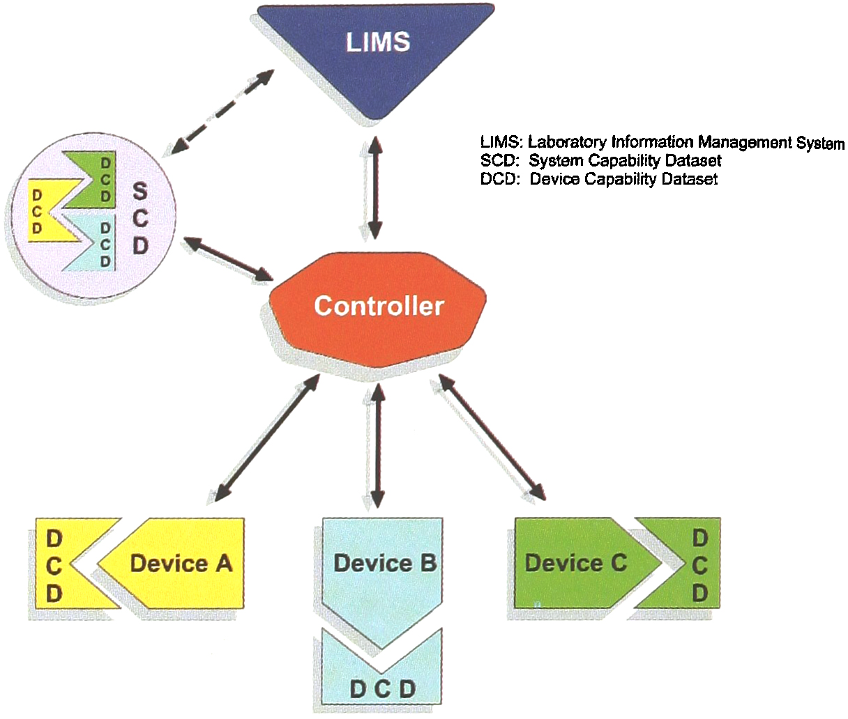
CAALS Modularity Architecture Logical Model
STRUCTURE OF DEVICE CAPABILITY DATASETS
A Device Capability Dataset, comprised of various types of information about the device, its operations, and its resources, can be organized into the following categories:
IDENTIFICATION
COMMUNICATIONS
PHYSICAL CHARACTERISTICS
I/O PORTS
COMMANDS
EVENTS
EXCEPTIONS
ERRORS
RESOURCES
MAINTENANCE
In programming language terminology such categories are the equivalent to classes or structures. Representative data and their datatypes contained in these DCD categories are detailed elsewhere [2,7]. The above DCD categories are still under development and therefore are neither final nor complete.
STATIC VS. NON-STATIC DEVICE CAPABILITY DATA
Not all the data in DCD categories have the same temporal nature. Some information such as the device manufacturer's name will not change throughout the lifetime of the device and so can be considered static. Other facts, such as resource amounts and consumables, change during the operation of the device and must be accounted for dynamically. There are cases between these two extremes that range from semi-static to semi-dynamic data. Analytical method names could be an example of semi-static data, while a device's initial fill level might constitute semi-dynamic data. The exact temporal attributes assigned are less important than the concept that data in a DCD can vary in both their time of inclusion and their longevity. A multi-author, multi-session creation DCD process is implicit in this notion. A DCD is created along a multi-step path beginning with the instrument manufacturer who imparts much of the static data. The system integrator and methods developer supply additional static, semi-static, and semi-dynamic data. And the system itself during run time, updates many of the dynamic data.
DCD REPRESENTATION AND ACCESS
Currently, no consensus for the format for the storage and representation of Device Capability Datasets exists. Whichever format is ultimately chosen for the DCD representation standard should be flexible, extensible, machine-interpretable, and computing platform-independent. To make the DCD idea work, we will either have to standardize on a single abstract metadata representation scheme or utilize compatible schemes that can be reliably interconverted electronically. [Metadata are data about data; for example, the metadata description of a field in your address book would include the maximum length of the field, acceptable fonts to be used, etc.] Data/interface modeling languages such as the eXtensible Markup Language (XML) [9]. the Interface Definition Language (IDL) [10], or EXPRESS [11–14] are all current contenders for the abstract representation of a Device Capability Dataset.
DEVICE CAPABILITY DATASETS IN XML
XML is an extensible mark-up language that allows structured document data interchange. It was developed under the auspices of the World Wide Web Consortium (W3C) and was standardized by the W3C in February 1998. XML differs from other mark-up languages such as the more familiar Hyper Text Markup Language (HTML) in that XML is a meta language that allows design of an individualized mark-up language. XML is a subset of the Standard Generalized Markup Language (SGML), which is defined in ISO Standard 8879:1986.
By defining the role of each element of data in a formal model, known as a Document Type Definition (DTD), XML users can check that each component of the Device Capability Dataset occurs in a valid place within the interchanged data stream. But, unlike SGML, XML does not require the presence of a DTD. If no DTD is available, either because it is not accessible or because the device manufacturer did not create it, an XML system can assign default definitions for the undeclared components of the markup. Figure 2 depicts a small XML document.

A Simple DCD Example in XML
The hierarchical and object-orientated natures of XML files allow them to be adapted to virtually any type of database. Since XML is platform-independent, DCD data can be transferred to a wide range of hardware and software environments. Furthermore, a standardized interface to XML data is defined through W3C's Document Object Model (DOM), which provides a CORBA (Common Object Request Broker Architecture) interface between applications exchanging XML data. A variety of free XML tools and libraries with XML APIs (Application Programming Interfaces) exist that allow users to create, read, parse, and modify XML documents programmatically.
DEVICE CAPABILITY DATASETS IN IDL
The Interface Definition Language (IDL) provides another way to represent Device Capability Datasets in a device- and platform-independent form. IDL has been standardized by the Object Management Group (OMG), a consortium of over 800 software vendors, software developers and end users. IDL is a simple language used only for defining interfaces, instead of writing programs. It permits the description of any resources or services that the device (server) wants to expose to its controller (client). Since IDL is a declarative language, i.e. it separates interfaces from implementation details, IDL-specified device interfaces can be implemented in any language for which a language mapping exists. For example, the equipment's interface software could be written in C, in a case where the corresponding controller software is entirely written in ADA. OMG IDL language mapping currently exists for Java, C, C++, Smalltalk, COBOL, and ADA languages.
The IDL grammar is very similar to that of the C++ programming language. However, IDL provides additional keywords to support distributed concepts. It supports C++ like syntax for constants, type, and operation declarations. IDL allows specification of the attributes of a device, the parent classes from which the device inherits, the exceptions it raises, typed events, and the methods the device interface supports—including input and output parameters and their data types. Figure 3 shows a model and representation of a Device Capability Dataset in IDL.
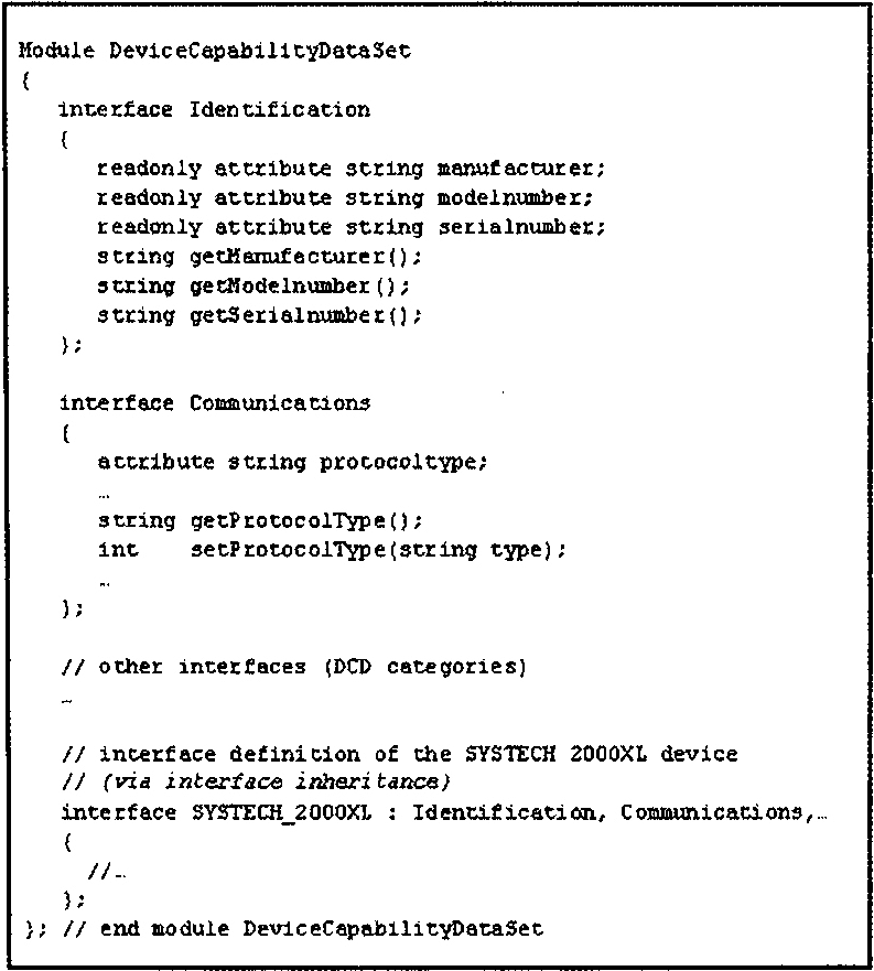
A Simple DCD Described in CORBA-IDL
After the device interface has been specified in IDL, an IDL compiler is used to generate the skeleton (stub) code for the client and server in the implementation language of choice. After this, the instrument programmer must write an implementation of the device interface in the target language.
Subsequent to choosing IDL to define an instrument interface with IDL. one needs to decide which distributed component technology to utilize. This decision determines how the device interface, and therefore also the DCD, is accessed. Currently, the major technologies in this area are OMG's CORBA, Microsoft's DCOM (Distributed Common Object Model), or OSF's (Open Software Foundation) DCE (Distributed Computing Environment). Each of these technologies provides its own version of IDL, i.e., CORBA IDL, MIDL (Microsoft's IDL), and DCE IDL, and these IDLs are not identical. The decision to choose CORBA, DCOM, or DCE depends largely on the technology utilized by the target market. Fortunately, the IDL choice is not really a point of no return No choice irrevocably commits to only that particular technology, because software tools exist that convert between the various dialects of IDL. Furthermore, there are so-called software bridges that permit cross-technology interfacing. For example, using a bridge, a DCOM-represented controller object can interact with an instrument object that is encapsulated in CORBA.
DEVICE CAPABILITY DATASETS IN EXPRESS
The EXPRESS language provides yet another way to represent device capabilities in a universal, device- and computing-platform-independent format. EXPRESS is part of the ISO 10303 standard, commonly known as STEP [Standard for the Exchange of Product Model Data] [11–14].
ISO 10303 is an international standard for the computer-interpretable representation and exchange of product data. The objective is to provide a neutral mechanism capable of describing product data throughout the life cycle of a product, independent from any particular computer system. In addition to STEP's suitability for neutral file exchange, it also provides a basis for implementing, sharing, and archiving product databases. The ISO 10303 standard permits different implementation technologies to be used for storing, accessing, transferring, and archiving product data. STEP is intended to be both human-readable and computer-interpretable to facilitate human understanding while expediting the generation of computer-interpretable applications and support tools. Because of the general applicability of EXPRESS for the representation of DCDs and the broad understanding and knowledge of STEP and EXPRESS at NIST the DCD development at NIST is being done in STEP [2,7]
As with XMLs DTD file, EXPRESS has a file called the schema file. The EXPRESS schema file is used to describe the structure and types of data. Figure 4 shows a very simple EXPRESS schema file.
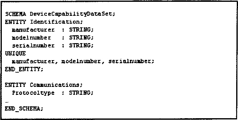
A DCD Schema in EXPRESS (ISO 10303–12)
EXPRESS provides language constructs for the definition of entities (structs), user-defined data types, enumerations, unions, data arrays, optional data, and much more. It also permits the definition of nested entities and referencing STEP- or user-defined schemes.
ISO 10303–21 is me STEP Clear-Text-Encoding standard [14], which can be used to describe data that are modeled with EXPRESS schema. A STEP clear-text-encoded DCD file consists of two sections: HEADER and DATA. The HEADER section provides data relating to the structure of the Device Capability Dataset, while the DATA section holds the actual data. Figure 5 shows an example of an ISO 10303–21 clear-text-encoded file.
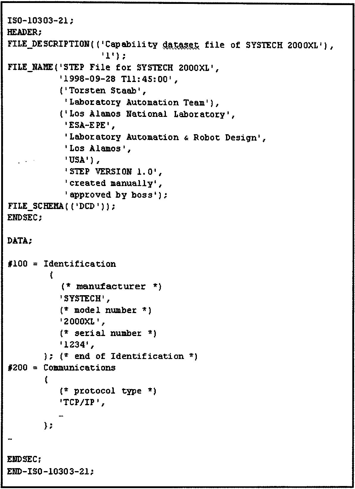
A simple DCD in Clear-Text-Encoded EXPRESS format (ISO 10303–21)
A number of tools exist for generating EXPRESS-compliant datasets ranging from EXPRESS schema and data editors to EXPRESS-to-C++ and EXPRESS-to-HTML converters. There are also programming libraries available that allow storage/retrieval of EXPRESS-modeled data to/from relational and object-oriented databases. More information on STEP and EXPRESS tools can be found on the web at: www.steptools.com [STEP Tools, Inc. (Troy, NY)].
DCD ACCESS AND LOCATION
DCDs can be stored in anything from a simple ASCII file to a high-performance relational or object-oriented database. An entire DCD need not be constrained to a single type of storage representation—the static and dynamic DCD information could reside in different locations on different media. For example, the static parts of the Device Capability Dataset information might be stored in an instrument's ROM (Read-Only Memory), on disk, or even on a networked server provided by the device manufacturer. The dynamic part could reside either in flash memory, on disc, or in random access memory.
It is crucial for the controller to have access at run time to the DCDs of all devices under its control. A controller could access a device's DCD either directly using special data commands or indirectly through normal control channel communications. Figure 6 illustrates both direct access (yellow device and DCD) and indirect access (green device and DCD) to the Device Capability Dataset information.
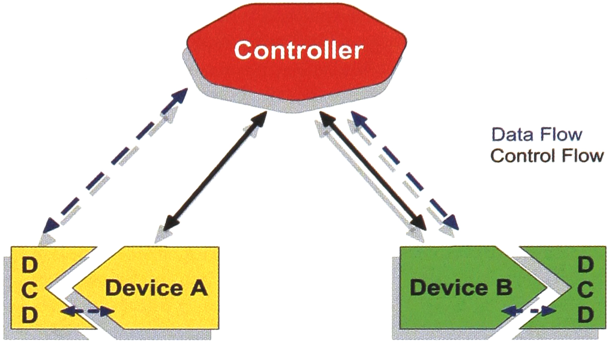
DCD Access Topologies
Dynamic DCD information is more likely to reside in the instrument's local controller. The system-level device controller could retrieve such information either on demand or as a result of receiving an event message. On-demand means that the controller explicitly asks the device for DCD information, and this request initiates a download of the static and dynamic DCD information from the instrument. In the event-driven model, the device informs the controller each time a DCD characteristic changes by sending an event message.
CONCLUSION
In general, laboratory automation system integration is getting easier. Simplified device communication brought on by the near total acceptance of networking standards such as Ethernet and TCP/IP along with built-in device communication support in modern operating systems like WinNT has eliminated many of the previous problems of how to get messages between devices and controllers. Descriptive standards based on the Device Capability Dataset concept offer a powerful mechanism for simplifying and facilitating the problems of what messages to send between devices and controllers.
Currently, the choice of DCD format representation is still undecided. Although NIST's current prototype implementation efforts are concentrating on using EXPRESS for the abstract DCD definitions and CORBA IDL for DCD implementation, it is not clear at this point whether this is the way the industry will go. However, the availability of interconversion tools may render this point moot. The basic concept and structure of the DCD has been defined, and projects at NIST and FHW are currently underway (elsewhere others are now being planned) to create DCDs for real laboratory devices and to demonstrate the feasibility and real world benefits of the DCD approach.
Footnotes
ACKNOWLEDGMENTS
This project is funded in part by NIST's Systems Integration for Manufacturing Applications (SIMA) Program. Initiated in 1994 under the federal government's High Performance Computing and Communications effort, SIMA is addressing manufacturing systems integration problems through applications of information technologies and development of standards-based solutions. With technical activities in all of NIST's laboratories covering a broad spectrum of engineering and manufacturing domains, SIMA is making information interpretable among systems and people within and across networked enterprises. The authors would like to acknowledge the work of the participants of the CAALS Modularity Workshops, who established the basis for this work—in particular: James R. DeVoe, Lawrence G. Falkenau, J. Michael Griesmeyer, Franklin R. Guenther, David R. Hawk, Richard S. Lysakowski, Marc L. Salit, Brian D. Seiler, William J. Sonnefeld, and John Upham. Furthermore, we are grateful for the valuable contributions of: Anthony J. Day, Uwe Bernhöft, Peter J. Grandsard, Christian Piotrowski, Thorsten Richter, Mark F. Russo, and Reinhold Schäfer.