
Abstract
Microfluidic devices offer new technical possibilities for a precise manipulation of Caenorhabditis elegans due to the comparable length scale. C. elegans is a small, free-living nematode worm that is a popular model system for genetic, genomic, and high-throughput experimental studies of animal development and neurobiology. In this paper, we demonstrate a microfluidic system in polydimethylsiloxane (PDMS) for dispensing of a single C. elegans worm into a 96-well plate. It consists of two PDMS layers, a flow and a control layer. Using five microfluidic pneumatic valves in the control layer, a single worm is trapped upon optical detection with a pair of optical fibers integrated perpendicular to the constriction channel and then dispensed into a microplate well with a dispensing tip attached to a robotic handling system. Due to its simple design and facile fabrication, we expect that our microfluidic chip can be expanded to a multiplexed dispensation system of C. elegans worms for high-throughput drug screening.
Introduction
In drug screening, vertebrate animals such as mice have widely been used as model organisms to test potential therapeutics before their translation into human clinical trials. 1 Recently, the relatively simple invertebrate animal Caenorhabditis elegans, which shares many homologs and important signaling pathways with humans, has been developed as a rapid, low-cost alternative for high-throughput whole-organism drug screening.2,3 C. elegans is ideally suited for high-throughput screening in 96- or 384-well microplates because it reproduces rapidly, is optically clear throughout its life cycle, is very small (35–40 µm in diameter and 1 mm in length), and can be easily maintained as genetically homogeneous lines. 4 At the same time, however, its small size poses a formidable challenge to automated handling and dispensing for high-throughput screening. 5
To dispense C. elegans worms into a microplate well, commercial system COPAS FP is available that is designed for dispensing large objects ranging from 20 µm to 1500 µm based on capillary-based fluorescence-activated cell sorting (FACS) technology. 6 Due to the high cost of this automatic sorting system, however, many labs still use a simple peristaltic pump for high-throughput assays, in which a reservoir of worms suspended in liquid medium is used to dispense worms into the microplates. A drawback of this simple alternative method is that the number of worms dispensed cannot be controlled precisely, resulting in variability between assays. To accurately quantify and compare the effect of drugs between individual wells, there is a need for a simple dispensing unit to count and dispense a specific number of worms accurately and rapidly.
Microfluidic systems with a channel size comparable to that of a C. elegans worm are ideally suited for its manipulation.5,7 Applications ranging from laser surgery 8 to phenotypic analysis 9 have been reported using microfluidic devices with flexible polydimethylsiloxane (PDMS) pneumatic valves for trapping and immobilizing worms. 10 However, no microfluidic system has yet been reported to directly dispense a precise number of C. elegans worms into a microplate well. In this paper, we demonstrate a microfluidic system that can trap and dispense a single worm into a microplate well. This system uses microfluidic pneumatic valves in the control layer to trap a single worm upon optical detection and then dispenses it into a microplate well from the outlet of the flow channel via a dispensing tip. Due to its simple design and facile fabrication, this module could be expanded to form the basis of a multiplexed system to dispense C. elegans worms for high-throughput drug screening.
Materials and Methods
Fabrication of the Microfluidic Chip
The microfluidic chip consisted of two PDMS layers: a fluidic layer on the top and a pneumatic control layer on the bottom, as described previously. 10 A detailed description of the fabrication steps can be found in Supplemental Figure 1S of supporting information.
On-Chip Integration of Optical Fibers
The detection mechanism in our device was based on the light scattering when a worm passes by the optical gate 11 in the constriction channel that was required to decelerate the flow of C. elegans worms. On the launching side of the optical gate, the optical fiber was connected to a laser light source with a wavelength of 660 nm (Thorlabs, Newton, NJ, S1FC660). On the detection side, the optical fiber was connected to a photodiode (Thorlabs, FDSP625) and coupled to a LabVIEW program through an Arduino board. The optical fiber used for the prototype had a diameter of 125 mm with a core diameter of 105 µm (Thorlabs, FG105UCA; NA = 0.22). After bonding the PDMS chip on a plasma-treated glass slide, two stripped and cleaved optical fibers were lubricated using ethanol and inserted gently into the prepatterned grooves for optical fibers. The two ends of the optical fiber were placed 100 µm away from the fluidic channel perpendicular to the constriction channel. The semitransparent nature of the worms caused the light to be partially absorbed as well as diffracted. 11
Trapping and Dispensing Method
The trapping mechanism for this device was based on the PDMS valving system, and this technique has successfully been applied to worm manipulation, such as immobilization. 10 After trapping, a syringe pump (Era Pump Systems Inc., Farmingdale, NY, NE-1002X) was turned on to pump M9 buffer solution for 20 s at a flow rate of 30 mL/min and dispensed the worm into the microplate via tubing with a dead volume of ~10 mL connected to the outlet of the microfluidic chip.
Characterization of Dispensing Performance
In order to characterize the device, we desired a uniform size of worms. Following the standard lab procedure for the synchronizing developmental stage, adult wild-type (N2 strain) worms were treated with bleach and unhatched embryos, which are protected from this treatment by an impermeable eggshell, were collected. Animals synchronized in this way were allowed to grow on agar plates supplemented with OP50 bacteria. After reaching the fourth larval (L4) stage, worms were washed from agar plates with M9 buffer and diluted to a concentration of ~25 worms/10 mL droplet. To characterize the dispensing accuracy and speed, two dispensing experiments were conducted in 10 microplate wells at three different flow rates (3, 5, and 7 µL/min) using two different constriction channel sizes (30 and 40 µm). The dispensing accuracy was measured by counting the average number of wells with a single worm. Once the dispensing in 10 wells was completed, a rapid and accurate high-throughput image analysis was performed using the image analysis system DevStaR to measure the dispensing accuracy.
Results and Discussion
The microfluidic dispensing system with a microfluidic chip and a dispensing tip that was connected to the chip outlet via tubing is shown in Figure 1a . A robotic arm was used to move the tip from well to well. The PDMS microfluidic chip had five integrated pneumatic microvalves (marked as green lines in the chip), which were controlled by a manifold, as well as a pair of the optical fibers connected to a laser source and a photodiode. To monitor the detection and trapping of worms, the microfluidic chip was initially mounted underneath a stereoscope. When improving the dispensing speed, it was mounted directly on the robotic arm so that the amount of dead volume between the outlet and the dispensing tip could be minimized. The worm suspension and M9 buffer solutions were supplied separately to the microfluidic dispensing chip via two syringe pumps. The syringe supplying the worm suspension had two vibrating actuators attached to its bottom to prevent the worms from settling down. The dispensing operation is shown in Supplemental Video 1S in supporting information. In Figure 1b , the integration of optical fibers toward the microfluidic channel, as described in the Materials and Methods section, is shown schematically. The flexible PDMS layer acting as a valve is directly underneath the fluidic channel. In Figure 1c , the closing of the microfluidic channel with a PDMS valve upon optical detection is shown schematically. The operation of the dispensing system can be seen in a video Supplemental Video S1 .
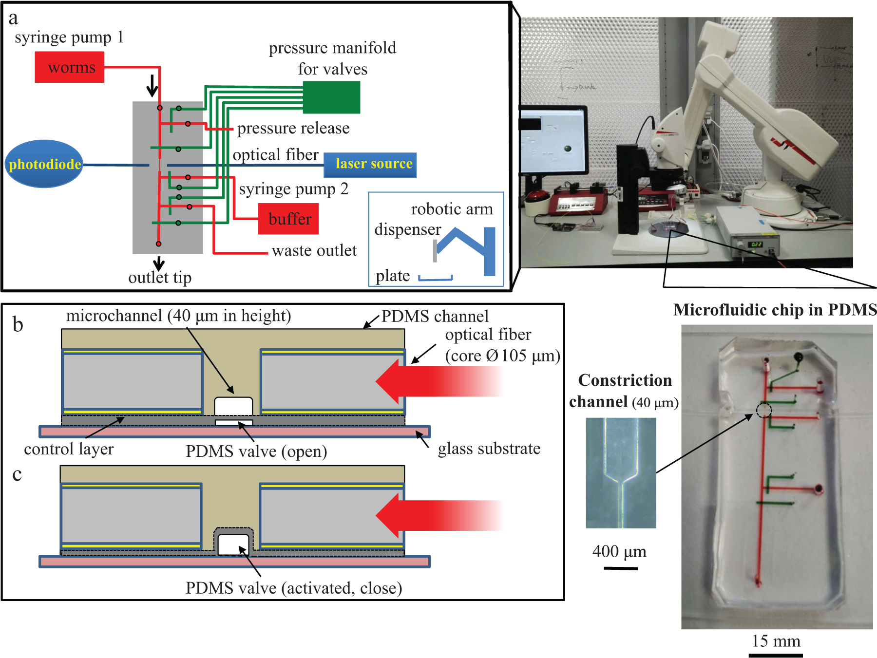
Microfluidic dispensing system for C. elegans worms. (
For trapping and dispensing of the C. elegans worms, there were five valves in the microfluidic chip integrated: valve 1, pressure bypass; valve 2, inlet; valve 3, buffer solution; valve 4, waste; and valve 5, outlet (as shown in Fig. 2a ). At the start of the procedure, a worm suspension was continuously pumped through the inlet port with pump 1. At this time, since there was no worm detected, the inlet and waste valves were open while the pressure bypass, buffer, and outlet valves were all closed. As soon as a worm was optically detected in the constriction channel, the inlet and waste valves closed while pump 1 for the worm suspension was turned off ( Fig. 2b ). The size of the constriction channel was varied between 30 and 40 µm in width at a constant length of 2 mm. This constriction channel allowed L4 stage and young adult C. elegans worms with a body diameter of approximately 45 µm pass through. It increased the transient time of worms for optical detection and trapping. The suspension was carefully prepared by trying to avoid any agar residues or eggs. However, clogging problems occurred with the 30 µm constriction channel, mainly due to worm eggs and a size variation in the L4 population at ±10%–20%. For the 40 µm constriction channel, there was no major clogging problem since the constriction channel size was suitable for L4 stage worms, even with the size variation in the L4 population. Finally, the pressure bypass, buffer, and outlet valves opened while pump 2 was switched on to flush the detected worm into the outlet with M9 buffer solution ( Fig. 2c ). A single worm inside a M9 droplet is shown as a result of dispensing ( Fig. 2d ). A pressure bypass valve was integrated in order to make sure that the pressure did not build up near the inlet port when valve 1 was closed. The detection and trapping of a worm inside the microfluidic chip is shown in Supplemental Video S2 in supporting information.
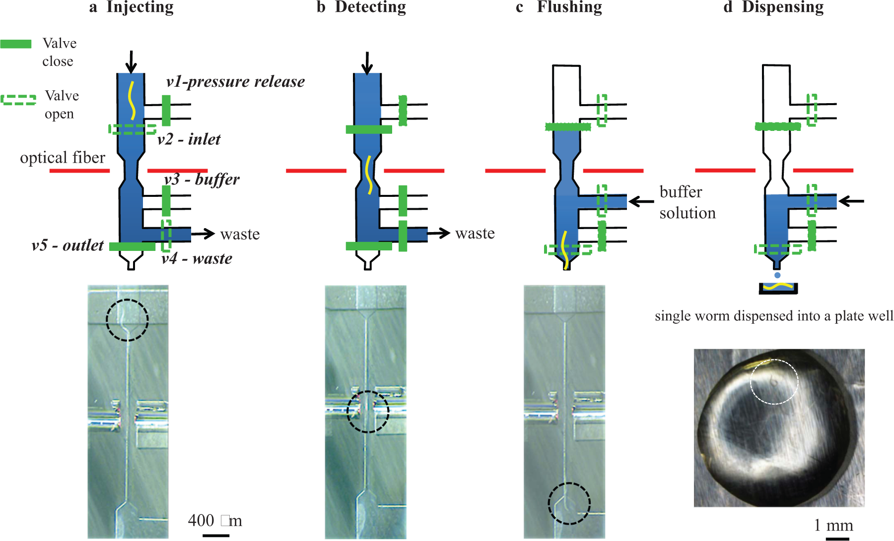
Schematics and images showing (
The delay time for switching off pump 1 had to be at least 2 s in order to make sure that the worm passed through the constriction completely. However, within this delay time, a second worm could pass through the constriction channel before pump 1 was turned off, resulting in a variation in the number of worms dispensed. To deal with this problem, the LabVIEW software scanned for a second drop of the laser signal intensity after 1 s of detection. If a second drop of the signal intensity was detected after 1 s, then these two worms were flushed out to the waste outlet. If, however, two worms followed each other very closely, which often was observed in the microchannel, then the current detection system could not differentiate between a single worm and two worms.
The most critical parameters when improving the dispensing accuracy were the flow rate, the constriction channel size, and the concentration of worms in the suspension. Using ~20–25 worms/10 µL worm suspension and a 30 µm constriction channel in a microfluidic chip mounted directly on the robotic arm ( Fig. 3a ), a dispensing accuracy of ~83.33% was achieved at a flow rate of 3 µL/min for a total dispensing time of 19.27 min ( Fig. 3b ). The total dispensing time was measured as the average time it took to dispense in 10 wells. Constriction channel sizes below 30 µm caused frequent clogging issues and therefore were not practical for dispensing. As the flow rate was increased to 7 µL/min, the dispensing accuracy decreased down to ~70% at a total dispensing time of 8.03 min. The main reason for the higher dispensing accuracy at 3 µL/min was the longer transition time of worms in the constriction channel for optical detection and trapping with the microvalves. In the case of the 40 µm constriction channel, a dispensing accuracy of 80% was achieved at a flow rate of 3 µL/min for a total dispensing time of 15.04 min ( Fig. 3c ). As implied by these dispensing results, a trade-off between accuracy and speed was necessary. In this regard, the 40 µm constriction channel was selected as the preferred channel size. Dispensing of two or more worms into a well was caused by the characteristic behavior of C. elegans to flow in a swarm, which posed a challenge to the detection and trapping of a single worm. For comparison, the data obtained with the dismounted chip from the robotic arm for observation under the stereoscope are shown in Supplemental Figures 2S and 3S in supporting information. Potential solutions to further reduce the dispensing time are a direct dispensing from the microchannel outlet into a microplate through an integrated tapered dispensing tip without connecting tube, which will cut down the dispensing time even more, and multiplexing of dispensing outlets.
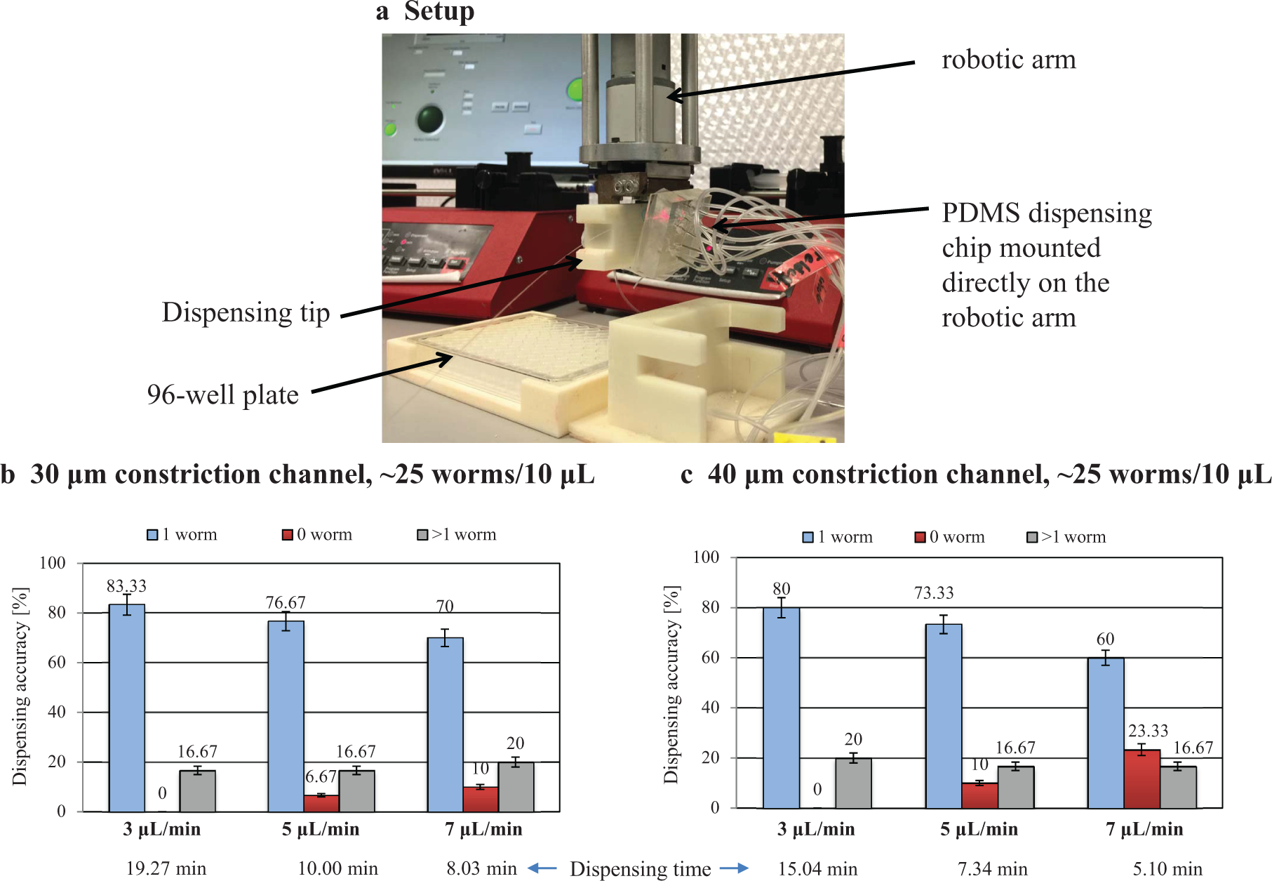
Characterization of the microfluidic dispensing chip directly mounted on the robotic arm in terms of accuracy for a single worm dispensing at three different flow rates and two constriction channel sizes, 30 and 40 µm. (
Conclusions
We developed a prototype of a disposable microfluidic chip for counting and dispensing a single C. elegans worm into a microplate for drug screening. Using an optical fiber detection system inside a constriction channel and integrated pneumatic valves, a single worm could be trapped and dispensed into a well. To integrate a standard optical fiber of 125 µm in diameter at a channel height of 37 µm, we applied two PDMS molding steps. At an initial concentration of 20–25 worms/10 µL and a flow rate of 3 µL/min, an accuracy of ~83.33% was demonstrated with a 30 µm constriction channel. Once fully developed with direct dispensing capability in a multiplexed mode, this microfluidic device can offer an economic alternative to the sophisticated and expensive dispensation system that is currently available on the market.
Footnotes
Acknowledgements
We thank Ms. Fathima Shaffra and Dr. Hala Fahs from NYUAD for providing us with the worms for the dispensing experiment. The device fabrication was performed in the microfabrication core facility at NYUAD. This work was conducted with the support of the NYU Whitehead Fellowship for Young Investigators in Biomedical and Biological Sciences 2014.
Declaration of Conflicting Interests
The authors declared no potential conflicts of interest with respect to the research, authorship, and/or publication of this article.
Funding
The authors received no financial support for the research, authorship, and/or publication of this article.
Supplementary material is available online with this article.
References
Supplementary Material
Please find the following supplemental material available below.
For Open Access articles published under a Creative Commons License, all supplemental material carries the same license as the article it is associated with.
For non-Open Access articles published, all supplemental material carries a non-exclusive license, and permission requests for re-use of supplemental material or any part of supplemental material shall be sent directly to the copyright owner as specified in the copyright notice associated with the article.