
Abstract
The LabMatrix™ is a prototyping system designed to give the user a practical and versatile platform for testing microfluidic applications in the fields of health care and life sciences. The LabMatrix™ system consists of a microfluidic breadboard and cover that align and secure a series of specially designed LabMatrix™ microfluidic chips. Chips are easily arranged and rearranged into a user-defined fluidic network. The LabMatrix™ system is designed with maximum flexibility in mind, providing the user with a means to prototype a wide range of microfluidic applications in a short period.
Keywords
Introduction
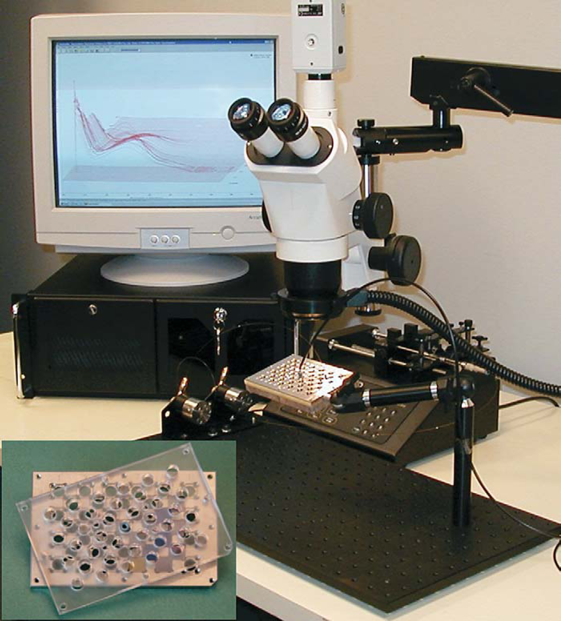
Microfluidics is an emerging technology that promises to deliver huge cost savings and versatility to the health care and life science industries through miniaturization and vertical integration of multi-component and multistep operations. The research areas most influenced by microfluidics are genomics, proteomics, high-throughput screening, and, to an extent, chemical synthesis. Products on the market today cover a wide range of applications from diagnostic analysis chips to systems for absorption, distribution, metabolism, and excretion screening to multichannel high-performance liquid chromatography systems. However, many researchers interested in exploring microfluidic technology are hindered by a lack of flexible and versatile tools suited to their specific applications. The development of application-specific microfluidic systems has been a complicated and capital-intensive process, one that creates a barrier for most researchers. The LabMatrix™ system (Figure 1) is designed to eliminate these impediments by providing a set of standard chips to probe molecular behavior in the micro environment; a detection system featuring the small swept volume and sensitivity necessary to characterize molecular signals at nano- to micro-liter flow conditions; and a system integration infrastructure to form and support the application-specific fluid network.
The LabMatrix™ System.
The LabMatrix™ system consists of a microfluidic breadboard and cover that align and secure a series of specially designed microfluidic chips to form a completely user-defined fluidic network. Included with the breadboard and chips are an optical mounting board and fixturing to position the breadboard, microvalves to control the fluid flow, syringe pumps for fluid delivery, a stereomicroscope, a multichannel UV detection system, and NanoFlow flow cells. The LabMatrix™ system also includes customized software for data acquisition and component control.
LabMatrix™ Breadboard
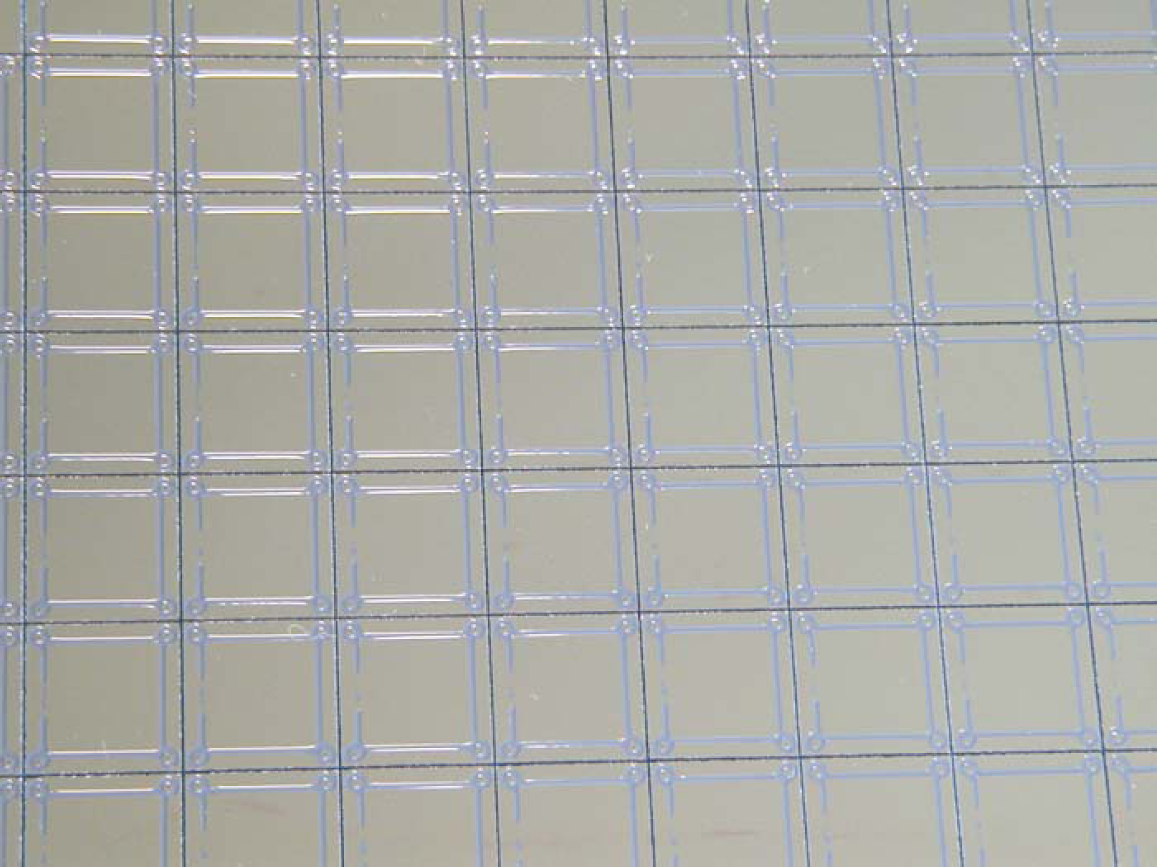
The LabMatrix™ breadboard (Figure 2) contains 39 precisely machined square pockets. An array of 24 shallow pockets (4 × 6) is separated by 15 deep pockets (3 × 5) at the interstitial locations. The depth of the shallow pockets is 1X chip thickness, and the depth of the deep pockets is 2X chip thickness. A fluid network is assembled by placing chips face up in the deep pockets and face down in the shallow. The pocket-to-pocket spacing of the breadboard assures that the corners of each adjacent chip overlap. As a result, fluid communication ports, surrounded by on-chip o-rings located at the corner of each chip, align with one another, ready to form a reliable chip-to-chip fluidic seal. After all of the desired LabMatrix™ chips are placed, the user attaches a cover plate to the breadboard. The cover secures the chips in their respective pockets. Spring-loaded screws thread into the breadboard to supply adequate force at the corners of each chip, where the fluid communication ports are located, to form a leak-free, chip-to-chip fluid connection. Access to and egress from the LabMatrix™ chip can be accomplished by tightening microfittings, with conforming ferrules, against an open fluid communication port in place of the spring-loaded screws. Holes in the breadboard and the cover plate enable optical access to the surface of the chip for fluorescent detection or fluid channel visualization via microscope.
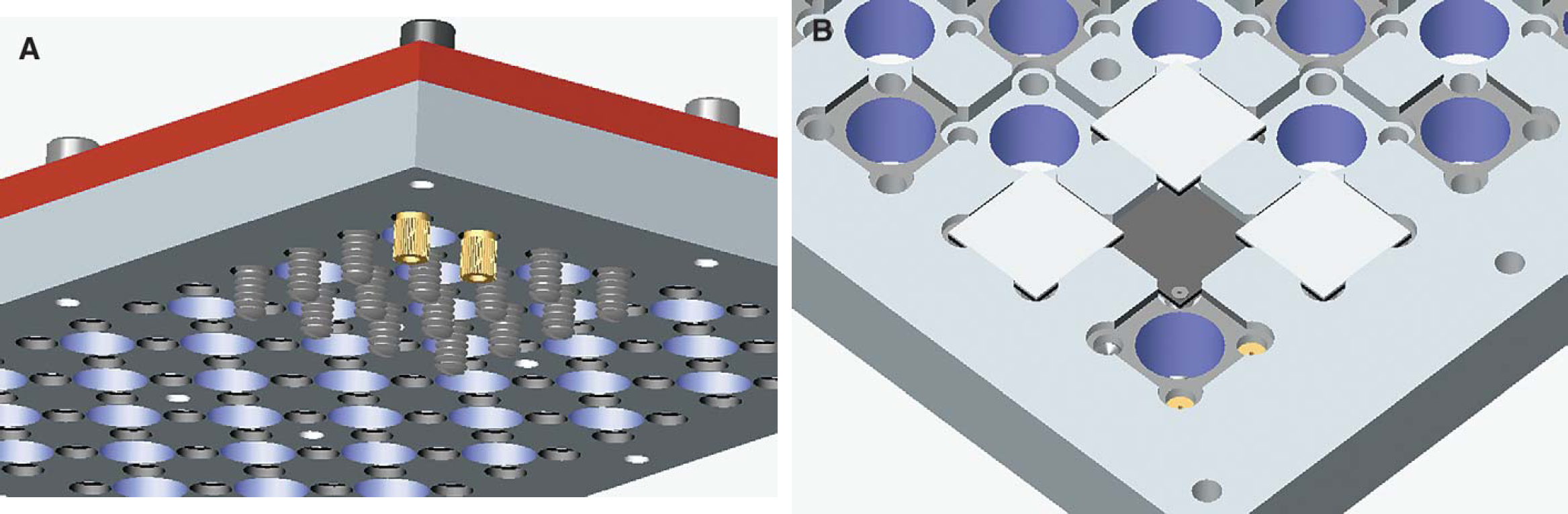
(A) Bottom view of the assembled breadboard. The red cover plate is secured atop the breadboard and two microfittings are used to provide fluid pathways to external devices. Spring-loaded setscrews and/or microfittings are tightened at each corner of the chip to generate leak-free sealing. (B) The dark chip is situated in a deep pocket with o-rings facing up, and the light chips are in shallow pockets with o-rings facing down. The overlapped corners provide sealed fluid communications.
LabMatrix™ Chips
The LabMatrix™ system utilizes two groups of chips to complete the fluid network on the breadboard: The fluid logic chips guide and direct the fluid, and the functional chips achieve a specific operational goal.
The microfluidic chips used for the LabMatrix™ system (Figure 3) are laminated structures created from single-crystal silicon and glass wafers. The chips are square in form with a fluid communication port, surrounded by a form-in-place o-ring, located at each corner of the chip. The square chip layout allows the investigator to align the chip in four distinct rotational positions for the formation of a fluid network.
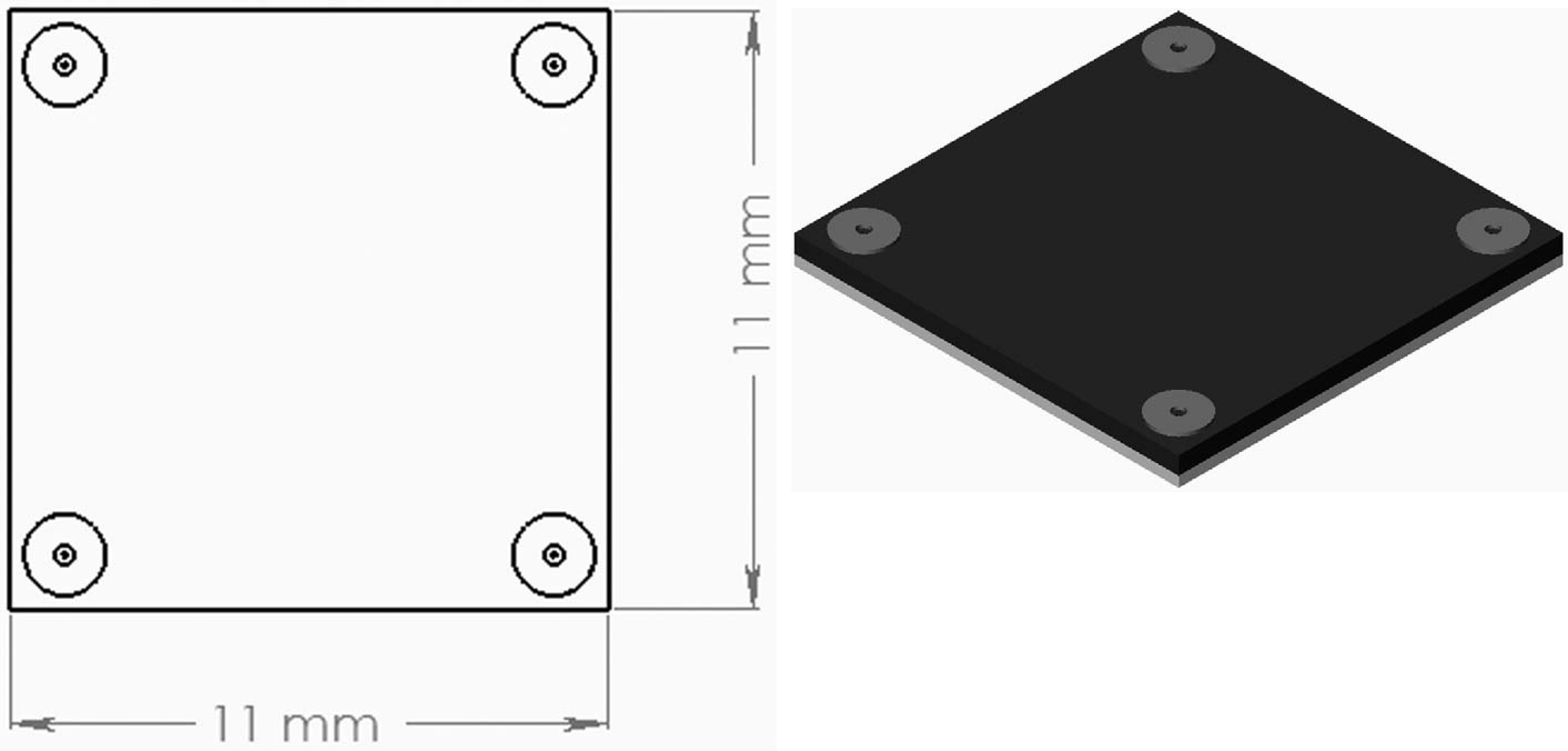
LabMatrix™ chip dimensions and isometric view.
Seven unique fluid logic chips (Figure 4) are all that is required to construct any desired network pattern. These chips are specifically designed to ensure uniformity in fluidic pathway length from any corner-to-corner regardless of their shape. Moreover, all of the channels in the Tee and Cross chips intersect at equal angles to minimize preferential fluid flow. These features help the user maintain a pressure balance in all branches of the fluid network.
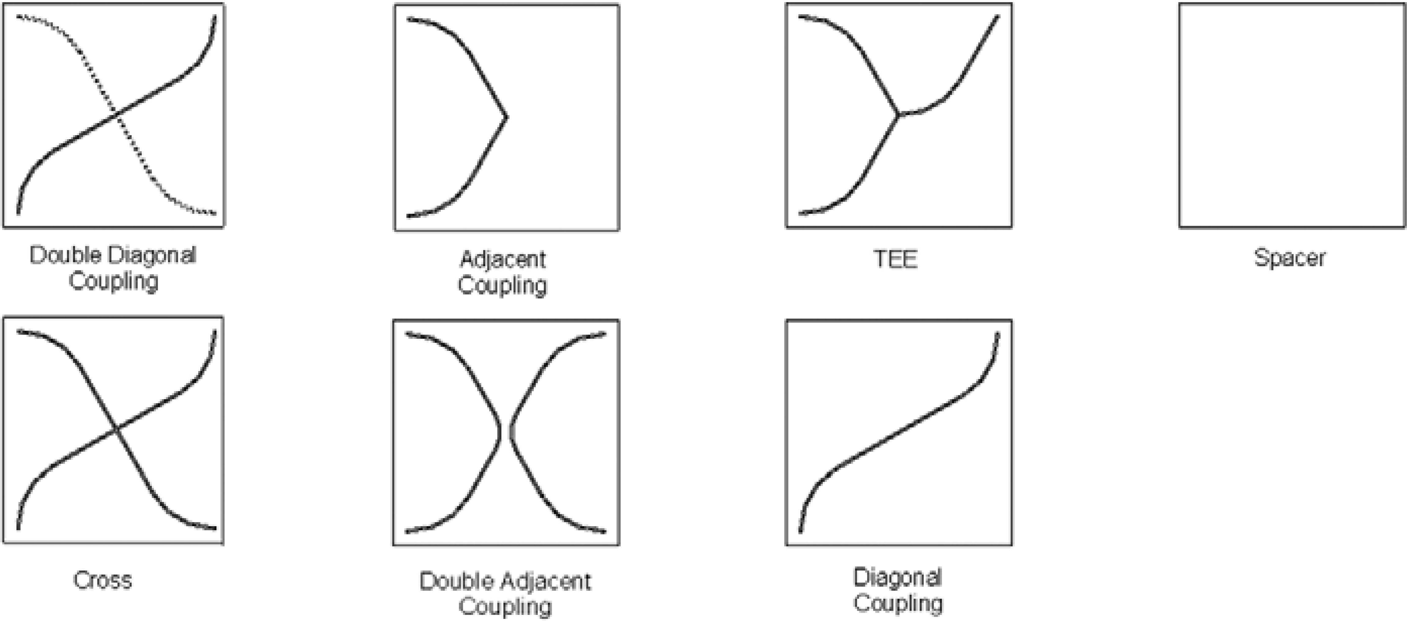
LabMatrix™ logic patterns.
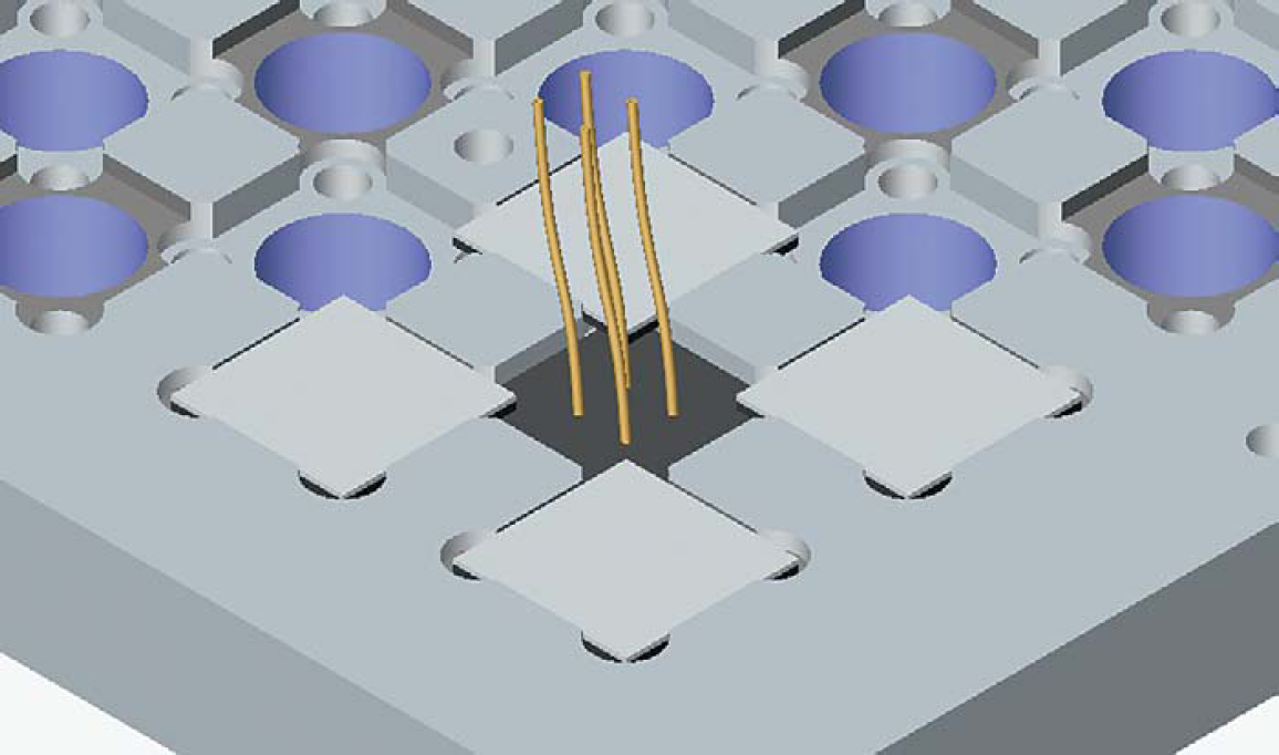
The functional chips, in addition to their ability to carry out specific tasks, are designed and produced with a series of structural variations that provide the user with the “tools” necessary to systematically explore the effects of the chip's microstructural variations on its overall performance. For example, researchers worldwide have tested microfluidic channels populated with columns (Figure 5) for the purpose of electrophoretic and/or chromatographic separation, particle capture, or enzymatic reactions. Experimental data have revealed that some remarkable phenomena observed by researchers are closely related to the high regularity of microfeatures inside the channel. However, the effort to fully explore the application potential of these features is hampered by the lack of a commercial source for chips whose columns vary in shape, size, and arrangement. By using a set of chips that accomplish these variations and the LabMatrix™ platform, researchers are positioned to fully investigate these structural/performance relationships with few experimental restrictions.
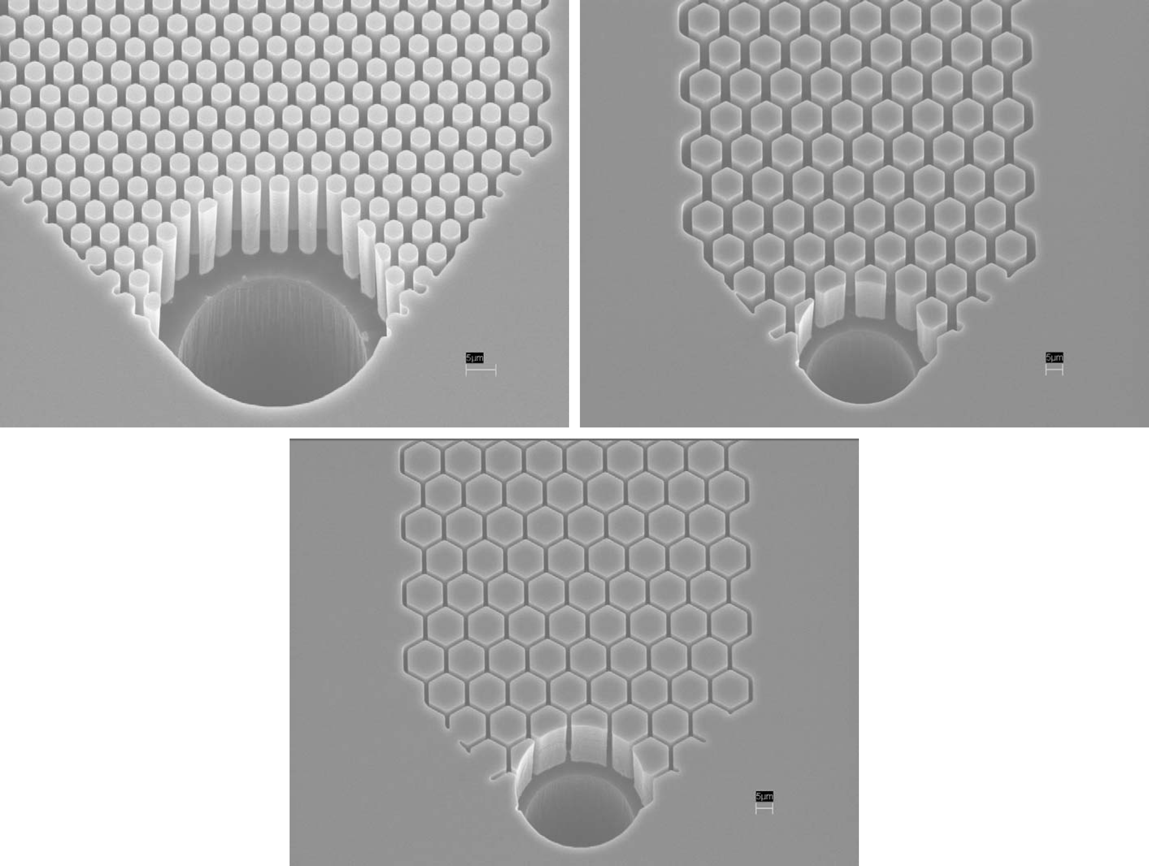
Chips with columns of different spacings, sizes, and surface/volume ratios provide the researcher with variables to study separation phenomena.
After fabrication, all LabMatrix™ chips are treated at high temperature to form a thin layer of quartz (fused silica) on the surface of the chip that provides hydrophilicity and chemical inertness. The hydroxyl groups on the quartz surface are amenable to conversion into a wide range of other functional groups such as amine or aldehyde, with or without any tethering molecules. All of these modifications can be carried out using well-known surface chemistry. It is, therefore, a straightforward practice for researchers to attach macromolecules or other agents of interest to the chip's surface for affinity-based separations or other applications.
Versatile and Reusable Fluid Network
To create a reconfigurable and reusable fluid network comprised of numerous miniaturized joints, the system requires a suitable sealing technique to prevent leakage. These seals would preferably feature low swept volume, adequate material conformality, minimal assembly time, and reusability. Additionally, the sealing materials must withstand a wide range of organic solvents and inorganic buffers at elevated temperature. The LabMatrix™ system utilizes a proprietary, form-in-place o-ring sealing technique to meet these demands (Figure 6). This technique, when used to form chip-to-chip seals, results in extremely small void volume (∼12 nL). Additionally, the micro o-rings show no observable effect when tested against alcohols, ketones, halogenated hydrocarbons, amines, and acids. The seal readily holds up to 80 psi with only a modest compressive force.
Form-in-place sealing provides fluid communications between chips.
Previous microfluidic breadboard concepts incorporated prefabricated fluidic channels into the body of the board to define the fluid path from chip-to-chip. An inherent drawback of this approach is that these prefabricated channels dictate the fluid network structure and limit the flexibility of the system. In contrast, the LabMatrix™ system's design, with overlapping chip corners and on-chip micro o-rings, provides users with complete freedom in chip-level network configuration and fluid-network reusability (Figure 7).
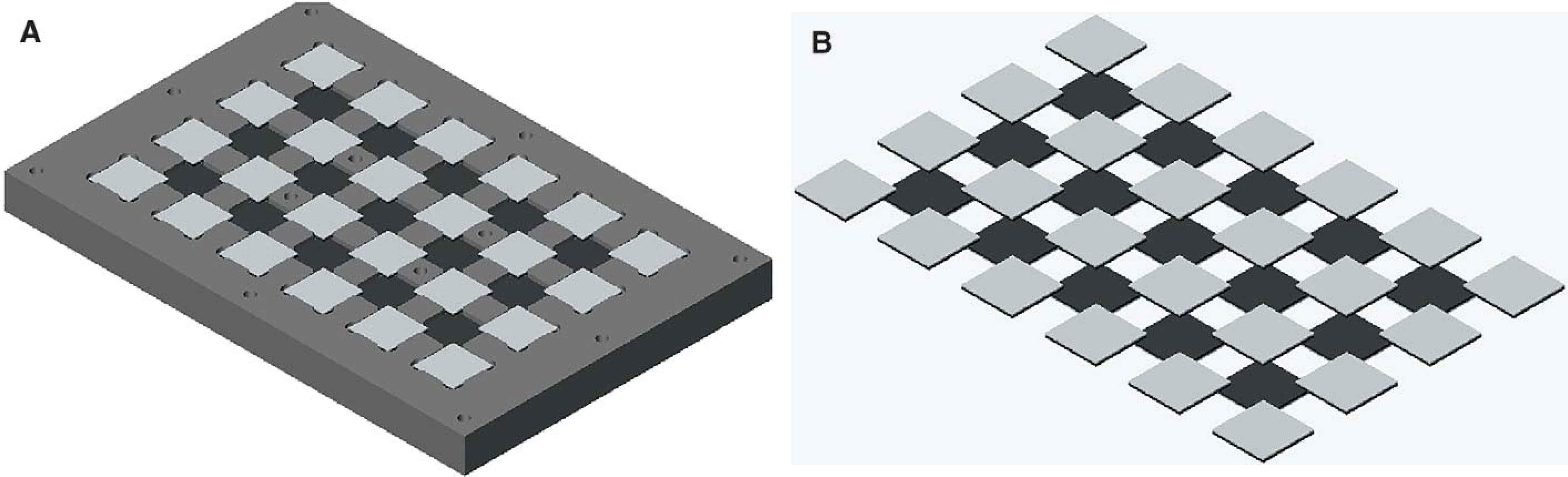
(A) A fluid network is formed by placing chips in the alignment pockets on the breadboard. (B) View of the fluid network apart from the breadboard.
The corner alignment design modularizes the entire fluid network on the breadboard. This permits the user, upon completion of a single experiment, to remove, replace, or reposition any network component(s) with minimal disturbance to surrounding components in the system. The formation of flexible fluid networks and the freedom to replace individual chips provide maximum system versatility and reconfigurability with minimal assembly effort.
NanoFlow Cell for UV Detection
One of the design goals of the LabMatrix™ system was to provide the user with a complete solution for “proof-of-concept” work with minimum integration effort. To achieve this goal, Kionix developed the NanoFlow cell (Figure 8), a standard component of the LabMatrix™ system used for UV detection. The NanoFlow cell features a small swept volume of 50 nL and accepts standard fiberoptic fittings. It permits repetitive, quick, and reliable connections to a UV spectrometer and a light source. In contrast to traditional capillary in-line UV detection, which suffers from limited path length due to the capillary inner diameter, the micromachined NanoFlow cell allows sophisticated design control over the shape, size, and path length of the detecting channel to maximize the overall detection sensitivity.
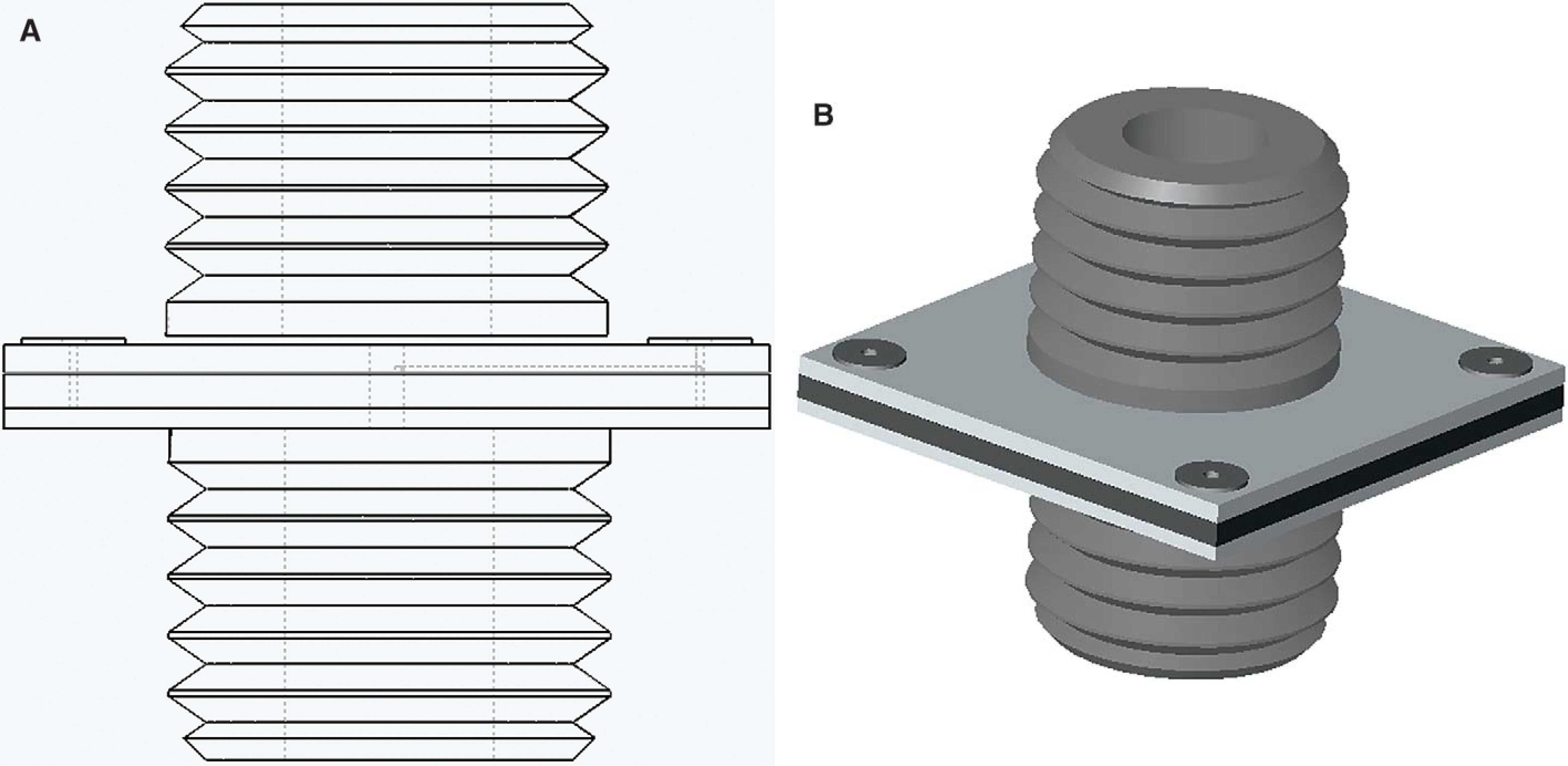
(A) Side view and (B) isometric view of a UV flow cell for LabMatrix™. The flow cell features small void volume and sufficient UV light path length.
The light source and spectrometer used with the Lab-Matrix™ allow eight detecting channels to be recorded simultaneously. The data can be acquired as three-dimensional spectra, similar to a photodiode array detector used with an HPLC system or two-dimensional chromatographs (Figure 9). Integrated software for the control of a fluid delivery device, such as a syringe pump, and the multichannel UV detecting system is provided with the LabMatrix™ system.
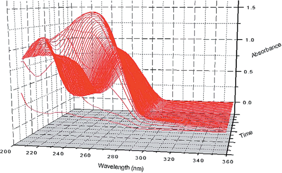
A three-dimensional spectrum of a compound dissolution experiment performed on the LabMatrix™ system.
Capillary Chip
The creation of a modular, reconfigurable, and reusable microfluidic prototyping system must overcome two main hurdles: The first is to establish a two-dimensional fluid network. The second is the ability to interface that fluid network to an external device such as a syringe pump. The design of the LabMatrix™ microfluidic breadboard addresses both of these challenges. The corner-overlapped chips, situated in deep and shallow pockets, allow a user to rapidly assemble a microfluidic network. Prefabricated threads in the breadboard, located at the corner of each chip, provide fluid ingress/egress by means of microfittings. The user can simply tighten a microfitting to seal a capillary against a fluid access port at any location. This design eliminates the tedious and time-consuming task of epoxying individual microfitting assemblies to each chip, and it significantly reduces the size of the chip and its cost.
The LabMatrix™ system also includes a group of prefabricated capillary chips (Figure 10) as an alternative to the microfittings for fluid ingress/egress. These chips share the same footprint as other LabMatrix™ chips and contain from one to four fluid communication ports. Every port is independently connected to a capillary located at the center of the chip. Whenever a fluid connection is desired between the fluid network on the breadboard and an external device, the user can simply place a capillary chip at the appropriate location. Upon completion of the breadboard assembly, the user can connect the capillary directly, or through a quick-connect union, to an external device. The capillary chips add an additional degree of reliability and operational flexibility to the “tool box” of connections in the LabMatrix™ system.
The LabMatrix™ provides a group of capillary chips for fluid ingress/egress. Using these chips with micro quick-connectors, users can rapidly establish fluid connections within minutes without adhesives.
Summary
The LabMatrix™ system is the only microfluidic product designed with maximum flexibility in mind, providing the user with a means to prototype a wide range of microfluidic applications in a short period. It features a microfluidic breadboard for the formation of reconfigurable application-specific fluid networks; fluid logic and functional chips for fluid network flexibility; and the NanoFlow cell for integrated molecular detection. The LabMatrix™ system enables multiple microfluidic applications to be simultaneously exercised. In addition, the open fluid access feature of the system allows the user to smoothly integrate existing application development efforts into the LabMatrix™ platform.