
Abstract
Cell spheroids are multicellular aggregates, grown in vitro, that mimic the three-dimensional morphology of physiological tissues. Although there are numerous benefits to using spheroids in cell-based assays, the adoption of spheroids in routine biomedical research has been limited, in part, by the tedious workflow associated with spheroid formation and analysis. Here we describe a digital microfluidic platform that has been developed to automate liquid-handling protocols for the formation, maintenance, and analysis of multicellular spheroids in hanging drop culture. We show that droplets of liquid can be added to and extracted from through-holes, or “wells,” and fabricated in the bottom plate of a digital microfluidic device, enabling the formation and assaying of hanging drops. Using this digital microfluidic platform, spheroids of mouse mesenchymal stem cells were formed and maintained in situ for 72 h, exhibiting good viability (>90%) and size uniformity (% coefficient of variation <10% intraexperiment, <20% interexperiment). A proof-of-principle drug screen was performed on human colorectal adenocarcinoma spheroids to demonstrate the ability to recapitulate physiologically relevant phenomena such as insulin-induced drug resistance. With automatable and flexible liquid handling, and a wide range of in situ sample preparation and analysis capabilities, the digital microfluidic platform provides a viable tool for automating cell spheroid culture and analysis.
Introduction
Cell spheroids are multicellular compact aggregates, grown in vitro, that have a three-dimensional (3D), spherical morphology. Unlike cells grown in two-dimensional adherent monolayers, cells grown in three dimensions possess a high degree of intercellular interactions and exhibit relatively complex nutrient and metabolic mass transport gradients. These lead to cellular heterogeneity within the 3D aggregate and to gene and protein expression patterns that more closely mimic in vivo tissues.1–6 The differential expression profiles result in significant differences in cellular behaviors such as drug sensitivity, differentiation capacity, malignancy, function, and viability. For example, hepatocellular carcinoma cells grown as spheroids exhibit more physiologically relevant levels of cytochrome P450 activity and albumin secretion compared with cells grown in monolayers. 7 Another example is mammary epithelial cells, which exhibit basement membrane-induced apoptosis resistance when grown in three dimensions but are susceptible to apoptosis in monolayer culture. 8 Because of their enhanced physiological relevance compared with monolayer cell cultures, cell spheroids can provide more accurate models for cell-based assays and screens. Improved tissue and disease models not only enhance basic research but can be extremely valuable in commercial research, particularly in the pharmaceutical industry, where the failure rates for drug candidates entering clinical trials are typically >80%.9–13
Despite the known advantages of 3D cell cultures, their use in cell-based assays and screens has been limited. It is estimated that <30% of cancer and molecular biologists use 3D cell culture and that <20% of drug leads generated by the pharmaceutical industry are developed through cell-based phenotypic assays.14,15 A major reason for the relatively low adoption of 3D cell models is the limited number of user-friendly, flexible, and automated methods for performing spheroid culture and analysis.16,17 Although a variety of technologies and methods are available for culturing 3D micro tissues, each approach has limitations that make it unsuitable for routine assays and screens. 18 Nonautomated spheroid culture methods, such as the manual hanging-drop technique or the use of micro molds, are inexpensive and relatively simple, but interrogating individual spheroids requires manual transfer to a separate vessel. In addition, the nonautomated methods often require a significant amount of manual sample handling, which can be tedious, time-consuming, and prone to variability and error.
A number of microfluidic techniques for spheroid culture have been developed that can enable high-throughput and massively parallel spheroid formation but that do not support the interrogation of spheroids individually on the same device.19–22 Rotary vessels and spinner flasks can also be used to generate a large number of spheroids but provide limited control over spheroid size and also do not allow for in situ assaying of individual spheroids. Alternatively, specially engineered well plates, such as those capable of supporting hanging drop culture 23 or those with nonadhesive surfaces designed to induce cell aggregation, 24 are compatible with robotic liquid-handling equipment, enabling automation and high-throughput processing. However, the ability to automate spheroid culture and analysis using these methods requires access to robotic liquid-handling equipment, which can be prohibitively expensive to acquire, operate, and maintain for many research labs, particularly those in academic settings in which the emphasis may not be on high-throughput experiments. In addition, functionalities necessary for spheroid culture and analysis, such as in situ microscopy, mixing, and temperature control, require additional, often expensive, hardware to be added to the liquid-handling instrument. Thus, there is a need for a spheroid culture and analysis technology that provides some of the advantages of automation, in a platform that is more accessible than current automated methods. We propose that digital microfluidics (DµF), a flexible and precise microfluidic liquid-handling technology, can be used to automate cell spheroid culture and analysis as well as provide some unique benefits over existing automated techniques.
Digital microfluidics is a type of microfluidic platform that enables the manipulation of discrete droplets of liquid in either an air or liquid ambient medium through the spatially and temporally controlled application of electric fields.25–27 The application of an electric potential across the solid-liquid contact line generates a combination of electrostatic and/or dielectrophoretic forces, depending on the frequency of the applied field and the relative permittivities of the liquid and ambient phases. Sequentially applying an electric potential to an array of planar electrodes can enable the translation of droplets across the array 28 and can also be used to split, merge, and mix droplets.
Here we present a digital microfluidic device that enables the formation of hanging drops to allow in situ cell spheroid culture. With the ability to automate liquid handling, and with a wide range of in situ bioanalytical techniques developed for the DµF platform, DµF can ultimately provide a powerful tool for automation of spheroid-based assays and screens.
Materials and Methods
Bone marrow–derived mouse mesenchymal stem cells (ATCC CRL-12424) were generously donated by Professor Tatiana Segura (University of California, Los Angeles [UCLA]). HT-29, human colorectal adenocarcinoma cells (ATCC HTB-38), and BJ human foreskin fibroblasts (ATCC CRL-2522) were purchased from ATCC. Leibovitz L-15 cell culture medium, Dulbecco’s Modified Eagle Medium (DMEM), penicillin-streptomycin (P/S) solution (10,000 U penicillin, 10 mg streptomycin/mL), L-glutamine, fetal bovine serum (FBS), and the LIVE/DEAD Viability/Cytotoxicity Kit for mammalian cells were obtained from Life Technologies (Carlsbad, CA). Pluronic F-68 was purchased from Sigma (St. Louis, MO). Cytop (CTL-809M) and CYSOLV-180 were purchased from Bellex International Corporation (Wilmington, DE). Human recombinant insulin was purchased from R&D Systems, Inc. (Minneapolis, MN), and Irinotecan HCL was purchased from BIOTANG, Inc. (Lexington, MA).
Device fabrication was conducted in the California NanoSystems Institute (CNSI) Integrated System Nanofabrication Cleanroom at UCLA. Briefly, water white glass substrates (LabScientific, Inc., Livingston, NJ; cat No. 7787) were coated with 1100 Å indium tin oxide (ITO) via sputtering and were patterned with electrodes via photolithography and reactive ion etching. For this work, the substrate with the patterned electrode array was used as the top plate, and an unpatterned ITO-coated slide was used as the bottom plate. Prior to coating with the dielectric, through-holes were manually drilled into specific locations on the bottom plate using a benchtop drill press and diamond-coated drill bits. Through-holes were also drilled into the footprint of the reservoir electrodes in the top plate to provide a world-to-chip interface. The top plates were then coated with 3 to 4 µm of dielectric polymer parylene-C (Specialty Coating Systems, Indianapolis, IN) by vapor deposition. The top and bottom plates were rendered hydrophobic by spin coating ~300 to 400 nm of Cytop on each. Prior to use, the walls of the wells in the bottom plate were gently scraped with a diamond-coated drill bit to remove the Cytop coating and expose the hydrophilic glass surface. A schematic of a DµF device assembly is shown in Figure 1 .
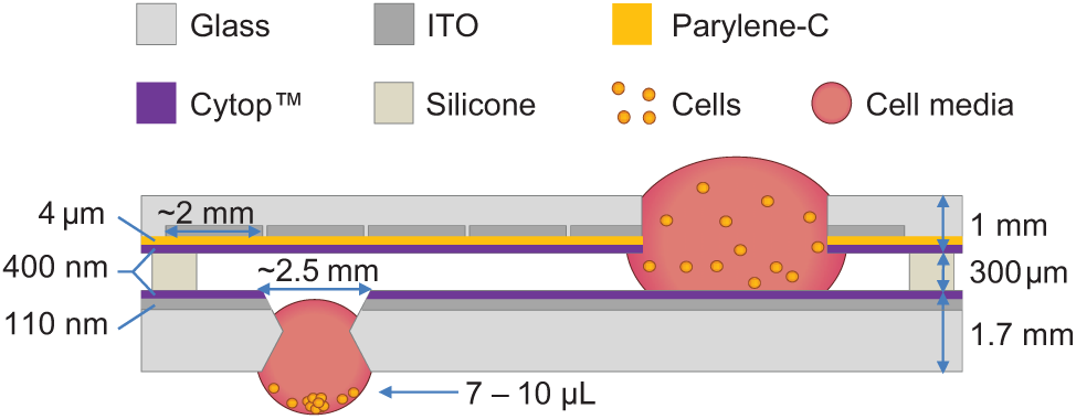
Device schematic and dimensions. Through-holes in the top plate allow for the addition of solutions to on-chip reservoirs, whereas through-holes, or “wells,” in the bottom plate allow for the formation of hanging drops. Drops that are delivered to a well are drawn into the well spontaneously upon contact with the hydrophilic well wall. Addition of multiple drops to a well allows for the formation of a hanging drop with a curved air-liquid interface. Cells suspended in the drop can aggregate at this interface, forming a single spheroid within the drop.
All microfluidic liquid handling was performed using a custom LabView application to control electrode actuation. Liquid handling was performed at 100 to 115 Vpp AC and at a frequency of 18.5 kHz. Analysis of hanging droplet liquid exchange was performed by measuring the absorption of a standardized solution of brilliant blue dye prepared in water before and after liquid exchange cycles using a Thermo Scientific NanoDrop 2000c UV-Vis spectrophotometer. The liquid exchange process is described in more detail below.
For the preparation of cell solutions for use on the DµF device, cells were thawed and seeded in polystyrene dishes in growth medium (DMEM, 4 mM L-glutamine, 10% FBS, 100 U/mL P/S solution). Cells were grown to ~80% confluency, trypsinized, and resuspended in spheroid growth medium (Leibovitz L-15 medium, 4 mM L-glutamine, 7.5% FBS, 100 U/mL P/S, 0.04% Pluronic F-68) at cell densities ranging from ~7.5e5 to 1e6 cells/mL for culture on the device.
Detailed schematics of the experimental setup, as used in this work, are shown in
Hanging drop and spheroid formation were achieved by dispensing droplets of cell suspension from the reservoir and moving the droplets to the location of a well. Upon contact with the hydrophilic wall of the well, droplets were pulled into the well via capillary forces. Addition of multiple droplets to a well resulted in the formation of a hanging drop. Exchange of the medium within the hanging drop was achieved by performing the following sequence of steps one or more times per well: (1) delivering a drop of fresh medium to a well, (2) using electrowetting actuation to repeatedly pull out and release a liquid finger from the well to facilitate mixing of the liquid in the well, (3) extracting a drop from the well of twice the volume of the amount initially delivered, and (4) adding another drop of fresh medium to the well. Devices were kept in an incubator at 37 °C and 95% relative humidity at all times except during liquid handling.
For confocal imaging, spheroids were stained with fluorescent markers by incubation in imaging medium for 2 h at 4 °C followed by 30 min at 37 °C to ensure enhanced staining of the interior of the spheroid.
29
The imaging medium consisted of 2 µM calcein-am and 4 µM ethidium homodimer-1 (LIVE/DEAD Viability/Cytotoxicity Kit, for mammalian cells; Life Technologies) in Hank’s Balanced Salt Solution (HBSS; Life Technologies) supplemented with 1 mg/mL ascorbic acid, 25 mM HEPES buffer solution (pH 7), 100 U/mL P/S, 100 µM nonessential amino acids, and 4 mM L-glutamine; 1 N NaOH was used to adjust the pH to 7.2. Following staining with imaging medium, the spheroids were washed with HBSS containing 1 mg/mL ascorbic acid. A custom polydimethylsiloxane (PDMS) imaging chamber was secured beneath the bottom plate such that flooding the wells with the HBSS solution caused the hanging drops to detach from the device into individual wells within the PDMS chamber, enabling the spheroids to be imaged directly from the device.
Confocal imaging was performed using a Leica TCS SP2 confocal microscope. Spheroid images were constructed by creating a maximum projection of multiple z-plane sections spaced 3 to 7 µm apart. The proportion of living cells within a spheroid was estimated by counting the number of live (green) and dead (red) cells in five different, equally spaced z-planes throughout the spheroid. ImageJ was used for all image analyses, which included hanging drop volume as well as spheroid viability, diameter, and aspect ratio measurements.
Results and Discussion
Device Design and Operation
To enable hanging drop formation, through-holes, or wells, were fabricated into strategic locations in the bottom plate of the device. The schematic in Figure 1 shows the basic principle of DµF hanging drop formation along with typical device dimensions. Hanging drops are formed when droplets of liquid are delivered to the location of a well and, upon making contact with the hydrophilic walls of the well, get pulled into the well spontaneously via capillary forces ( Fig. 2a ). Adding multiple drops to a well results in the formation of a curved liquid-air interface that protrudes beneath the bottom plate, similar to a hanging drop ( Fig. 2b ). To ensure the formation of a hanging drop, the wells were designed such that the Bond number (Bo, a dimensionless parameter describing the ratio of gravitational to surface tension forces) of the system is greater than ~0.3, which is within the range in which gravitational forces begin to influence the shape of the meniscus.30–32 A Bo ≥0.3 requires a well diameter of ≥2.4 mm.
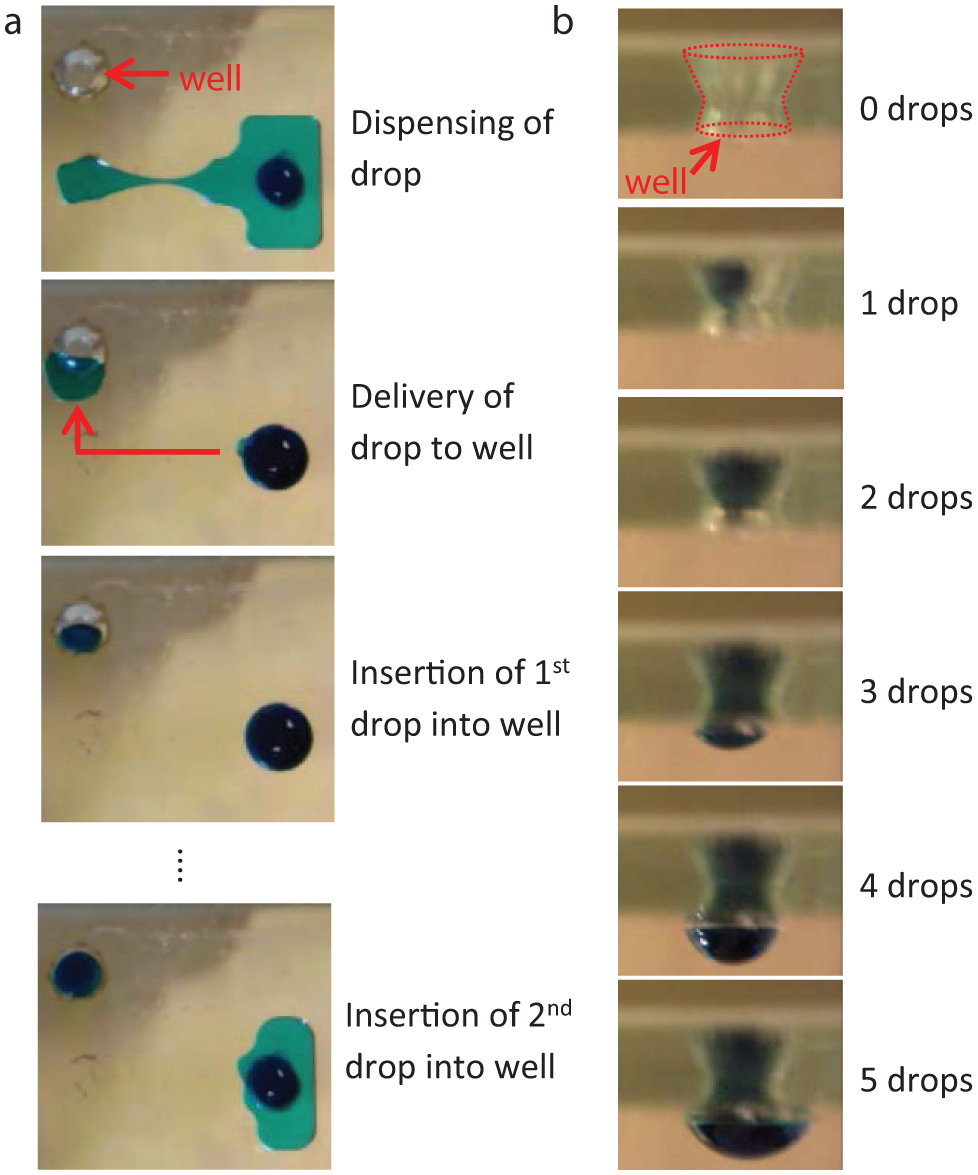
Hanging drop formation on a digital microfluidic device. (
To simplify device fabrication protocols, the top plate contained the actuating electrodes and the bottom plate contained the ground electrode. Although either the actuating or ground plate can be modified with through-holes and used as the bottom plate to support hanging drop formation, we found that incorporating the wells into the plate containing the actuating electrodes was more difficult because the holes needed to be drilled precisely within the footprint of an electrode, which occasionally resulted in damaging the electrode. In addition, decoupling the wells and actuating electrodes allows for the actuating top plate to be removed and replaced in the case of dielectric breakdown, without disrupting the hanging drops in the wells in the bottom plate.
Dielectric breakdown occurs when the electric field across the dielectric layer exceeds the dielectric strength of the material, resulting in localized, physical destruction of the dielectric layer. Dielectric breakdown typically occurs on the actuating plate, where charges within the drop and electric field lines outside the drop concentrate near the droplet edge closest to the actuated electrode, creating a region of locally elevated electric field strength.33–35 If the degree of dielectric breakdown is minor, droplets can still be transported normally across the location of the breakdown. Significant dielectric breakdown can cause electrolysis of aqueous solutions as a result of the current flow into the drop and can also damage critical electronic connections on the device, thereby impeding droplet movement (“pinning”). For the top plates used in this work, the entire spheroid culture process, which required ~800 to 1200 total electrode actuation steps for the culture of six to eight spheroids, could typically be achieved without the occurrence of dielectric breakdown. Approximately 1 of every 4 devices showed evidence of dielectric breakdown at some point during the culture protocol, typically during the 48 h medium exchange process (i.e., after the hanging drops had been formed and all the cell handling had been completed). Because the spheroids were maintained in hanging drops beneath the bottom plate and were relatively far from either of the interior surfaces of the top and bottom plates, dielectric breakdown did not disrupt or affect the spheroids within the hanging drops.
To allow visualization of droplet handling, the actuating electrodes in the top plate were made from a transparent conductive material, ITO. Videos of liquid handling and hanging drop formation are provided in the Electronic Supplemental Information.
The wells in the bottom plate contain a tapered opening on the top side to aid in the insertion of drops into the well. Droplets that reach the edge of a well can experience canthotaxis, or pinning, at the intersection of two interfaces, due to both the change in geometry at the well edge and the difference in surface properties between the hydrophobic surface of the bottom plate and the hydrophilic interior of the well walls. By tapering the inside walls of the well to form an acute angle with the surface of the bottom plate, as opposed to a right angle formed by a cylindrical through-hole, the pinning effect on a drop of liquid at the edge of the well is reduced, facilitating droplet insertion into the well.
The volume of a hanging drop is determined by the number of drops dispensed from a reservoir and added to a well. Thus, the volume and reproducibility of droplet dispensing from the reservoirs are critical to the volume and reproducibility of the hanging drops. To determine the variation in dispensed drop volumes, we used image analysis to measure the volumes of 144 drops of an aqueous surfactant solution (0.04% Pluronic F-68) dispensed from different reservoirs across three different devices using a programmed dispensing sequence. An aqueous surfactant solution was used so that the surface tension of the liquid and, consequently, the volume of the dispensed drops would be similar to that of the growth medium solution subsequently used in the cell culture experiments, which also contained 0.04% Pluronic F-68. The dispensed droplet volume was determined by measuring the area of the drop in contact with the top plate using device features of known dimensions as a scale and multiplying by the known distance of the interplate gap. Although in actuality, the sidewalls of the droplet are curved, to simplify the volume measurements we used the straight wall, cylindrical approximation to calculate droplet volumes, which is a reasonable approximation considering the relatively small droplet aspect ratio on our devices (h/w ~0.15) and the contact angle of approximately 100°. 36 The distribution of droplet volume measurements is shown in Figure 3 . The average volume of a single dispensed drop was 1.75 ± 0.13 µL (7.7% coefficient of variance [CV]). This degree of droplet volume variation is consistent with reproducibility values from other electrowetting devices that do not use capacitance metering to control dispensing volumes. Droplet dispensing reproducibility can be improved to low single-digit %CV by employing capacitance metering methods or by optimizing reservoir and dispensing electrode design.37–39 The variation in the volumes of hanging drops was also determined ( Fig. 4 ). Hanging drops formed from four, five, and six dispensed drops had average volumes of 7.4 ± 0.5 µL, 8.8 ± 0.8 µL, and 10.2 ± 0.5 µL, respectively, corresponding to %CV range of 5% to 9%. This volume range was chosen because, for the devices used in this work, at least four drops are required to fill a well and form the curved surface necessary for cell aggregation.
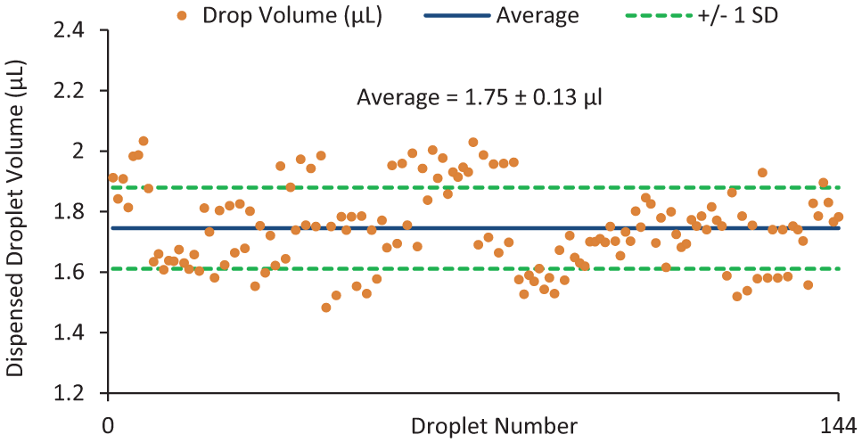
Distribution of dispensed drop volumes. A total of 144 drops were dispensed from different reservoirs across three different devices using a preprogrammed droplet-dispensing sequence. The average drop volume was 1.75 µL and the percentage coefficient of variation of the volume of all drops dispensed was ~8%.
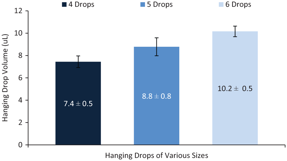
Size and variation of hanging drop volumes. Hanging drops comprised of four, five, and six dispensed drops had volumes of 7.4 ± 0.5 µL, 8.8 ± 0.8 µL, and 10.2 ± 0.5 µL, respectively (N = 8 hanging drops formed for each condition). For each condition, the variation in hanging drop volume was <10%. Hanging drops of volumes up to ~55 µL can be formed on the devices used in this work; however, only 7 to 10 µL is needed to form cell spheroids via the hanging drop technique.
It should be noted that the volume and reproducibility data shown here represent results from a particular dispensing sequence and device arrangement (i.e., gap height = 300 µm). Various droplet volumes can be dispensed on a DµF device by simply altering the gap height and/or changing the dispensing sequence. The devices used in this work support the formation of hanging drops up to ~55 µL before the drops detach from the well due to their weight. We observed that hanging drops of larger volumes can be supported by varying the thickness of the bottom plate, the well geometry, or the surface tension of the liquid comprising the drop (determined experimentally, data not shown).
Cell spheroids require ~50% medium exchange every 48 h for optimal growth.40,41 Thus, to enable long-term hanging drop spheroid culture, protocols for in situ medium exchange using digital microfluidic liquid handling were developed. Medium exchange requires extracting the spent medium from a hanging drop and replacing the spent medium with fresh medium. Liquid can be extracted from a hanging drop by using the electrodes adjacent to a well to pull out a drop of liquid. Repeating the process of extracting and adding drops of medium to a well, as described in the Materials and Methods section, results in the exchange of the medium within the well. Assuming the hanging drop initially contains the volume of four dispensed drops, the medium exchange protocol theoretically allows for exchange of 40% and 64% of the initial drop volume after one and two exchange cycles, respectively (according to the dilution rate for this particular exchange protocol: C = 0.6n, where C = the concentration of spent medium in the drop, and n = the number of exchange cycles). The video “Hanging Drop Liquid Exchange” in the Electronic Supplemental Information shows two cycles of the liquid exchange protocol. Using a hanging drop of a standardized brilliant blue dye solution to mimic spent medium and deionized water to represent fresh medium, we assessed the degree of exchange by measuring the change in dye concentration of the hanging drop after successive exchange cycles by visible spectrophotometry. Figure 5 shows that the dye concentration calculated from UV-Vis absorption is consistent with the theoretical predictions, indicating that >50% medium exchange can be achieved with one or more exchange cycles. These data also indicate that DµF can provide precise control over the composition of the hanging drop, which is critical for performing cell-based assays and screens.
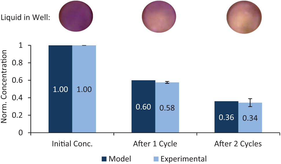
Extent of liquid exchange, predicted and experimental results. The extent of liquid exchange after one and two exchange cycles was monitored by measuring the change in absorbance of the dyed hanging drop solution and calculating the concentration from a standard curve. The dilution of a hanging drop after each cycle can be seen in the images above the plot. The agreement between the measured concentrations and the predicted values indicates that thorough mixing of the hanging drop is achieved during each exchange cycle and that DµF provides good control over the composition of the hanging drop. Error bars indicate the standard deviation of measurements from three different experiments.
Cell Spheroid Culture
After establishing the ability to form a hanging drop and conduct medium exchange, a complete cell spheroid culture protocol was performed to demonstrate proof of principle for fully automated DµF cell spheroid culture. Droplets of mouse MSC suspension in growth medium were delivered to wells to form hanging drops of ~7 to 10 µL (~5250–7500 cells/drop). Pluronic F-68 was included in the growth medium to minimize the adsorption of proteins to the hydrophobic surface of the device, which can impede the movement of proteinaceous solutions. 42 At 0.04%, Pluronic F-68 is known to be noncytotoxic. 43 Leibovitz L-15 medium was used for spheroid culture because it is buffered by phosphates and free-base amino acids instead of sodium bicarbonate. This medium allows cell growth in the absence of a controlled CO2 atmosphere; our current digital microfluidic setup is operated outside of an incubator at ambient atmospheric conditions. During liquid handling, the microfluidic apparatus was kept at ~37 °C by placing a thin-film polyimide heater in contact with the aluminium device holder. After liquid handling, devices were transferred to an incubator at 37 °C and relative humidity of 95%. To prevent fluctuations in atmospheric conditions between the liquid-handling and incubation periods, the incubator was also maintained at ambient atmosphere (i.e., without CO2 control).
Medium exchange was performed once daily. During culture, the spheroid sits at the bottom of the hanging drop, which is ~1.8 mm below the top opening of the well (assuming a 7.4 µL drop in a 2.5-mm diameter well). Because liquid from the drop is extracted from the top opening of the well and medium exchange never requires extraction of more than 25% of the initial hanging drop volume, the spheroid remains settled within the hanging drop throughout the medium exchange protocol and does not get extracted from the well.
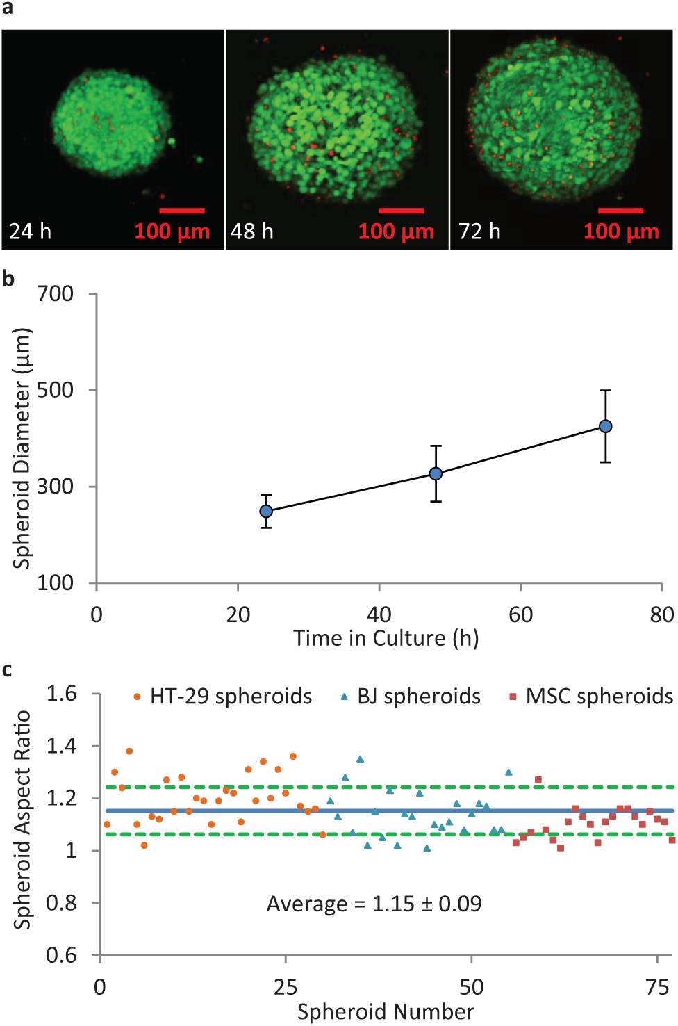
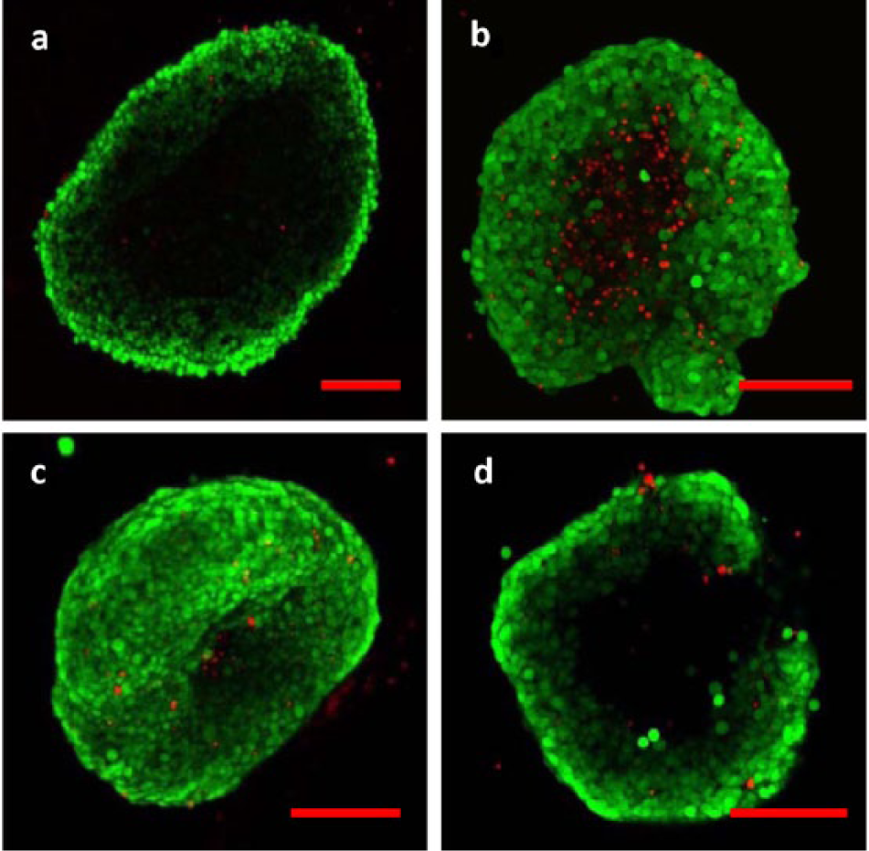
Figure 6a shows confocal micrographs of typical spheroids of mouse mesenchymal stem cells cultured on the DµF device over the course of 72 h using automated sample handling protocols. The spheroids were stained with calcein-AM and ethidium homodimer-1 to indicate living (green) and dead (red) cells, respectively. Counting the number of living and dead cells at various z-planes within the spheroid indicated that the spheroids exhibited >90% cell viability. The spheroid diameter was measured at 24, 48, and 72 h ( Fig. 6b ) following hanging drop formation using a USB microscope (Dino-Light AD4013TL). A seeding density of 7.5e5 cells/mL produced spheroids of up to ~400 µm after 72 h in culture. The size and viability of the spheroids generated on the DµF platform are consistent with those obtained through other hanging drop techniques over the same time frame using similar cell number conditions. 23 Intradevice spheroid diameter variation was ~8%; this is comparable to other hanging drop techniques, which exhibit a %CV range of ~3% (for robotic liquid handlers) to 15% (for manual methods), and is superior to spheroid generation on nonadhesive flat-bottom well plates, which show spheroid diameter variation of up to 40% to 60%.44,45 Because the cell density is the same for each hanging drop, the intraexperiment spheroid diameter variation is attributable to the variation in the volumes of the hanging drops. The interdevice variation in spheroid diameter (i.e., for spheroids grown on different devices) was 14%, 18%, and 18% for spheroids at 24, 48, and 72 h, respectively ( Fig. 6b ). The relatively larger interexperiment variation compared with the intraexperiment results is likely due to variations in cell densities between the different experiments. For this work, cell suspensions of ~7.5e5 cells/mL were prepared based on hemocytometer measurements, which can exhibit variability of 10% to 40% depending on cell concentration.46,47 More precise cell-density measurement techniques, which can achieve a %CV of <3%, 48 would reduce the interexperiment spheroid diameter variability. Figure 6c shows the distribution in spheroid aspect ratio (ratio of spheroid major axis to minor axis) for 77 spheroids of various cell numbers and types. The average aspect ratio for the spheroids cultured on the DµF platform was 1.15 ± 0.09, corresponding to a CV of ~8%. The spheroid aspect ratio was measured after at least 48 h in culture to allow spheroid compaction to occur. Table 1 summarizes performance characteristics for spheroid culture conducted on a DµF device.
Cell spheroids formed by DµF hanging drop culture. (
Performance Characteristics of Devices Used in This Work.
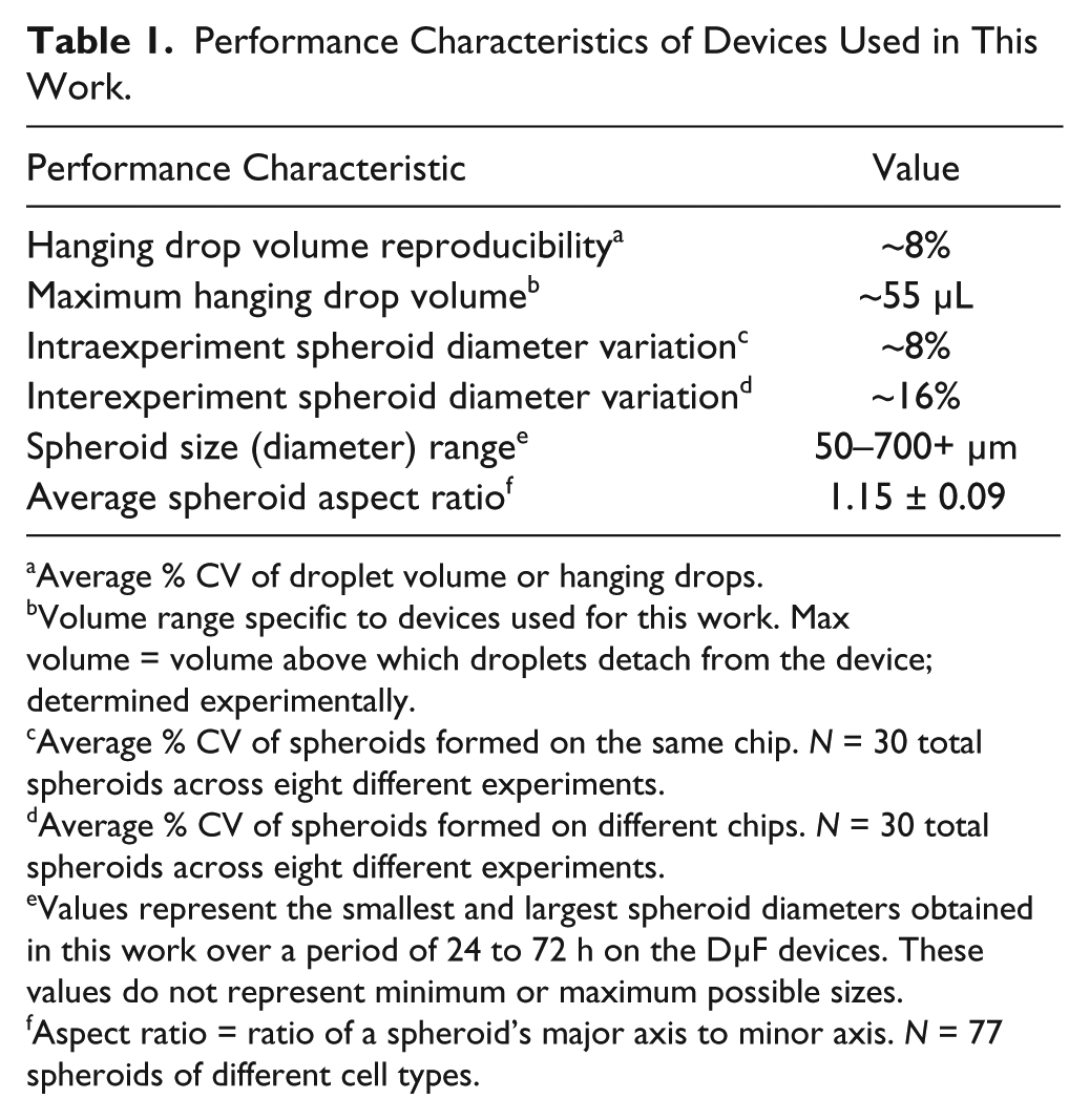
Average % CV of droplet volume or hanging drops.
Volume range specific to devices used for this work. Max volume = volume above which droplets detach from the device; determined experimentally.
Average % CV of spheroids formed on the same chip. N = 30 total spheroids across eight different experiments.
Average % CV of spheroids formed on different chips. N = 30 total spheroids across eight different experiments.
Values represent the smallest and largest spheroid diameters obtained in this work over a period of 24 to 72 h on the DµF devices. These values do not represent minimum or maximum possible sizes.
Aspect ratio = ratio of a spheroid’s major axis to minor axis. N = 77 spheroids of different cell types.
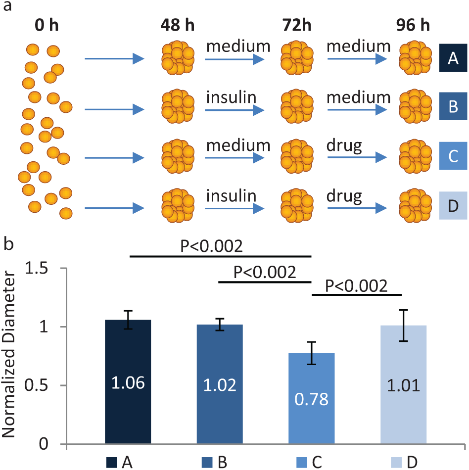
With the ability to initiate and maintain viable spheroids in culture as well as freely add, mix, and extract liquid from a hanging drop, the DµF platform enables automation of spheroid-based assays and screens. To demonstrate this capability, we performed a proof-of-principle spheroid-based drug screen, using DµF to examine the impact of insulin exposure on the chemosensitivity of colon cancer cells to treatment with the chemotherapeutic agent irinotecan. Insulin has been shown to cause resistance to chemotherapy in certain colon cancer cell lines via activation of the PI3K/Akt pathway.49,50 For the drug screening assay, hanging drops of HT-29 human colon adenocarcinoma cells were initiated and maintained on a DµF device for 48 h to allow for the formation of compact spheroids. After 48 h of culture, the medium for some spheroids was exchanged for medium containing 500 nM insulin, whereas the remaining spheroids received normal growth medium. The insulin-induced drug resistance effect has been observed in HT-29 cells in vitro at insulin doses of 100 to 1000 nM.50,51 Spheroids were allowed to incubate in their respective medium for 24 h, after which the medium was exchanged for medium containing 100 µM irinotecan, or, for controls, normal growth medium. Previous studies had shown that HT-29 spheroids exhibit ~20% to 50% cell death upon exposure to 100 µM irinotecan.40,52,53 The DµF drug screening assay workflow is depicted in Figure 7a . To evaluate drug toxicity, the diameter of each spheroid was measured at 48, 72, and 96 h. Figure 7b shows the average normalized diameter (the ratio of spheroid diameter at 96 h to the diameter at 48 h) of the spheroids for the different assay conditions. Spheroids that received just the drug treatment exhibited a ~20% decrease in diameter, whereas those that were exposed to insulin prior to drug treatment did not exhibit any decrease in size. These results are consistent with the insulin-induced drug resistance effect observed in HT-29 cells in vitro, and, to our knowledge, represent the first time this effect has been demonstrated using a three-dimensional HT-29 colon cancer model.
Spheroid-based drug screening protocols and results. (
Another interesting result of the colon cancer spheroid-based drug screen was the formation of “colonospheres”: spherical structures composed of several colonic mucosal epithelial cells that appear as rounded-off epithelial cysts. 54 The colonosphere morphology signifies a reorganization from a spherical aggregate into one that more closely mimics the morphology of the colon epithelium, which contains numerous glandular and crypt structures. Figure 8 shows examples of colon cancer spheroids exhibiting the colonosphere morphology. This phenotype is of particular interest in cancer research, as literature suggests that colonospheres exhibit a relatively high proportion of cells with a cancer stem-cell phenotype, which is critical to tumor formation and growth. 55
Colonosphere morphologies. HT-29 colon adenocarcinoma spheroids exhibited colonosphere morphologies after 96 h of in vitro hanging drop culture on a DµF device. Images (a)-(c) are confocal projections of spheroids showing the development of glandular or crypt-like folds, similar to the morphology of the colon epithelium. Image (
The work presented here advances on previous DµF cell culture studies that established the ability to seed and maintain cells in adherent monolayer culture on a DµF device over an extended period of time.56–59 Those studies confirmed that the electric fields used to drive droplet movement have a negligible detrimental impact on cell viability and developed protocols for the manipulation of complex biological solutions. Other work has demonstrated the ability to encapsulate a suspension of cells within hydrogel posts between the plates of a DµF device.60–62 The encapsulation of cells within hydrogel posts provides a useful tool for modeling cell-matrix interactions, which are key to understanding the cellular microenvironment and important physiological processes such as the epithelial-mesenchymal transition. 63 However, although the use of hydrogel posts enables cell growth in three dimensions, there are certain limitations associated with these techniques. When using interplate gel posts, the thickness of the cell aggregates within the gel is limited to the thickness of the gap between the plates of the digital microfluidic device (typically ≤~300 µm). In addition, when cells suspensions are encapsulated in gel posts, the cells are randomly distributed throughout the gel, providing little control over the size and morphology of the aggregates that form. Lastly, these methods require the use of a scaffold or matrix to support 3D cell culture; in some cases, this can be disadvantageous, because the scaffold materials may require extra sample preparation steps, can be expensive, are susceptible to lot-to-lot variability, may consist of nonphysiological materials, can complicate sample recovery/analysis, can restrict the movement of cells or nutrient transportation, can interfere with screening compounds, and may not allow recapitulation of processes that rely on a high degree of cell-cell interactions such as embryogenesis, morphogenesis, or tumorigenesis.64–68 The platform described here allows scaffold-free three-dimensional cell culture. That said, because solutions can be freely added to or extracted from a hanging drop, cell suspensions or compact spheroids within a hanging drop could be encapsulated in a scaffold material if desired. This platform also enables the growth of spheroids that exceed the thickness of the interplate gap of a DµF device, allowing for the formation of spheroids that exhibit physiologically relevant morphologies specific to large aggregates, such as the development of a necrotic, hypoxic core that can occur within spheroids >400 to 500 µm in diameter.18,69–71 Because not all cell types form spheroids, and because the behavior of individual cells or small cell clusters encapsulated within an extracellular matrix can provide interesting physiological insights, the hanging-drop and gel-post techniques for three-dimensional cell culture on a DµF device are complementary.
The platform described here also provides a number of unique advantages compared with existing spheroid culture techniques. The primary advantages of the DµF system are automation and the flexibility of the liquid-handling protocols. By automating liquid handling, digital microfluidics can enable increased throughput and minimize hands-on time compared with manual spheroid culture methods, potentially reducing variability and human error in spheroid culture and assay protocols. Digital microfluidics also allows droplets to be manipulated either sequentially or simultaneously, and droplet handling can be preprogrammed for complete automation or can be controlled in real time, allowing for assay flexibility and reconfigurability. Because DµF provides temporal and spatial control over the handling of discrete drops of liquid, any type of solution can be added to or extracted from any particular well at will. Thus, spheroids can be exposed to a wide variety of stimuli such as drug candidates, different cell types, differentiation factors, genetic modulators, and cell secretions in a highly controlled fashion. In addition, because liquid movement on a DµF platform is not confined to channels, liquid can be freely exchanged from one hanging drop to another, allowing controlled communication between different spheroids on a device. The ability to extract solution from a well allows for in situ or ex situ analysis of secretions or extracellular conditions from distinct spheroids at any point throughout the spheroid culture. This precise control over the composition and analysis of the spheroid microenvironment is difficult or impossible to achieve using other spheroid culture techniques. For example, although flow-based microfluidic techniques are advantageous for massively parallel and/or high-throughput spheroid culture protocols, such methods are not ideal for assays that require flexible or reconfigurable liquid handling or precise and selective control over the microenvironment of individual spheroids. Likewise, microarray or micro-well techniques, in which cells passively aggregate in defined locations on a patterned substrate, allow for high-throughput and uniform spheroid formation but do not allow for compartmentalization or interrogation of individual spheroids.
Although robotic liquid-handling systems do allow for automation of spheroid culture and analysis, digital microfluidics enables unique liquid-handling capabilities that are difficult or impossible to achieve using robotic liquid handling. For example, digital microfluidics allows for the interrogation of hanging drops either individually or in parallel, enables handling of very small volumes of liquid (pL–µL),72,73 allows for magnetic or dielectrophoretic sorting of cells or beads,74–77 enables programmable and spatially controlled heating of individual or multiple locations, 78 supports rapidly sequential delivery of reagents to single or multiple locations, 79 allows for in situ electrochemical detections,80–82 and allows for the formation of hydrogels with controllable geometry and orientation.61,83,84 In addition, a wide range of bioanalytical capabilities including mass spectrometry sample preparation, 85 PCR, 86 qPCR, 87 immunoassays, 88 surface plasmon resonance imaging, 89 and fluorescence imaging 90 have been developed for the DµF platform, providing in situ analytical and multiplexing functionalities that could be challenging to incorporate into a robotic liquid-handling spheroid-culture workflow.
The DµF platform described here does have certain limitations compared with other automated spheroid culture techniques. The primary limitation of the system is the relatively low throughput compared with robotic liquid-handling systems. Because all of the liquid handling in digital microfluidics is performed in the same two-dimensional plane, the device must accommodate both the wells and the transportation electrodes, which limits the number of wells that can be placed on a device. By contrast, the liquid handling path for robotic liquid-handling systems usually occurs on a different plane than the well plate, allowing the wells to be packed closer together. Thus, digital microfluidics cannot achieve the same well density that is possible using hanging-drop well plates and is best suited for research environments in which medium-throughput processing is sufficient. Although the prototype devices used in this work are limited to 46 actuating electrodes, which enables the formation of up to eight hanging drops, a more advanced DµF setup, such as the DropBot, 91 an open-source DµF hardware and software system that allows for hundreds of individually addressable electrodes, would enable >50 spheroids to be maintained and addressed on a single device. Although this well density is considerably lower than commercially available 96 or 384 hanging-drop well plates (3DBiomatrix Inc., InSphero), operating multiple DµF devices simultaneously would increase the throughput. Digital microfluidics also operates at lower working volumes than other automated spheroid culture methods (7–12 µL hanging drops on this DµF platform compared with 20–30 µL for a 384-well hanging drop plate 23 ), which, although advantageous in some respects, can also present challenges. Specifically, smaller drops are more susceptible to evaporation, which can alter the composition of the hanging drop. Smaller hanging drops also require a higher cell density than larger hanging drops to achieve a spheroid of the same size. Working with higher cell densities requires more precise liquid handling as spheroid size is related directly to hanging drop volume and cell density. These challenges, however, can be mitigated by employing humidity controls and droplet dispensing monitoring and control systems. Lastly, DµF devices are susceptible to dielectric breakdown during prolonged operation, which can interfere with assay procedures. However, dielectric and hydrophobic material selection and deposition techniques are active areas of research in digital microfluidics, and many design parameters, such as the materials, thicknesses, and organization of the dielectric and hydrophobic layers, as well as the ambient medium (i.e., air vs. oil) and operating voltage and frequency can be optimized to minimize the chance of dielectric breakdown.92–95 The performance of optimized devices can support at least 25,000 droplet actuation steps without dielectric breakdown, which is sufficiently reliable for commercial applications. 96
The work presented here demonstrates that digital microfluidics, with highly flexible and automated liquid-handling capabilities, and compatibility with a variety of in situ analytical techniques, has the potential to serve as a powerful tool for automated cell spheroid culture. Ultimately, a digital microfluidic platform that facilitates cell spheroid culture and analysis may help increase adoption of three-dimensional cell-based assays and screens in routine biomedical research.
Footnotes
Acknowledgements
The authors thank Professor Heather Maynard (UCLA, Department of Chemistry and Biochemistry) for providing access to cell culture facilities and equipment. The authors also thank Dr. Matthew J. Schibler (ALMS Shared Resource Facility) for assistance with the confocal microscopy performed for this work.
Declaration of Conflicting Interests
The authors declared no potential conflicts of interest with respect to the research, authorship, and/or publication of this article.
Funding
The authors disclosed receipt of the following financial support for the research, authorship, and/or publication of this article: All confocal laser scanning microscopy was performed at the CNSI Advanced Light Microscopy/Spectroscopy (ALMS) Shared Resource Facility at UCLA, supported with funding from NIH-NCRR shared resources grant (CJX1-443835-WS-29646) and NSF Major Research Instrumentation grant (CHE-0722519). This work was supported by NSF-DGE UCLA IGERT Materials Creation Training Program (MCTP; 0654431), institutional funds, and a dissertation year fellowship (to A.P.A.).
References
Supplementary Material
Please find the following supplemental material available below.
For Open Access articles published under a Creative Commons License, all supplemental material carries the same license as the article it is associated with.
For non-Open Access articles published, all supplemental material carries a non-exclusive license, and permission requests for re-use of supplemental material or any part of supplemental material shall be sent directly to the copyright owner as specified in the copyright notice associated with the article.