
Abstract
This article reports the development of programmable system-on-chip (PSoC)-based embedded readout designs for liquid helium level sensors using resistive liquid vapor discriminators. The system has been built for the measurement of liquid helium level in a concave-bottomed, helmet-shaped, fiber-reinforced plastic cryostat for magnetoencephalography. This design incorporates three carbon resistors as cost-effective sensors, which are mounted at desired heights inside the cryostat and were used to infer the liquid helium level by measuring their temperature-dependent resistance. Localized electrical heating of the carbon resistors was used to discriminate whether the resistor is immersed in liquid helium or its vapor by exploiting the difference in the heat transfer rates in the two environments. This report describes a single PSoC chip for the design and development of a constant current source to drive the three carbon resistors, a multiplexer to route the sensor outputs to the analog-to-digital converter (ADC), a buffer to avoid loading of the sensors, an ADC for digitizing the data, and a display using liquid crystal display cum light-emitting diode modules. The level sensor readout designed with a single PSoC chip enables cost-effective and reliable measurement system design.
Keywords
Introduction
Magnetoencephalography (MEG) is a relatively new technique that deals with the study of functional aspects of the human brain using superconducting quantum interference devices (SQUIDs), which have adequate sensitivity (~10 femto-Tesla) to measure the extremely weak magnetic fields associated with the physiological activities of the human brain (~0.1 to 1 pico-Tesla). The SQUID sensors are based on Nb–AlOx–Nb Josephson junctions and have to be operated at a temperature of 4.2 K. To achieve this temperature, SQUID sensors are operated by immersing them in liquid helium in a cryostat. In this context, it is important to have a system for measuring the liquid helium level in the cryostat to ensure that the SQUID sensors remain immersed in liquid helium at all times during the measurement. It is usual to use a superconducting-level sensor for this purpose, but in the liquid helium cryostat for MEG, there was no access for inserting the superconducting-level sensor. The cryostat had a helmet-shaped bottom to enable whole-head MEG measurements, making it difficult to arrange a conventional-level sensor to reach the bottom of the cryostat. In view of this, it was decided to use liquid vapor discriminators (LVDs) to serve as level sensors located at discrete levels. Information on whether a given LVD is immersed in liquid helium or its vapor was considered to be sufficient for inferences related to the level of liquid helium in the cryostat. The LVDs thus discriminate between liquid level and vapor at discrete intervals rather than continuously. 1 Three LVDs have been used in this work and are located at different heights from the bottom of the cryostat. Since the cryostat was located inside a magnetically shielded room (MSR), there were restrictions on bringing electronic instruments into the vicinity to avoid coupling of parasitic electromagnetic interference to the SQUID sensors. We have, therefore, developed a compact programmable system-on-chip (PSoC)-based system for monitoring the liquid helium level in the MEG cryostat.
Sensing Elements
Two types of sensing resistors have been used in this study. The first type is the platinum resistor (PT100), which has a resistance of 100 ohms at 273 K and has a positive temperature coefficient of resistance. The platinum resistance thermometer that is used is a standard product of Peak Sensors (Chesterfield, UK). The resistance of PT100 varies almost linearly with temperature from 50 K to 600 K; significant nonlinearities appear at lower temperatures, however, making it difficult to use it at temperatures lower than 30 K 2 . PT100 is located at the bottom of the cryostat to monitor the progress in the initial cool-down, when liquid helium transfer into the cryostat is initiated. The second type of resistor used is the Allen Bradley carbon resistor, which has a nominal resistance of ~115 ohms at 273 K. Allen Bradley carbon resistors used as LVDs are standard products of Allen Bradley (Milwaukee, WI, USA). These resistors have a negative temperature coefficient of resistance with a nonlinear dependence of resistance on temperature and may be used for measuring temperatures in the range of 4.2–100 K, with a relatively high sensitivity at temperatures lower than 20 K 3 . For sensing liquid helium level in the cryostat, three such carbon resistors were located at three different heights from the bottom of the cryostat. The first carbon resistor was located at the bottom of the cryostat, while the second and third carbon resistors were located at heights of 35 cm and 70 cm, respectively, from the bottom because the maximum liquid helium level in the cryostat was expected to be ~70 cm. Localized heating of each carbon resistor using a manganin heater wire wound on each carbon resistor was used to infer if the resistor was immersed in liquid helium or was above the liquid helium level.
Mode of Measurement
The liquid helium cryostat had a diameter of 300 mm and a height of 1309 mm, with a concave helmet-shaped bottom surface to enable whole-head MEG activity from the brain to be monitored. The SQUID sensors were mounted on a helmet-shaped sample holder whose curvature matched that of the cryostat. This arrangement ensures a minimum and nearly uniform stand-off distance (the distance between the sensors and the subject’s head) of 16 to 18 mm, enabling MEG measurements to be carried out with a high signal-to-noise ratio. The cryostat is equipped with a neck plug that has a diameter of 295 mm and a length of 500 mm, along with necessary radiation shields to reduce the heat leak due to radiation from the top flange of the cryostat. To reduce heat leak associated with the electrical leads, the cryostat has been wired with 42 standard wire gauge low-thermal-conductivity manganin wires that have a relatively high resistance of ~35 ohms. In view of the high resistance of the electrical leads, a four-probe method was used for the measurement of resistance of the sensing resistors to eliminate the influence of contact resistance and lead resistance.
All the sensing resistors (PT100 and Allen Bradley carbon resistors) were connected in series to pass a known excitation current through all of them using a common constant current source. The first carbon resistor at the bottom end of the cryostat was used to indicate if liquid helium has started collecting in the cryostat during the transfer of liquid helium into the cryostat. The second carbon resistor was used to indicate that the cryostat is 50% full, whereas the third carbon resistor was used to indicate that the cryostat is 100% full. To avoid self-heating of the sensing resistors during measurement, the excitation current was chosen to have a relatively low value of 250 µA, and the resulting voltage drop across each sensing resistor was measured using separate electrical leads provided for this purpose in the standard four-probe configuration. A 10-ohms heater was wound over each carbon resistor to provide localized heating to exploit the difference in the heat transfer rates between the liquid helium and helium vapor environments so that the value of the measured resistance of the carbon resistor allows one to infer whether the liquid helium level in the cryostat was higher or lower than the location of the carbon resistor. To have good electrical insulation and better thermal contact of the heater winding with the carbon resistors, GE 7031 varnish was applied over each resistor before the heater was wound. The schematic diagram of the proposed measurement setup and its implementation using PSoC are shown in Figure 1 .
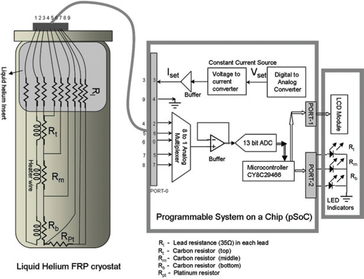
Schematic diagram of the setup with proposed instrumentation.
Whenever measurement of liquid helium level is desired, a heater current of 25 mA was passed through the heater wire wound over the carbon resistor. If the liquid helium level is higher than the carbon resistor, the higher heat transfer rate provided by the liquid helium environment restricts the rise in temperature, and hence the resistance of the carbon resistor reduces by 20 ohms compared to the resistance change (~300 ohms) when the liquid helium level in the cryostat is lower than the location of the carbon resistor. These resistance variations (~20 ohms or ~300 ohms) are indicative of the liquid helium level. During use, when the liquid helium level in the cryostat fell lower than the level of the second carbon resistor (35 cm from the bottom), it was taken as an indication for refilling the cryostat. Optimization of the heater current was carried out as part of the sensor development program undertaken earlier; these results indicated that when the heater current is passed, resistance of the sensor changes by 300 ohms when the sensor is in helium vapor (i.e., higher than the liquid level), whereas it changes by fewer than 20 ohms when the sensor is immersed in liquid helium (lower than the liquid level), indicating the possibility to use this effect for discriminating between liquid helium and helium vapor.
Circuit Realization
The embedded readout for the liquid helium level measurement system has been developed by programming the Cypress Microsystems chip CY8C29466, a 28-pin dual inline package with 16 digital and 12 analog configurable blocks, which can be configured to create any user-required functions by programming the switched capacitors of PSoC internal, in which charge movement is controlled by switching at different frequencies to realize resistors and capacitors. The m8C processor inside the PSoC controller runs at a speed as high as 12 MHz. 4 The PSoC chip is equipped with general-purpose input–output (I/O) pins that are configurable, 32 KB flash program memory, and 2 KB static random-access memory for data storage. Operating voltage varies from 4.75 V to 5.25 V.
The PSoC designer software platform has three main stages:
The device editor allows one to select and configure custom analog and digital devices using PSoC blocks.
The application editor allows one to create code using C language when PSoC blocks are initialized using library files.
The debugger allows one to test the system.
PSoC also has an in-circuit emulator that has a base unit that operates with all PSoC devices. Finally, the tested program can be loaded onto the PSoC chip using a PSoC programmer.
The chip includes analog and digital functions as user modules along with I/O ports, and it provides analog and digital communications to the outside world using an 8-bit microcontroller. The modules have been configured using the PSoC designer tool, and a PSoC programmer has been used to program the entire measurement circuit to the chip level.
For the level sensor readout, the required function blocks are (1) a constant current source to supply the known excitation current of 250 µA, (2) an analog multiplexer to multiplex the voltage leads from the four sensing resistors (PT100 and three carbon resistors) for sequential measurement of voltage across each resistor, (3) an analog-to-digital converter for digitizing the voltage signal, and (4) a liquid crystal display (LCD) to indicate the measured resistance values as well as three light-emitting diodes (LEDs) to indicate the liquid level. The constant current source has been built using a voltage-to-current converter. Using PSoC Designer, a switched capacitor block has been configured as a differential amplifier for generating a constant current 5 of 250 µA. The value of the current is determined by the reference voltage and reference resistor connected to the differential amplifier. To supply a reference voltage to the differential amplifier, a digital-to-analog converter module in PSoC blocks has been programmed to provide the desired voltage. As each carbon resistor will reach ~1200 ohms at liquid helium temperatures, the three carbon resistors and one platinum resistor connected in series constitute a total load of around 4000 ohms. Hence, a reference resistor of 4.7 K has been connected to generate a current of 250 µA from a 1.2 V reference voltage. Current was passed through the four sensing resistors (one PT100 and three carbon resistors) connected in series. To measure the resistance of each sensing resistor, it is necessary to measure voltage at each of the five points across the resistance network. A single 13-bit incremental analog-to-digital converter (ADC) has been used to measure voltage across all the four resistors using an 8-to-1 analog multiplexer, and its output is fed to a buffer to prevent loading. Buffer output is referenced to the analog ground, and the single-ended output is fed to the ADC. The ADC has been configured to measure voltage with a resolution of 0.61 mV and can measure voltages up to a maximum value of 5 V. To avoid switching transients in the analog multiplexer output, a delay of 50 µs has been introduced.
The ADC has been programmed to measure voltage with reference to ground successively at each of the five points of the resistor network, and finally the voltage drops across all the sensing resistors have been evaluated. From the known current and measured voltage drop across each sensing resistor, resistance of each of the four sensing resistors is computed and displayed on the LCD module connected to the output port of PSoC. The system has been programmed using a C compiler to indicate the helium level based on change in the resistance of each carbon resistor when the heater current is passed. Three LEDs indicate the liquid helium level in the cryostat. The entire liquid helium level measurement circuit design has been configured using PSoC Designer software, as shown in
Figure 2
. The circuit has been built, and the tested circuit has been programmed into a PSoC chip. A separate circuit has been made to energize the heater wound over the three carbon resistors. The entire unit was powered by a 9 V battery.
Figure 3
shows the embedded PSoC board developed for liquid helium level measurement.
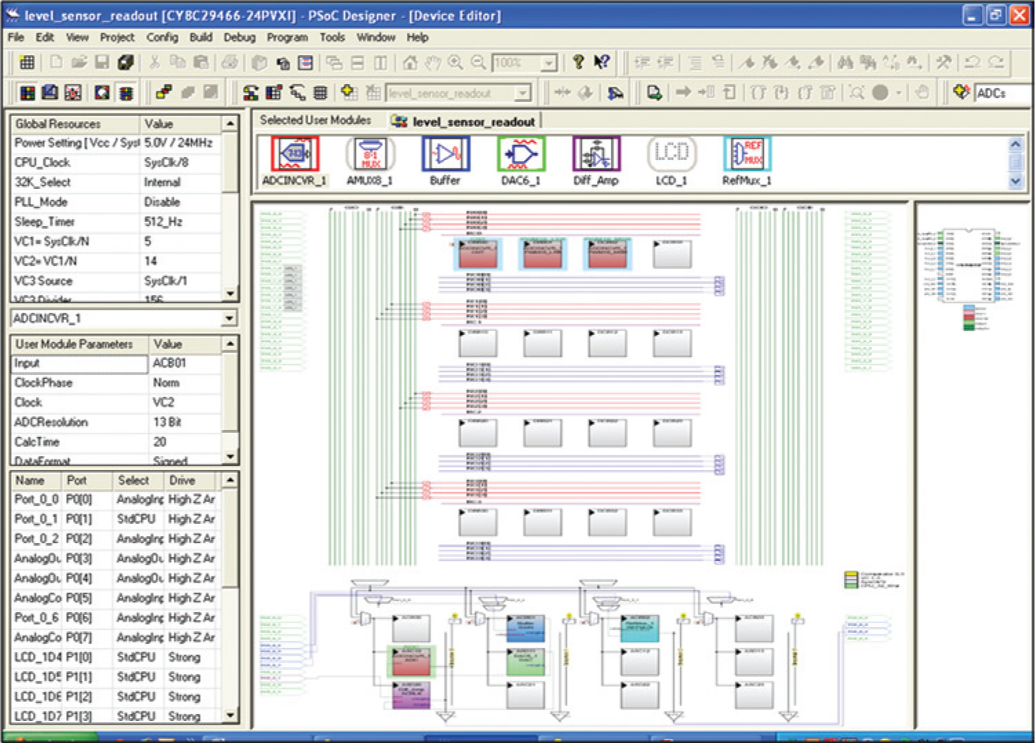
Screen shot of design implementation using PSoC Designer, version 4.4.
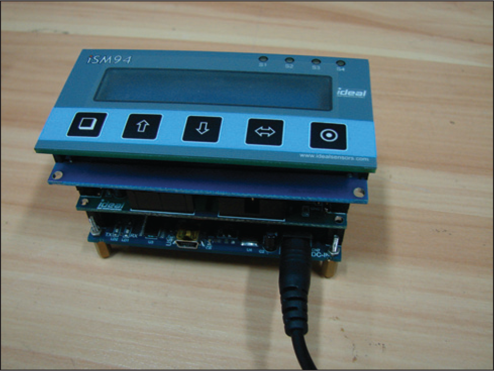
Programmable system-on-chip (PSoC) board for helium level measurements.
Results and Discussion
Before initiating the liquid helium transfer, the readout module was switched ON, and the LCD module displayed the room temperature (300 K) resistances of all the four sensing resistors: (Rpt – 110 Ω), (Rl – 115 Ω), (Rm – 115 Ω), and (Ru – 115 Ω). Once the liquid helium transfer is started and the cryostat started cooling down, the resistance PT100 steadily decreased and reached the lowest value when the temperature reached 30 K, whereas the resistance of the carbon resistors started increasing gradually and reached around 1100 Ω at 4.2 K. A resistance-versus-temperature plot for the carbon resistors and PT100 was measured separately in another experiment using a silicon diode as a temperature sensor, which is illustrated in Figure 4 . Whenever the liquid helium level is required to be monitored, the heater switch is momentarily switched ON for supplying heater current through the heater wound on the carbon resistor. When the liquid helium starts collecting (4.2 K) and the lower carbon resistor gets immersed in liquid helium, switching ON the heater current does not appreciably change the resistance of the lower carbon resistor (~20 ohms) as the heat is taken away by liquid helium, whereas the resistances of the middle (Rm) and upper carbon resistors (Ru), which were located in the helium vapor, reduced by 300 Ω, as illustrated in Figure 5 (bottom x-axis vs. y-axis). This is because helium vapor could not efficiently take away the heat produced by passage of the heater current; this increases the temperature of the middle and upper carbon resistors and consequently a decrease in their resistance. The heater current is optimally chosen in such a way that when the heater is switched ON, there is no appreciable change in the resistance of the carbon resistor if it is immersed in liquid helium, whereas there is a discernible change in resistance of the carbon resistor if it is in helium vapor. The heater current is momentarily switched ON because passing 25 mA current continuously to the heater wire will give rise to a heat load of about 20 mW to the cryostat during liquid helium transfer. The LED corresponding to a particular carbon resistor glows if the carbon resistor is immersed in liquid helium. Hence, when the liquid helium starts collecting in the cryostat, the bottom LED starts glowing first, whereas the middle and top LEDs remain OFF, indicating that the liquid helium level was lower than the locations of the middle and upper carbon resistors. When the liquid helium level reaches the middle carbon resistor, the middle LED begins to glow; and, finally, when the liquid level reaches the upper carbon resistor, the upper LED also begins to glow, indicating that the cryostat has been fully filled. The successive stages of filling are indicated as 1%, 50%, and 100%, respectively, which is illustrated in Figure 5 (top x-axis vs. y-axis). The real-time display of the resistance of each sensing resistor in the LCD module is indicative of the temperature distribution inside the cryostat. To display all four resistor values for a particular liquid helium level, the software program takes 3 s, which includes a delay of 2 s that has been deliberately introduced in the program to compensate for switch bouncing while scanning the position of the heater switch. If the measuring circuit and heater are ON, a change in the state of the sensor from being immersed in liquid helium to being in vapor (triggered, e.g., by a sudden boil-off) is expected to be detected in less than a second. It may, however, be noted that in the system reported in this manuscript, the resistance measurement is carried out using software coding in the embedded program; hence, the level sensor readout program determines the delay in the measurement of the liquid helium level (~3 s). The entire system has been automated using embedded readout with PSoC. The system performance was initially tested in a stainless-steel liquid helium dewar by wiring four carbon resistors in a dipstick before connecting the unit in the helmet-shaped MEG cryostat.
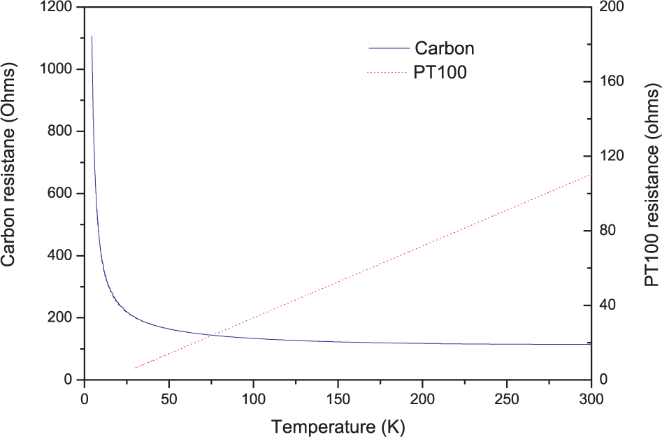
Temperature-versus-resistance plot of PT100 and a carbon resistor measured using a silicon diode thermometer.
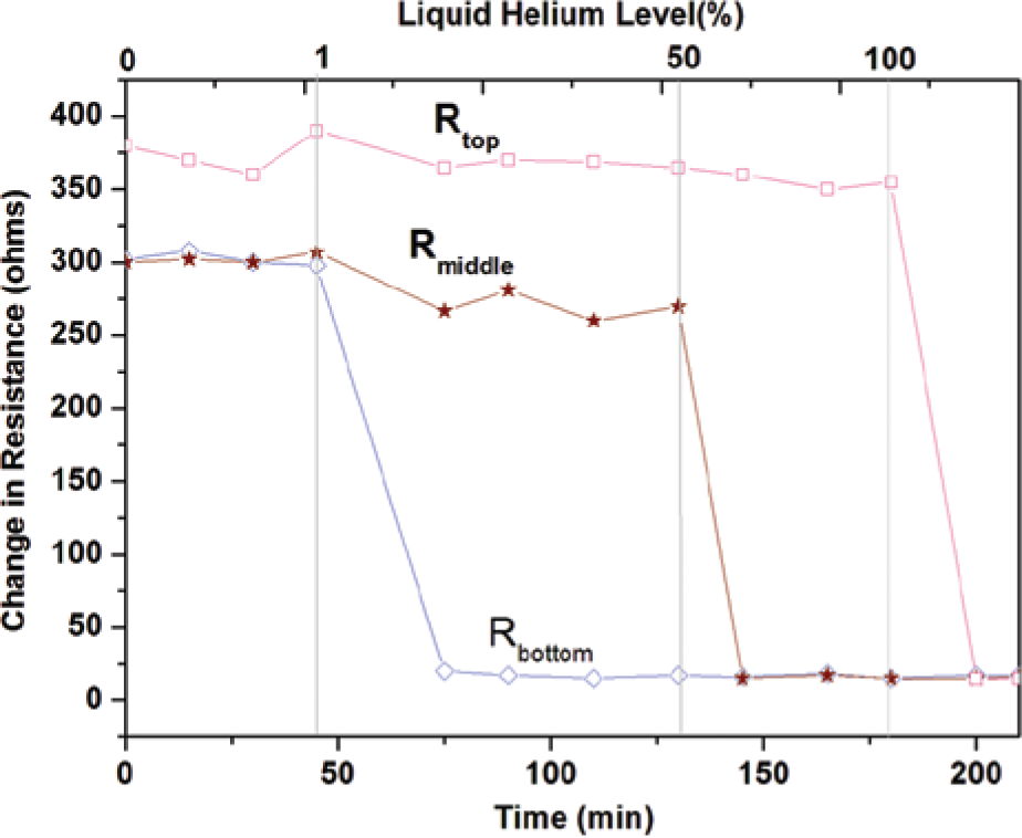
Change in resistance of three carbon resistors on localized heating during liquid helium transfer.
Conclusions
The liquid helium level sensor and PSoC-based instrumentation have been successfully developed to measure the liquid helium level at discrete intervals. The system could be continuously kept ON as the heat produced by passing 250 µA current is negligibly small. Because the cryostat is housed inside an MSR, PSoC-based readout enables the monitoring of all four sensors simultaneously, eliminating the use of multiple measuring instruments and making the system compact. The cost of the level monitoring system is greatly reduced by using carbon resistors as level sensors and building the instrumentation on a single silicon chip. This low-cost system will be useful for monitoring the liquid helium level in any liquid helium dewar or cryostat.
Footnotes
Acknowledgements
The authors would like to thank C. S. Sundar and J. Jayapandiyan for encouragement and support.
Declaration of Conflicting Interests
The authors declared no potential conflicts of interest with respect to the research, authorship, and/or publication of this article.
Funding
The authors acknowledge the support received from the Department of Atomic Energy and Department of Science & Technology, Government of India, during the execution of this work.
References
Supplementary Material
Please find the following supplemental material available below.
For Open Access articles published under a Creative Commons License, all supplemental material carries the same license as the article it is associated with.
For non-Open Access articles published, all supplemental material carries a non-exclusive license, and permission requests for re-use of supplemental material or any part of supplemental material shall be sent directly to the copyright owner as specified in the copyright notice associated with the article.