
Abstract
This article describes a commercial quartz tuning fork (QTF), 8 mm in height by 3 mm in diameter, holding a two-terminal electronic component with a nominal frequency of 32.768 kHz and 12.5 pF typical load capacitance packed in a vacuum-sealed metal container, which has been used as a sensor for low-temperature measurement with good sensitivity, repeatability, and reliability. An embedded readout design with the support of a programmable system on-chip (PSoC) and virtual instrument control program, which uses a personal computer as an input/output device, provides online data acquisition of the QTF frequency data, which will in turn provide the measurement of the low-temperature bath in which the QTF is immersed. The embedded PSoC readout captures the varying frequency signals from the QTF as a response to the measurement temperature, processes it, and sends the frequency value to a personal computer, where LabVIEW, a graphical language (“G” language), displays the data in a graphical format. The QTFs for low temperature (300 K to 77 K) are well studied, whereas a sensor using a PSoC embedded design as a readout is a novel design implementation.
Keywords
Chemically, quartz is a compound called silicon dioxide. When a crystal of quartz is properly cut and mounted, it can be made to vibrate, or oscillate, using an alternating electric current. The frequency at which the crystal oscillates is dependent on its shape and size, and the positions at which electrodes are placed on it, usually 32,768 Hz. This frequency, which is equal to 215 in binary, makes it easy to generate a 1 Hz signal by a series of two frequency dividers in readout electronics, as needed by the designer. Because of its high stability, precision, and low power consumption, the quartz crystal tuning fork has become a valuable basic component for frequency measurements. An extensive literature describes their use for a large number of other additional applications. 1
For low-temperature measurements, using silicon diodes is not more difficult, but they are typically less accurate. The reduced accuracy is a consequence of the nonlinear current voltage characteristic of diodes. Without current reversal, thermoelectric voltages and voltmeter offsets may be present, and these directly affect the achievable accuracy. The long-term accuracy and stability of the current source are also factors. The self-heating characteristic of silicon affects temperature measurements below 20 K. Apart from that, diode thermometers have the largest errors in the presence of a magnetic field and hence are not recommended for use in low-temperature measurement in the presence of a magnetic field. They are also costlier because of their hermetically shielded packages. Similarly, Cernox, a resistance thermometer, also depends on long-term accuracy and stability of the current source. The self-heating effect of the Cernox thermometer affects temperature measurements below 10 K. Quartz tuning forks (QTFs) are much cheaper and more easily available components, and the compact package of QTFs permits immersion in a low-temperature medium. QTFs claim several advantages compared with other costlier low-temperature sensors. The major advantage of QTFs is that they do not require excitation current; hence, self-heating will not occur, and they are also insensitive to magnetic fields.
Commercial QTFs, shown in Figure 1, typically measure less than 8 mm in height by 3 mm in diameter, holding a two-terminal electronic component, and they are vacuum sealed in a metal canister. These forks are designed to provide reliable timing devices through a calibrated resonance frequency, usually near 32.768 kHz. 2 To drive oscillations, an alternating voltage is applied across two electrodes plated on the prongs of the fork; the piezoelectric effect converts these mechanical oscillations into electrical current, which can be easily measured. However, the QTF offers other important advantages as a sensor of its cryogenic environment because they are highly sensitive indicators of the physical properties of the medium in which they are immersed. A major advantage in many applications is that to drive these piezoelectric devices, no magnetic fields are needed, and in fact, they are highly insensitive to them.3,4 Because quartz is diamagnetic with a magnetic permeability less than a relative permeability, diamagnetic substances have zero net magnetic moment because they have the same number of electrons of opposing spin; hence, quartz is insensitive to magnetic fields.
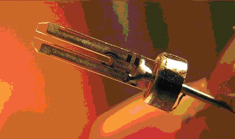
A commercial quartz tuning fork (QTF).
This article describes the embedded design implementation with the expectation that industrially produced quartz oscillators, with a calibrated standard frequency of 32 768 Hz at room temperature, would be reasonably identical and could be used as secondary thermometers without need for recalibration.
QTF as a Low-Temperature Sensor
QTFs are potential candidates in low-temperature measurements because of their high stability and insensitiveness to magnetic fields coupled with their ability to resist corrosion. An extensive literature5–7 describes the behavior of quartz crystal oscillators at very low temperatures. This temperature sensitivity of the resonator, the independence of its resonance frequency from the presence of a magnetic field, and the high-frequency output signal convenient for digital treatment of the information show that the thermosensitive quartz resonator possesses considerable potential for application as a quartz thermosensor for cryogenic temperatures as well. Various other studies have established a relationship between the oscillation frequency of the quartz fork and its surrounding temperature.8,9
This article describes implementation of three major modules: excitation of the QTF, measurement of signal frequency using an embedded programmable system on-chip (PSoC), and the processing of the measured frequency using LabVIEW, a graphical language, residing in a personal computer (PC).
The embedded system refers to the required circuitry for any system design such as analog, digital, and digital communication blocks programmed in a single integrated chip. Innovative programmable embedded hardware such as field programmable gate array, application-specific integrated circuit, PSoC, digital signal processor, and several new microcontrollers are examples of the embedded design solution. The main advantage in embedded design is that before the target hardware becomes available, developers can use a software-processor simulator running on the host or a general purpose evaluation board in place of the target prototype. PSoC 10 is a mixed-signal array of systems on-chips that integrate a microcontroller and analog and digital components that typically surround it in an embedded system. LabVIEW (Laboratory Virtual Instrumentation Engineering Workbench) is a platform and development environment for a visual programming graphical language (“G” language) that uses the data-flow technique. Many libraries with a large number of functions for data acquisition, signal generation, mathematics, statistics, signal conditioning, analysis, and so forth, along with numerous graphical interface elements, are provided in several LabVIEW package options.
Excitation of the QTF
In principle, the tuning fork can be either electrically excited through the tuning fork electrodes (self-driving mode) or mechanically driven by an additional piezoelectric element (externally driving mode). The self-driving mode circuit shown in Figure 2. Figure 1 has been called out in second para first line of this page used to excite the tuning fork is a typical complementary metal oxide semiconductor (CMOS; technology for IC design) oscillator circuit, which uses 74HCT04 IC, a hex inverter.
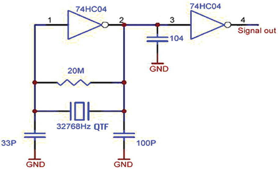
Quartz tuning fork excitation oscillator circuit.
Figure 3 shows the block diagram of the design and its implementation. The QTF sensor is connected to the readout electronics designed with PSoC via the self-excitation CMOS front-end circuit. The single PSoC chip is programmed in such a way to accept the TTL pulses of 0 to 5 V from the excitation circuit and does pulse counting with the high-precision counter timer programmed within it. The count data per second as a frequency from the counter timer module has been transferred internally to the serial communication building block universal asynchronous receive transmit (UART), through which the frequency data reach the PC via its serial port. The control program written in LabVIEW acquires the frequency data of the QTF through the embedded PSoC design and saves it in a user-specified file path as well as in an online display of frequency data and online plotting of data in a waveform graph.
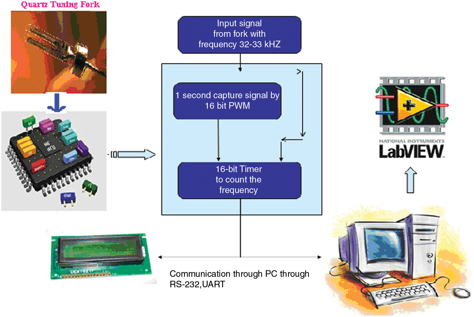
Block diagram of the tuning fork sensor and programmable system on-chip embedded design implementation.
Measurement of QTF Signal Frequency Using PSoC
PSoC is a family of mixed-signal arrays made by Cypress Semiconductor, featuring a microcontroller and configurable integrated analog and digital peripherals. PSoC is a software-configured, mixed-signal array with a built-in microcontroller unit (MCU) core, an m8C microcontroller unit. PSoC most closely resembles a microcontroller in usage, where code is executed to interact with the user-specified peripheral functions called “user modules.” Global resource settings in PSoC Designer enable the designer to configure system-level registers through an easy-to-use graphical user interface (GUI). The PSoC Designer integrated development environment generates the start-up configuration code and peripherals automatically based on the user’s selections in a visual studio–like GUI. The visual design is compiled to executable code without exposing the user to the underlying converted code, although a visual design can be converted and used as a basis of a traditional code-based design in PSoC Designer.
In this design, the signal from the excitation circuit is fed to the PSoC interface design. PSoC Designer uses all eight digital blocks for a counter to count the QTF frequency data as well as for the clock divider for the serial communication block, the timer for acquiring the frequency information, and the serial communication block UART for interfacing with the PC’s serial port, as shown in Figure 4 . Table 1 lists the various user modules that have been used in this design.
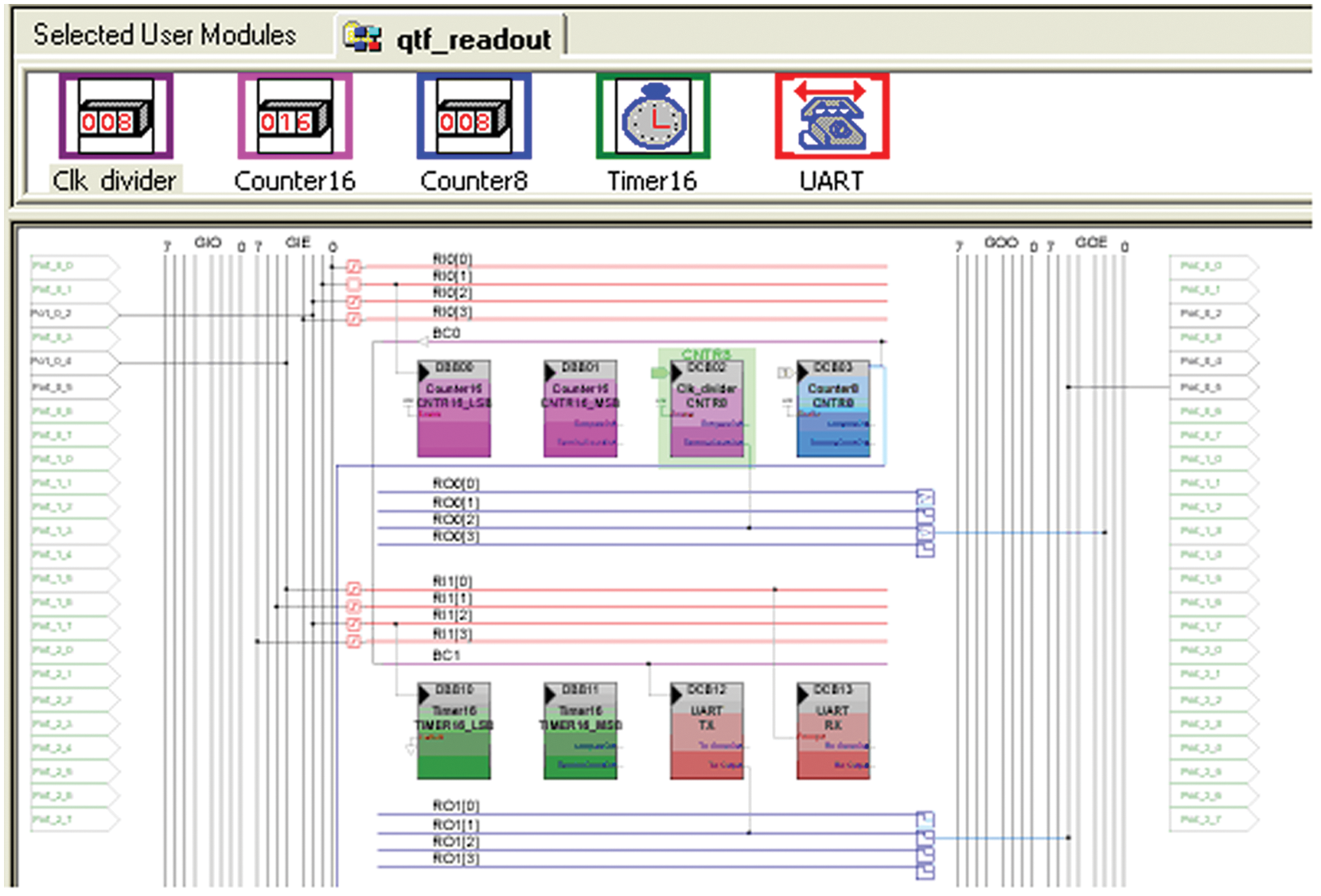
PSoC Designer for tuning fork readout.
Programmable System On-Chip Built-in User Modules in This Design
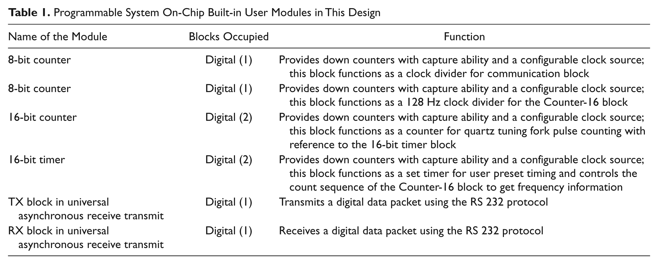
Figure 5 shows the pin configuration of the CY8C27443 28-pin PSoC device. A 16-bit timer module placed in two digital blocks (DBB10 for LSB and DBB11 for MSB) allows the user to set the required preset time. In this design, set timing is 1 s to get the frequency change. The option for a wide dynamic range preset time from milliseconds to several minutes can be achieved by exploiting the use of the timer interrupt routine. 11 Similarly, a 16-bit counter module is placed in another two digital blocks (DBB00 for LSB DBB01 for MSB), as counting of tuning fork frequency has been implemented to count up to 65 535 (64 K) counts. Counter interrupt can also be enabled to have several million counts using its interrupt service routine. The remaining two digital blocks are used for serial communication with the PC through the UART. The transmit block (TX) is placed in DCB12, and the receive block (RX) is placed in DCB13 for serial communication. In this application, the UART baud rate is set to 115 200. The processor clock is divided by an eight-bit counter (placed in DCB03) to generate a clock for the serial communication UART. The clock divider user module, which occupies one digital block (DCB02), is another eight-bit counter used for basic clock generation. Dividing the CPU 32 KHz clock by 250 provides a 128 Hz clock for the Timer16 user module, which occupies two digital blocks (DBB10 LSB and DBB11 MSB).
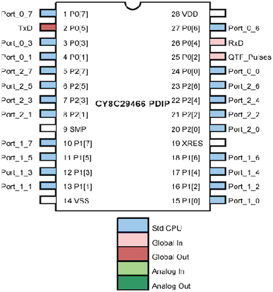
PSoC Device pin out.
The counted value from the Counter-16 block activated by the Timer-16 block for the preset time of 1 s provides the frequency of the tuning fork and is fed to a PC through the UART communication block of the PSoC device, which can use protocols such as the RS-232 serial communication protocol or USB protocol. A serial communication baud rate of 115 200 bits per second (bps) has been used in this design. The PSoC integrated source code editor written with C complier shown in the appendix is a self-explanatory control program residing within the PSoC chip, which interacts with the above-listed user modules built in PSoC for the total functionality of the QTF embedded readout design. PSoC is a software-configured, mixed-signal array with a built-in MCU core, which bridges the integrated source code written in C and the user-specified peripheral functions called “user modules.”
GUI Control Program in LabVIEW
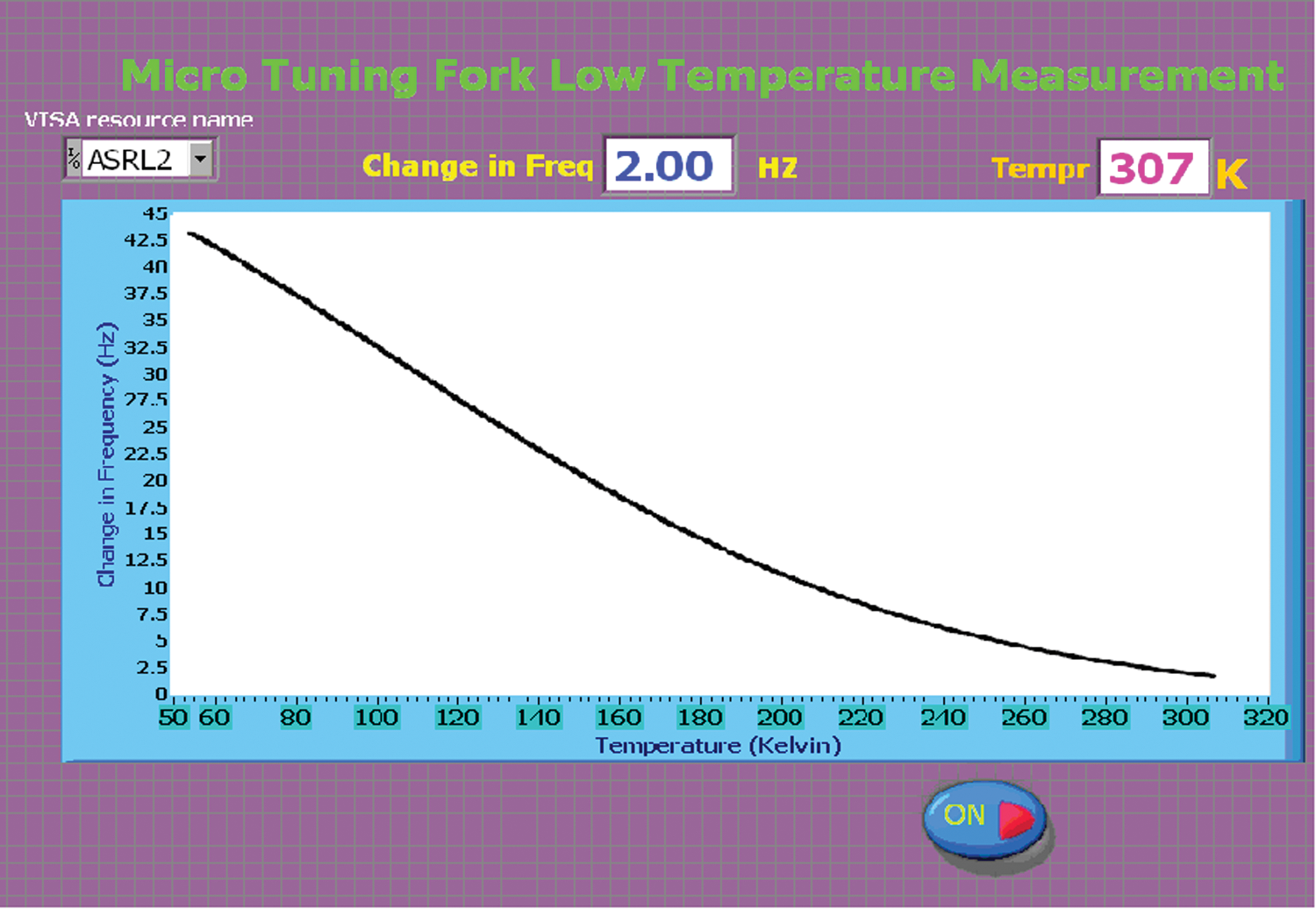
The QTF frequency values read by the PSoC interface board are fed to a PC through its serial port. The LabVIEW control program developed within the PC offers a GUI based on the concept of virtual instruments (VIs) programming. VIs are an application of general purpose digital PCs for the measurement and control of various parameters such as temperature, flow, pressure, position, and so forth. VI programs mimic the control processes, which are in a remote area, on the PC screen. The VI program allows the user to set counter and timer values, start the counter and timer modules, and acquire the QTF frequency data in the PC memory. The counted values are displayed on the LabVIEW front panel as frequency data. In the menu-driven VI program, online acquiring data, plotting, saving data, and load data options are also provided. The block diagram of this virtual instrument program (VI) is shown in Figure 6 , and Figure 7 shows its functional block diagram. The frequency of the tuning fork is indicative of the temperature of the medium (liquid nitrogen). The temperature of liquid nitrogen can thus be determined from the frequency obtained from the PSoC interface design.
Front panel diagram of the virtual instrument program for tuning fork readout design.

Functional diagram of the virtual instrument control program for tuning fork readout design.
The PSoC design acquires the frequency data of the tuning fork corresponding to the temperature of the bath and transfers them to the PC through its serial port by the VI control program residing within the PC, with the transfer speed of 115 k baud rate (i.e., number of bits per second). Figure 6 shows the front panel diagram of the VI control program.
Testing the QTF with the Embedded Design and VI Program
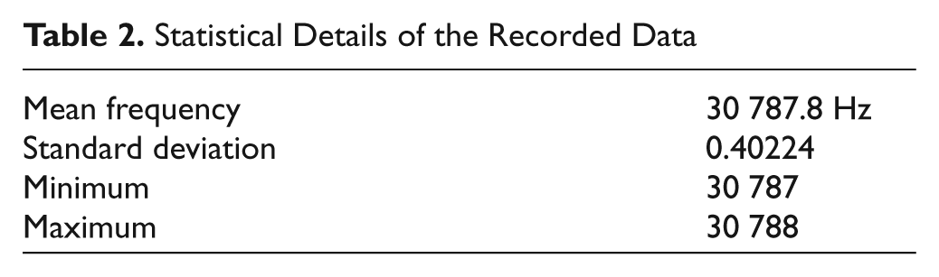
This PSoC embedded design has been successfully tested in liquid nitrogen, which boils at a temperature of 77.8 K at 1 atm. The QTF registered an oscillation frequency of 30 808 Hz at the laboratory temperature of 300 K. On dipping the fork into liquid nitrogen, the frequency of oscillation of the fork dropped to about 30 788 Hz. A response time of about 10 s was observed for this frequency shift of −20 Hz. The sensor took about 32 s to recover from 77.8 K to the ambient temperature of 300 K. The frequency readings were noted down for a duration of 100 s. The graph hence plotted is shown below ( Fig. 8 ). The graph indicates the consistency in the frequency measurement.
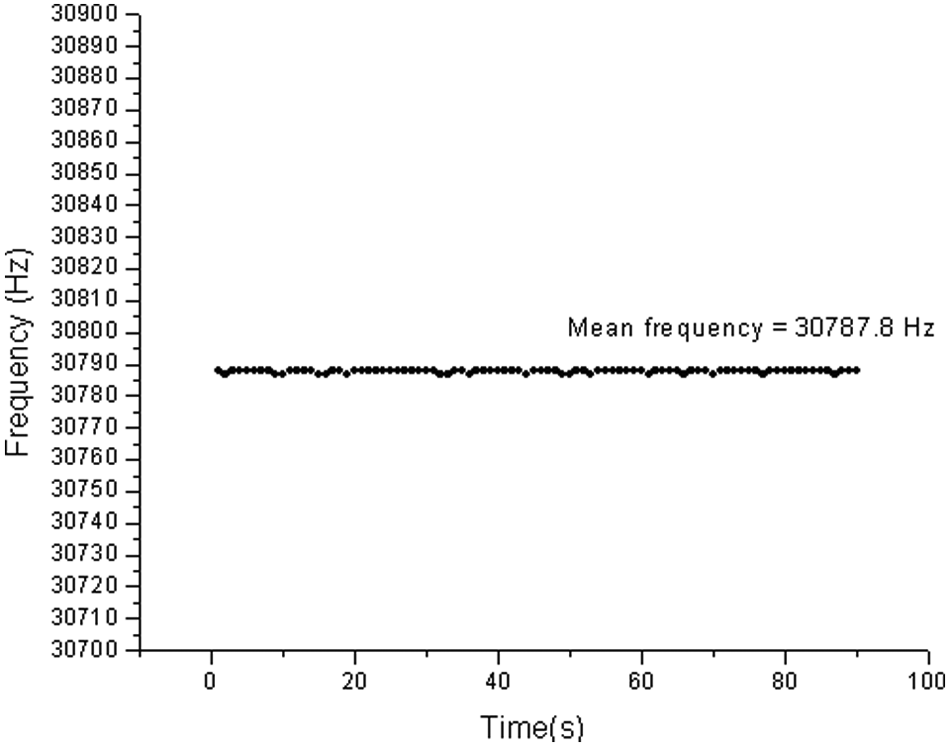
Stability in measurement of oscillation frequency for 100 s at 77.80 K.
Table 2 provides the statistical tendencies of the data obtained.
Statistical Details of the Recorded Data
A low-temperature measurement setup is shown in Figure 9 , and a dipstick length of approximately 3 m as displayed was used for inserting the forks into the Dewar. First, a pair of lengthy Teflon wires was inserted into the metal dipstick. The metal leads from the tuning fork were soldered with the Teflon wire to one end of the dipstick, which touches the liquid nitrogen inside. To minimize the leakage of liquid nitrogen, the other end of the dipstick was sealed with araldite and was kept for drying for 24 h. In addition, a pair of wires was coiled to the dipstick and grounded to minimize the stray capacitances. A heater was placed in the chamber, which raises the temperature from 77 K to 300 K. The dipstick was slowly lowered into a liquid nitrogen Dewar until the stick cooled and liquid nitrogen was able to enter though the capillary. Before letting the inner chamber fill with liquid, the vacuum jacket was evacuated to maintain lower temperatures in the inner chamber. Already calibrated Cernox (zirconium oxy-nitride) thin-film resistance temperature sensors have been attached near the tuning fork for the temperature measurement and calibration of QTF as a secondary thermometer.
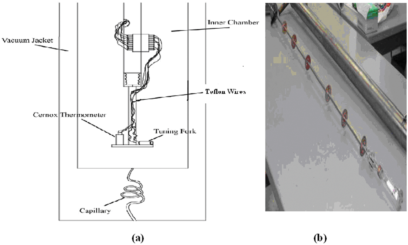
(a) Setup for low-temperature measurement. (b) Dipstick for carrying the forks into the Dewar.
Conclusion
A novel application with an indigenous electronic design was explored using a cost-effective commercial QTF and embedded design with PSoC. The tuning fork with a nominal frequency of 32.768 kHz and a 12.5 pF typical load capacitance packed in a vacuum-sealed metal container was used. Our experiments indicate that QTFs show a shift in frequency that is steady and repeatable. The oscillation frequencies of quartz forks are also very sensitive to minute changes in temperature. The work presented here was supported by data obtained at the boiling temperature of liquid nitrogen. On a temperature transition from 300 K to 77.8 K, the fork registered a drop in frequency of 20 Hz, with the response time being 10 s. The time for recovery from 77.8 K to 300 K was approximately 32 s. The results were thus consistent at liquid nitrogen temperature. The experiments can be carried out at even lower temperatures, such as that of liquid helium. In conclusion, the present QTF sensor can be used for low-temperature measurement applications. The frequency shift at low temperatures is very consistent with changes in temperature, and hence, QTFs with an embedded design implementation using PSoC can provide a stable and cost-effective solution as a low-temperature measurement device. The use of phase-locked-loop (PLL) design implementation within the same PSoC chip with a higher sampling rate can detect the change in frequency of the QTF below liquid nitrogen temperature with a very high resolution. PLL is a control system that generates an output signal whose phase is related to the phase of an input “reference” signal. PLL is a lock-in detection technique used for the recovery of small changes in signals that otherwise would be lost in noise. In this design, by means of implementing the PLL technique, a very small change in frequency due to change in temperature can be detected, and the design provides higher resolution in measurement.
Footnotes
Appendix A: C Source
/* The main C program for the PSoC Design for Quartz Tuning Fork (QTF) Read-out. This application design provides pulse counts per sec i.e., Frequency. */
#include <m8c.h>
#include "PSoCAPI.h"
#include "stdlib.h"
#include "uart.h"
#include "Timer16.h"
#include "Clk_divider.h"
#define CR 0x0D
#define LF 0x0A
#define HEXBASE 16
char cIndex;
long int Countdata, Countvalue;
char Count[4];
char tmrw[4];
char tmrh[4];
BYTE bData;
unsigned int value;
void Set_timer(void);
void Ascii2Hex(void);
void Counter_read(void);
void DoTask(void);
void Initialize (void)
{
UART_IntCntl(UART_ENABLE_RX_INT);
Counter8_WritePeriod(26); // 26 Sets up baud rate generator
Counter8_WriteCompareValue(13); // 13 Turns on baud rate generator
Counter8_EnableInt();
Counter8_Start();
UART_Start(UART_PARITY_NONE);
RefGND_Start(RefGND_HIGHPOWER); // Turn on power to the CT block
RefGND_RefSelect(RefGND_AGND); // Apply AGND to ABUS2.
Clk_divider_WritePeriod(0xFA); /* Clk_divider divides the 32kHz clock by 250
* and provides 128 Hz clock to Timer16. */
Clk_divider_WriteCompareValue(0x7D);
Clk_divider_EnableInt(); // Ensures the interrupt is enabled
Timer16_WriteCompareValue(00001);
Count[0] = 0;
Counter16_WritePeriod(0xFFFF); // Reloads Counter16 when it overflows
M8C_EnableGInt; // Turn on interrupts
}
signed char ExtractHex(unsigned char Val)
{
if(Val < '0') // If the value is invalid return error
return −1;
else if(Val <= '9') // If the value is between ASCII 0 and 9
{ Val -= '0'; // then return binary 0-9
return Val;
}
Val & = 0xdf;
if (Val < 'A') // Return an error if the value is
return −1; // between ASCII 9 and A
else if (Val < 'G') // If the value is between ASCII A and F
{ Val -= 'A'; // then return binary 10 - 15
Val += 10;
return Val;
}
}
void Counter_read(void)
{
Countdata=Counter16_wReadCounter();
Countdata &=0xFFFFF;
Countvalue = ~ Countdata;
itoa( Count, Countvalue, HEXBASE);
cIndex = 0;
/* Sends the value of Count to the serial port */
while (Count[ cIndex])
{
while (!(bUART_ReadTxStatus() &
UART_TX_BUFFER_EMPTY) ) {}
UART_SendData( Count[ cIndex]);
cIndex++;
}
if ( Count[0] != 0)
{
while (!(bUART_ReadTxStatus() & UART_TX_BUFFER_EMPTY)) {}
UART_SendData( LF);
while (!(bUART_ReadTxStatus() & UART_TX_BUFFER_EMPTY)) {}
UART_SendData( CR);
Count[0] = 0;
cIndex = 0;
}
}
void Set_Timer(void)
{
int i;
unsigned int val1, val2, val3, val4;
i = 0;
UART_CPutString("Set Time in Sec:");
UART_IntCntl(UART_DISABLE_RX_INT);
while(i < 4)
{
tmrw[i]= UART_cGetChar();
tmrh[i]= ExtractHex(tmrw[i]);
i++;
}
val1 = tmrh[0]<<12;
val2 = tmrh[1]<<8;
val3 = tmrh[2]<<4;
val4 = tmrh[3];
value = val1|=val2|=val3|=val4;
UART_PutSHexInt(value);
Timer16_WritePeriod(value);
Counter16_WritePeriod(0xFFFF);
}
void main()
{
BYTE bData;
unsigned int value;
UART_CmdReset();
Initialize();
while (1)
{
bData = UART_bReadRxData();
bData &= 0xdf;
if ((bData >= 'G'))
{ switch (bData)
{
case 'T' : Set_Timer();
UART_CPutString("\r\nTime Set OK\r\n");
break;
case 'R' : Counter16_Stop(); // Stop Counter16, Timer16, Clk_divider
Timer16_Stop();
Clk_divider_Stop();
break;
case 'S' : Clk_divider_Start(); // Start Counter_Timer
Timer16_Start();
Counter16_Start();
break;
default : UART_CPutString("\r\nWelcome to PSoC_Quartz Tuning Fork Read-out V1.1\r\n");
break;
}
UART_CmdReset();
}
}
}
The authors declared no potential conflicts of interest with respect to the research, authorship, and/or publication of this article.
The authors received no financial support for the research, authorship, and/or publication of this article.