
Abstract
Microscale systems that enable measurements of oncological phenomena at the single-cell level have a great capacity to improve therapeutic strategies and diagnostics. Such measurements can reveal unprecedented insights into cellular heterogeneity and its implications into the progression and treatment of complicated cellular disease processes such as those found in cancer. We describe a novel fluid-delivery platform to interface with low-cost microfluidic chips containing arrays of microchambers. Using multiple pairs of needles to aspirate and dispense reagents, the platform enables automated coating of chambers, loading of cells, and treatment with growth media or other agents (e.g., drugs, fixatives, membrane permeabilizers, washes, stains, etc.). The chips can be quantitatively assayed using standard fluorescence-based immunocytochemistry, microscopy, and image analysis tools, to determine, for example, drug response based on differences in protein expression and/or activation of cellular targets on an individual-cell level. In general, automation of fluid and cell handling increases repeatability, eliminates human error, and enables increased throughput, especially for sophisticated, multistep assays such as multiparameter quantitative immunocytochemistry. We report the design of the automated platform and compare several aspects of its performance to manually-loaded microfluidic chips.
Keywords
Introduction
Microfluidic-based platforms are increasingly being found to be valuable, transformative tools for cell-based assaying, and are poised to have a substantial impact in the medical and life sciences.1,2 By providing unprecedented control of the microenvironment and the ability to manipulate tiny sample and reagent volumes, microfluidics enables comparisons of responses of relatively small numbers of cells to different conditions, even down to the level of individual cells.3,4
Microfluidic platforms for immunoassays, in particular, can advance cancer drug discovery and development by monitoring dynamic changes in drug effect and confirming how cytotoxicity corresponds to affect specific molecular targets.5–9 For clinical diagnostic applications, these platforms are beginning to meet the requirements for personalized medicine by enabling measurements of patients’ individual tumor cells. By capturing minute molecular differences from cell to cell and patient to patient, malignancy and choice of most effective therapy can be determined. 10 In previous work, we demonstrated the use of poly(dimethylsiloxane) (PDMS) microfluidic devices for simultaneous measurement of expression of four critical signaling proteins to study cellular heterogeneity in cancer cell lines and clinical samples. Such measurements revealed significant heterogeneity within and between tumors and have many potential applications to improve clinical care. 10
For these microfluidic platforms to find routine use by personnel in biology or clinical pathology laboratories, they require significant improvements in automation and, in some cases, throughput and multiplexing. Several approaches for automating cell loading and capture, reagent loading, and performing washing steps in repetitive analytical protocols have been reported.11–13 These systems range widely in their style of chip interfaces (e.g., fixed tubing connections or flexible connections via the use of moveable pipette tips), as well as mode of liquid delivery (e.g., peristaltic pumping, gravity-driven flow, capillary action, pressure-driven flow, or passive pumping). Many of these approaches, described in more detail below, use a microwell plate format to enable existing laboratory robotics to dispense reagents in a high-throughput and flexible manner and to eliminate the dead volumes and specialized connections encountered when connecting microfluidic chips directly to external fluid reservoirs. 14
Controlling flow rate is an important consideration when doing cellular immunoassays in microfluidic devices to ensure that shear forces on cells are well controlled. 10 Yu et al. 14 reported the use of on-chip microvalves and peristaltic pumps to circulate cell culture medium from a fixed tubing connection or from on-chip reservoirs (into which liquids can be pipetted). To provide increased flexibility in the number of different liquids delivered to the cells, on-chip microvalves can be used for fluid selection. In the system reported by Rohde et al. 15 for studying Caenorhabditis elegans, liquids are drawn into the chip from a microwell plate situated underneath the chip, and microvalves are employed to control which fluid is delivered to the analysis chamber. 15 Although these approaches provide excellent control of flow and selection among several fluid sources, the microfluidic chip fabrication process to form the active fluid control elements is complex, involving at least two layers that must be aligned with high precision and bonding. Furthermore, these active elements require numerous connections to the chip to provide actuation pressures.
Fluid flows can also be driven by pressure. Conant et al. 16 described a microfluidic device in a 48-well plate format, consisting of 24 microchannels, each situated between a pair of wells. By applying pressure to the wells via a special pneumatic interface, fluid can be flowed through the intervening channels at well-defined flow rates to study dynamic biophysical cell properties associated with shear stress. 16 Choi et al. 17 reported a microfluidic device in a 96-well plate format that is similar, but that has 11 wells connected to each of eight common ports via channels. Applying pressure or vacuum at the common port can move fluids through the 11 channels to perform assays (e.g., parallel binding assays). 17 Although these pneumatic approaches use a simpler chip design than the multilayer PDMS chips described above, and although they provide considerable flexibility in reagent introduction by providing microwells that can be accessed by pipetting or robotics, the need for attachment of a pneumatic interface is cumbersome.
Other methods, such as the GRAVI platform, rely on gravity and capillary forces to drive liquid dispensed in the microwells through intervening microchannels to perform immunoassays. 18 No connections are needed to the dispensing platform to control the fluid flow. Gravity-driven flow is also used on the commercially-available Pearl Microfluidic plate (CellASIC, Inc., Hayward, CA) that consists of 32 independent microfluidic culture units in a 96-well plate format to study long-term cellular function. 19 Despite their simplicity, flow rate may be difficult to control, especially if different types of reagents are needed, because flow will depend on the geometry and materials of the channels as well as properties (density, viscosity, etc.) of the liquids.
Meyvantsson et al. 20 reported another passive pumping approach in which flow is achieved in microfluidic channels through surface tension differences from liquid droplets deposited on the inlet and outlet ports. Puccinelli et al. 21 showed impressive robustness and uniformity in cell staining when performing standard biological assays. Inertia-enhanced passive pumping, pioneered by Resto et al., 22 can increase fluid flow within the microchambers by leveraging the inertia in microdroplets ejected from nozzles. However, controlling precise flow rates within a microchamber using passive pumping is difficult as the flow rate is a function of the change in volume over the change in time. 21
Here we describe a unique automated platform that performs flexible sequences of solution loading via automated pipetting and incubation steps for individually addressable cell chambers in an array-format microfluidic chip that overcomes all of the above limitations. Rather than rely on other pumping mechanisms, we use the pipetting system itself to drive fluid flow. We developed a needle-based fluid delivery system to inject precise volumes of reagents into microchambers at a set flow rate. The system has very low dead volume due to the absence of tubing and long microchannels. Pairs of needles simultaneously interface with a given cell chamber, enabling simultaneous dispensing of new liquid (stored in one of the needles) and collection of original, waste liquid (into a companion needle), driven by external syringe pumps. The microfluidic chips are sealed by a low-permeability material to prevent evaporation during long incubation steps and thus reduce or eliminate the need for replenishing liquids. The overall platform is capable of performing automated protocols for disaggregated cell specimen handling, as well as cell profiling and other assays. 10
Materials and Methods
Fluid-Dispensing Platform and Control System
In this work, an automated pipetting system was developed to automatically introduce liquids containing cells, reagents, and wash solutions in particular sequences to microfluidic chips containing arrays of chambers (eight rows of three per chip). The fluid-handling system is based on a modified Nanodrop NS-2 (Innovadyne, Rohnert Park, CA), a high-accuracy pipetting robot that accommodates two microwell plates. In one plate nest position, a custom chip holder was placed to provide repeatable mounting of up to three disposable microfluidic chips in the system ( Fig. 1b ). The chip holder has the dimensions of a microwell plate and was designed to be compatible with other plate-handling and -processing tools. A conventional 96-well plate is loaded into the second plate nest as the source of cells and reagents ( Fig. 1c ). The system also has a tip-washing station and secondary reagent station that can hold up to four troughs for media, wash buffers, or other frequently needed liquids. Three independent dual-syringe pumps (MicroLab 900; Hamilton Company, Reno, NV) are used for coordinated liquid handling at the inlets and outlets of the microfluidic cell chambers for simultaneous dispensing of a new liquid to the inlet and aspiration of the previous liquid from the outlet at programmable flow rates (1.67–50 µL/s). Each syringe is connected via tubing to a custom-designed needle tip for interfacing to the microfluidic chip ( Fig. 1d ). The inlet port of each syringe pump valve is connected to the pressurized deionized water reservoir of the Nanodrop system, and the bypass port is connected to the Nanodrop fluidic system for cleaning and priming.
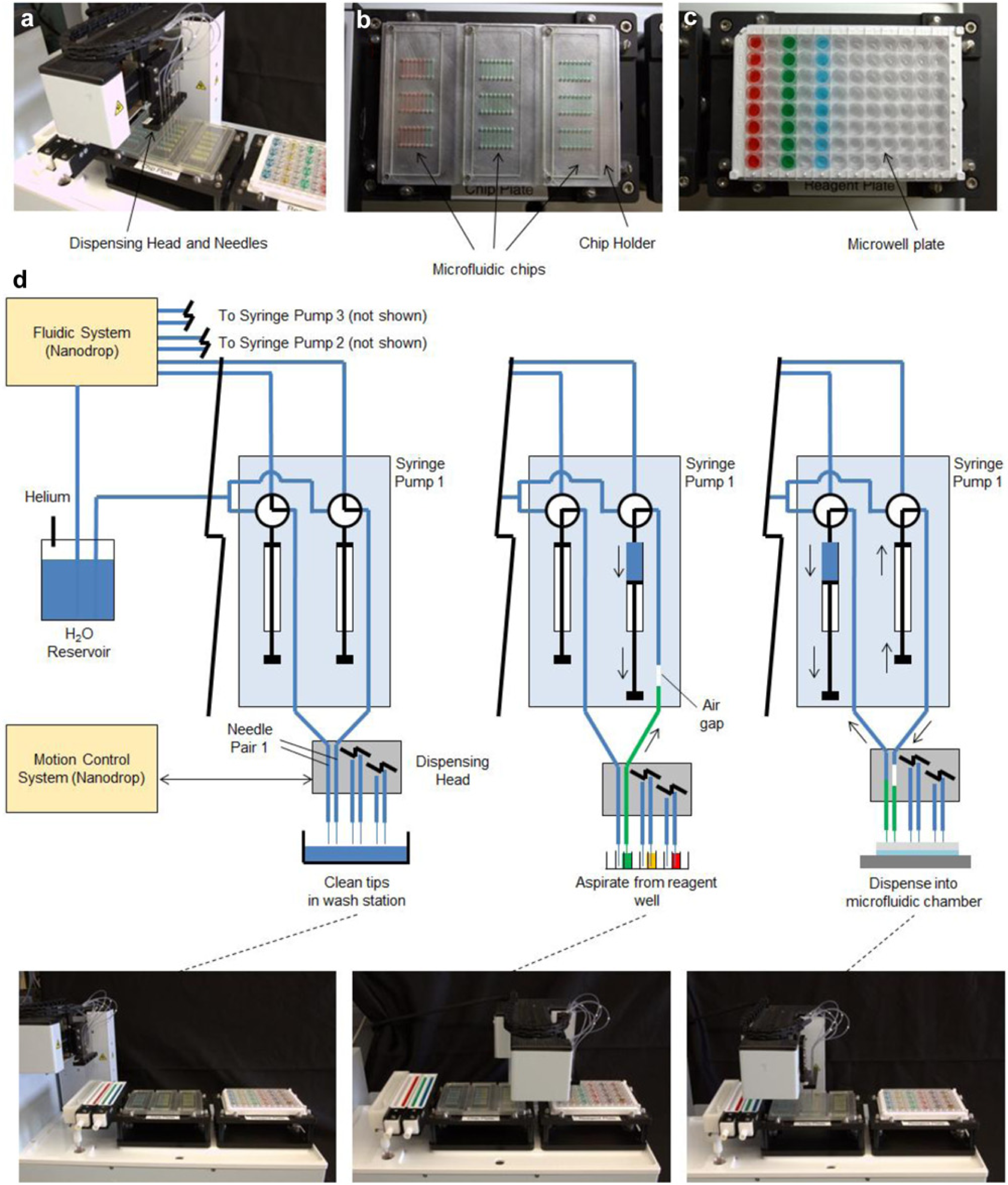
Automated microfluidic cell-based assay platform. (
The three pairs of tips for aspirating and dispensing liquids are fixed on a head driven by a three-axis robotic stage. The x-y motion allows the tips to be positioned above the wash station or above any of the eight columns of any of the three microfluidic chips or above any corresponding column of reagent wells in the reagent plate. The z-motion allows the tip to be raised to a clearance position (while moving) and lowered to the appropriate depth into reagent wells or chips for aspirating or dispensing reagents or into the cleaning station for cleaning the tips. In practice, the y-axis motion was not needed. The system configuration while performing various operations (washing, aspirating, and dispensing) is illustrated in Figure 1d .
Software for the system is programmed in NanoBuilder (Innovadyne). Special function calls are used within NanoBuilder to activate the external syringe pumps. The software allows the user to create and select “recipes” to perform all assaying functions for a set of microfluidic chambers (in up to three chips). Each recipe consists of a number of sequential liquid-delivery steps of aspirating from a designated reagent location (the volume is computed from the number of desired chambers to fill), moving the tips and dispensing to the chip, then thoroughly cleaning the tips and waiting a predetermined amount of time for incubation until the next operation is performed. An example recipe for performing immunocytochemistry is provided in
Microfluidic Chip Design and Fabrication
The microfluidic chip ( Fig. 2 ) consists of four layers: (1) a glass microscope slide substrate (L 75 mm × W 25 mm, 1.00 mm thick); (2) a double-sided adhesive-backed polyethylene terephthalate (PET) tape (0.15 mm thick), laser-patterned with an array of cutouts that form the array of microchambers in the final chip; (3) a rigid acrylic alignment plate (2.33 mm thick) with computer numerical control drilled inlet and outlet holes (a pair of 1.0 mm diameter holes for each microchamber) and drilled holes to mate with alignment pegs in the specially designed chip holder; and (4) an adhesive-backed polyurethane evaporation barrier (3M 8673; 3M Films, Greenville, SC) (L 75 mm × W 25 mm × 0.36 mm thick) adhered to the acrylic such that it covers all inlets and outlets. The channel layer tape (ALine, Inc., Rancho Dominguez, CA) was prepared by laminating 500 µm silicone-based pressure-sensitive adhesive on both sides of a sheet of polyethylene PET film (500 µm thick; Dupont Teijin Films, Carrollton, TX). The 3 × 8 array of cutouts defines 24 microchambers (L 9.00 mm, W 1.00mm). The volume of each chamber, including the inlet and outlet port, is 5.0 µL.
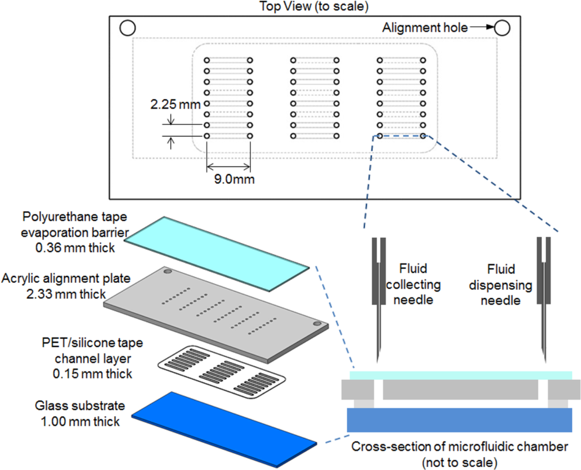
Schematic of individual microfluidic cell assay chip.
A new polyurethane tape layer is placed onto the chip prior to filling. The polyurethane evaporation layer prevents fluid from evaporating from the inlets and outlets of the chambers and prevents air from entering the chambers. During the aspirating/dispensing steps, the needle tips of the fluid delivery robot puncture the tape and exchange fluid from each chamber. After completion of an assay (i.e., timed drug treatment, immunolabeling, incubation, and washing), the punctured tape is carefully peeled off manually along the length of the chamber and replaced with a new tape layer and is stored until imaging. Although there may be minute amounts of liquid residue on the adhesive side of the tape, no cross-contamination occurs.
Microfluidic Chip Holder
The microfluidic chip holder ( Fig. 1b ) is fabricated from a solid piece of aluminum and is designed to fit into a standard plate nest. Holes are drilled into the aluminum plate, and dowel pins (3.2 mm diameter) are press fit into the plate to serve as chip alignment pins. Each chip has two holes in the rigid acrylic layer (the same layer in which inlet and outlet holes are located) that mate to these pins for precise positioning. Up to three chips can be installed in the holder, enabling a total of 72 individually addressable chambers to be accessed by the robot at a given time.
Fluidic Injection Needles
To interface with the chip, custom-fabricated rigid stainless-steel needle tips (Ziggy’s Tubes and Wires, Pleasant Hill, TN) were used. Each of these tips consisted of a fine needle (#30, ID 0.14 mm, OD 0.31 mm, 11.3° bevel) press fit into a larger stainless-steel tube (ID 0.16 mm, OD 1.07 mm, L 63.6 mm) with 4.08 mm of the fine needle protruding ( Fig. 2 ). The sharp end serves to puncture the evaporation barrier and extend down into the inlet and outlet ports of the microfluidic chip. The larger tubing has the same outer dimensions as the standard Nanodrop tips, and thus these custom tips can be mounted directly in the Nanodrop dispensing head.
Fluid Dispensing and Aspirating
Six needles are mounted such that they can be positioned above any of the eight rows in any of the three chips installed on the robot, to any column of wells in the reagent plate (only six of eight wells in each column are used), or to the cleaning station. Each pair of needles is controlled by a dedicated dual syringe pump. One needle of the pair (fluid delivery needle) aspirates liquid from reagent wells and dispenses into the chip; the other needle (fluid collection needle) collects the previous contents of the microfluidic chamber during chip-dispensing operations. A cross-section schematic of a single needle pair and a single microfluidic chamber during a typical multistep assay is shown in Figure 3 .
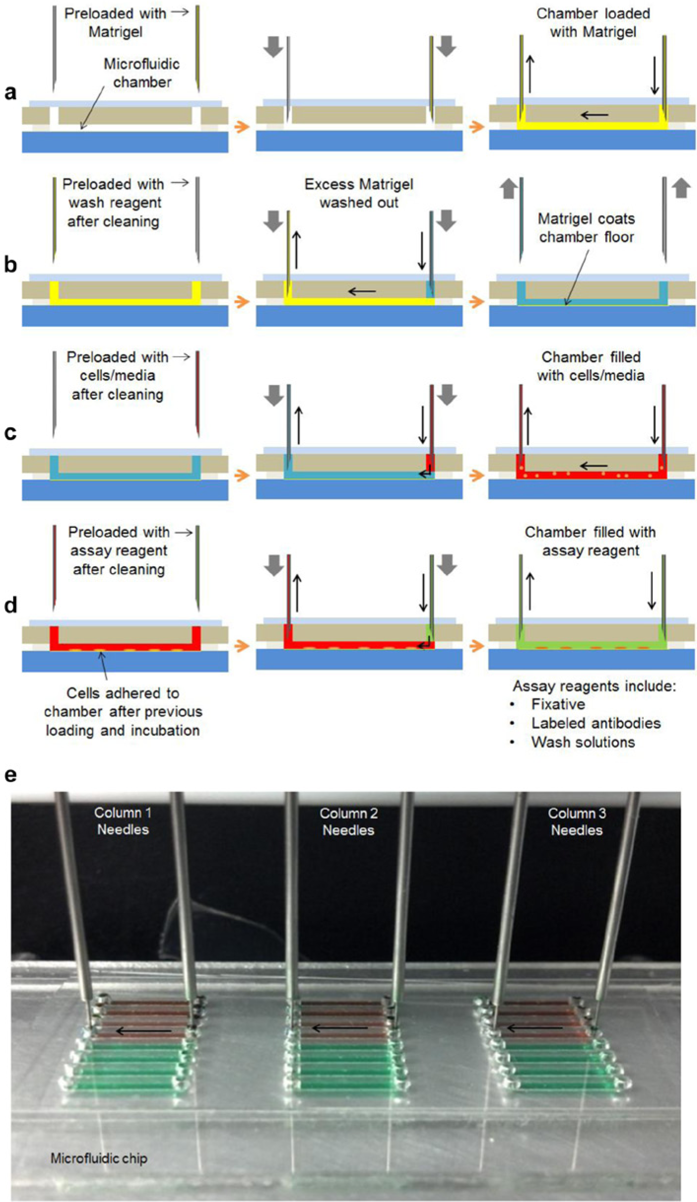
Schematic of automated multistep prototypical protocol. (
Before the start of an assay, the system and needles are cleaned thoroughly. The exteriors of the needles are cleaned with ethanol. The interiors are cleaned by aspirating and dispensing 500 µL of ethanol from a trough a total of three times. This is followed by a system flush of water (~1 mL) through the needles to remove residual ethanol. An automated washing step is also performed immediately prior to aspirating each new reagent. During these washing steps, the needles are stationed in the large wash trough. Water flows through the needles from the Nanodrop system water reservoir (to clean the inside surfaces) and fills the washing trough until the level rises above the bottom portion of the needles (to clean the outside surfaces). The water (~1 mL total) in the trough is repeatedly flushed away to prevent overflow and to prevent buildup of contaminants in the troughs.
Upon initialization, the system purges air from the tubing and fills tubes with water to increase accuracy by eliminating effects of gas compression in the tubing. To ensure reagents do not mix with the deionized water filling the whole fluidic system, an air gap is first aspirated into the fluid delivery needle, followed by the desired amount of reagent from the desired reagent well. When loading chambers with reagents, 6 µL is delivered to each 5 µL chamber. Thus, for one needle pair to deliver to all 24 microfludic chambers (i.e., all eight rows of all three chips), a total of 168 µL is aspirated (24 × 6 µL to fill chambers + 24 µL excess). The needles filled with reagent are then moved to the desired row of chambers on a microfluidic chip, lowered to pierce the evaporation barrier, and 6 µL is delivered to each of the three chambers per row in parallel.
Microchamber Preparation for Cellular Assays
To prepare the microfluidic chambers for cell capture, they are loaded with a 1:20 diluted Matrigel solution in Dulbecco’s Modified Eagle Medium (DMEM; Life Technologies, Grand Island, NY), maintained overnight at 4 °C and then washed with DMEM to remove excess Matrigel. Although a small contributor to background signal during fluorescence imaging, Matrigel is an effective and easy-to-use substrate for maintaining cells in microfluidic-based assays.23,24 The chambers are then loaded with cells that have been suspended in DMEM. Depending on the assay, this is typically followed by loading of standard media (control) or media containing a drug, and the chips are then incubated. After treatment, a wash step is conducted and cells are fixed, blocked, and labeled in successive steps in preparation for imaging and quantification. A detailed immunocytochemistry protocol is included in the
Comparison of Performance to Manually Operated Chips
Several assays were conducted on both the new platform (automated delivery of liquid via needles into plastic chips) and the original platform (manual delivery of liquid via micropipette into PDMS chips). The PDMS chips were fabricated according to Sun et al. 10 Liquids were manually introduced into the PDMS chips by inserting the pipette tip and forming a tight seal with the inlet hole. For each loading step, 5 µL of liquid was dispensed into the chamber, and the original contents were simultaneously absorbed by a Kimwipe placed in contact with the outlet hole. A slightly lower flow rate was used (~4 µL/s for manual pipetting vs. 1.67 µL/s for the robotic system) to fill the chambers. All other conditions were kept constant between the two platforms.
Reagent Carryover Assay
Red food dye (Kroger, Cincinnati, OH) diluted 1:150 in water was first loaded into a microfluidic chamber. Next, a wash step was performed by loading deionized water, causing displacement of the previous contents of the chamber, and allowing the water to sit for 2 min. Different numbers of wash steps (zero to four) were performed on different chambers. The assay was performed six times for each number of washes on each of the two platforms (robotically loaded plastic chips and manually loaded PDMS chips). To quantify carryover, the final contents of the microfluidic chambers were collected manually via pipette, and the absorbance of each sample was measured using a Nanodrop 2000 spectrophotometer (Thermo Scientific, Lafayette, CO) at a wavelength of 500 nm. Using Beer’s Law, the relative concentration was determined by dividing each absorbance by the absorbance of the zero wash sample ( Fig. 4a ).
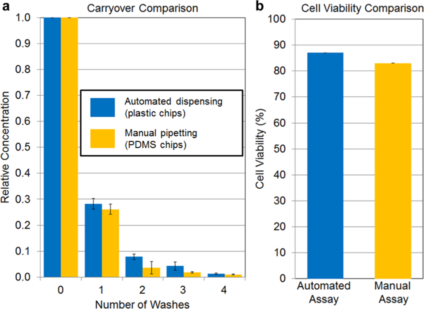
Quantitative comparison of carryover. (
Cell Viability Assay
Cell viability assays were performed with a cultured human-derived tumor-initiating cell line (NS 157) created from patient brain tumors commonly used in cancer stem cell biology and drug discovery.25,26 Cells were cultured according to methods described previously. 26 Prior to viability assaying, characteristic spheroid cell aggregates were broken down into single cells via enzymatic dissociation with TrypLE (Invitrogen, Carlsbad, CA) for 5 min at 37 °C and then spun down at 1200× for 5 min. The enzyme was removed and replaced with DMEM F-12 (Invitrogen), and spheres were triturated into single cells.
For each platform (manual and automated), cells at a concentration of 250 cells/µL DMEM are mixed 1:1 with Trypan blue (Life Technologies, Grand Island, NY) and then loaded into Matrigel-treated chambers. Images of the chambers were taken immediately with a Nikon TE2000S inverted fluorescent microscope with a charge coupled device (CCD) camera (Photometrics Cascade II, Tucson, AZ). For each platform, live and dead cells in four to five frames of each of the eight chambers imaged were counted and summed to assess viability. Counts were repeated by three independent raters (J.L., M.M.-S., B.K.).
Quantitative Target Inhibition Assay
Microfluidic chambers were first treated with Matrigel as described above. M229P melanoma cells were maintained in 10 cm petri dishes in a media of 10% fetal bovine serum 1% penicillin streptomycin (Invitrogen) at 37 °C 5% CO2. Cells were grown to near confluency and were harvested for experimentation. A quarter of the cells were replated. Cells take approximately 2 days to reach confluency. Just prior to cell loading into the microfluidic chip, the media were suctioned off and cells were lifted with 5 min exposure to a mild-trypsin substitute, TrypLE (Invitrogen). The cells were loaded into each chamber at a concentration of approximately 250 cells/µL. The chip was incubated for 30 min at 37 °C and 5% CO2. Eight chambers per condition were incubated in media supplemented with or without rapamycin (0, 5 nM, and 5 µM concentrations) for 1 h. Cells were then fixed, permeabilized, blocked, and labeled with a fluorescent antibody that recognizes phosphorylated (active) ribosomal S6 to assess available protein concentration in cells. The complete protocol is described in the
Images were taken along the length of each of eight treated and untreated chambers of the chip with a Nikon TE2000S inverted fluorescent microscope with a CCD camera (Photometrics Cascade II). Typically, four to five images were obtained per chamber. The MetaMorph image analysis system (Molecular Devices, Sunnyvale, CA) was used for quantification. This software enables overlay of DAPI images and fluorescein isothiocyanate (FITC) images to identify cells accurately and determine the intensity of FITC signal per intact cell. With these data, we constructed histograms of FITC intensity.
Results and Discussion
Design of the system was motivated by the desire to automate cell-based microfluidic chip assays, such as monitoring of multiple signaling protein expression levels that we previously developed for diagnostics to visualize the heterogeneity within and between tumors in clinical samples from glioblastoma patients. 10 Such measurements have great potential and clinical utility in personalized cancer diagnostics and treatments.
We adopted a pipette-based approach to minimize sample use and number of cells required while providing flexibility for diverse assays and a wide selection of cell treatment and readout conditions in each microfluidic chamber. The resulting platform enables parallel cell culture and quantification without human intervention on up to three microfluidic chips, each containing 24 chambers, for a total of 72 individually addressable chambers.
One of the key design challenges in automation was achieving reliable alignment (in x, y, and z directions) between the ends of the dispensing tips and the inlet and outlet ports of the microfluidic chips. The original chips were made from PDMS, which, although convenient for fabrication of microfluidic chips, undergoes significant, sometimes uneven, shrinkage upon curing that can displace microchannel ends from their designed locations. Furthermore, the soft, elastomeric nature of PDMS makes it difficult to create inlet and outlet ports that are perpendicular to the PDMS surface, thus introducing another source of error. PDMS has additional drawbacks in screening applications, such as its tendency to absorb many small molecules. 27 These issues are addressed by the multilayer chip design, incorporating a rigid plastic layer, reported here. The placement of alignment holes in the same rigid chip layer as inlet and outlet ports ensures high consistency of positioning.
Another key issue was the prevention of air bubbles from entering the chambers. Such bubbles can be created either when remating the dispensing tips to the chips between subsequent fluid delivery steps or by evaporation at inlets and outlets during the elapsed time between subsequent delivery steps. These issues were primarily solved by adding the evaporation barrier layer to the chip. This, in turn, required the use of sharp needles to pierce this layer. Several iterations of our robot dispensing tip, chip designs, and evaporation barrier designs were tested before finalizing the needle/chip interface and are described in
In our previously reported PDMS chips,10,23,24 the manually inserted pipette tip completely plugs the inlet hole so channel contents can be completely flushed out and replaced with the new incoming reagent. In contrast, in the current automated platform, the needle tips are much smaller than the size of the inlet hole, a geometry that creates a small dead volume. Comparing the effectiveness of washing steps for clearing residual reagents in a carryover assay, we observed only a slight increase in carryover despite the above difference ( Fig. 4a ). After three washes (which was found to be sufficient for the assays performed here), the carryover was found to be 4.3% ± 2.0%, compared with 1.85 ± 1.0% for the PDMS chips with manual pipetting. If lower carryover is needed for particular applications, additional wash steps can easily be incorporated and would not add significant time to the assay.
The plastic microfluidic chips and needle tips have different materials and geometry, which could affect cells, and therefore a cell viability assay was conducted to compare the new chips and automated dispensing platform with the previous, manually loaded PDMS chips. Viabilities for the two platforms were found to be comparable (i.e., 86.5% ± 0.2% and 83.5% ± 0.7%, respectively). A Student t test showed no significant differences in viability (p = 0.15; Fig. 4b ). Although the automated platform, in terms of carryover and viability, does not exceed the performance of the original platform, it does provide several potential advantages associated with automation, including reduced time and labor, reduced chance of human error, and increased throughput.
In addition to providing rigidity and positional accuracy of inlet and outlet ports, the acrylic layer of our chip limits this undesired evaporation of water from the chip. When the chips were covered with a new piece of polyurethane tape, evaporation was observed to be negligible over the time scales (minutes to several hours) during which the chips would be installed in the robotic fluid-handling platform.
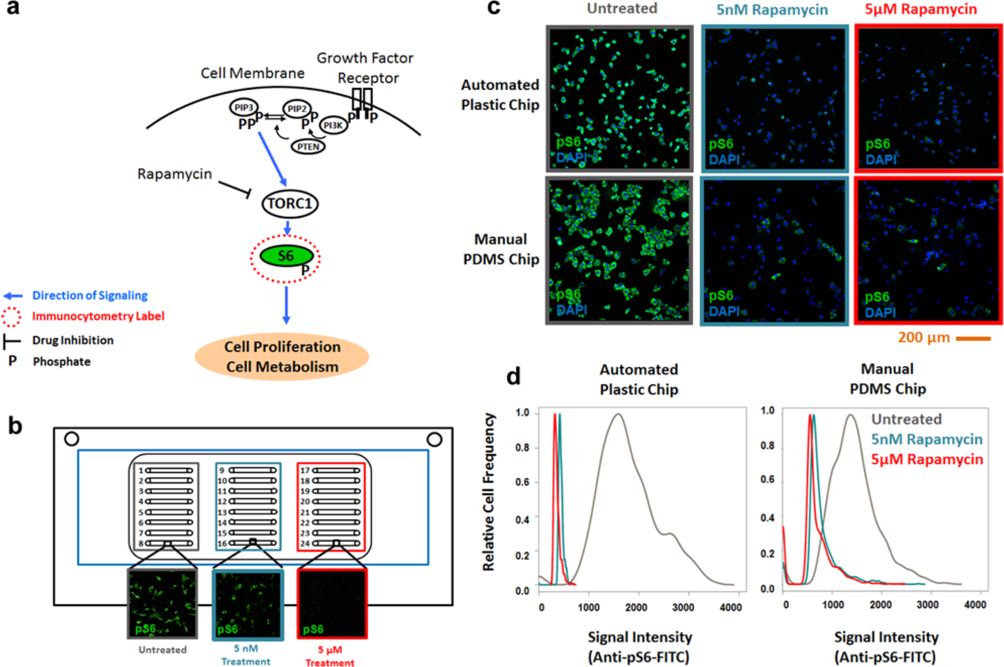
As a further measure of comparison of the performance of microfluidic platforms, a human-derived melanoma cancer cell line (M229P) was used to quantify target inhibition of the drug rapamycin on dephosphorylation of the ribosomal S6 protein. Rapamycin and its analogues are known to have antiproliferative effects in some cancer cells by inhibiting activation of the mammalian target-of-rapamycin (mTOR) through TOR complex 1, TORC1, which is a complex primarily of mTOR, mLST8, and regulatory associated protein of TOR (Raptor), a complex pathway known to be highly active in many cancers by regulating cell proliferation and metabolism. A second complex, mTORC2, is a complex of mTOR, mLST8, and rapamycin insensitive companion of TOR (Rictor), which is involved in cytoskeletal reorganization.28,29 Downstream activation of mTOR complex 1 (TORC1) can typically be monitored by phosphorylation of the S6 protein, the downstream target of TORC1 signaling (
Fig. 5a
). Indeed, both concentrations of rapamycin tested (5 nM and 5 µM) caused a significant reduction in pS6 expression compared with untreated cells (
Fig. 5c
–
d
). Quantification of drug response at the micromolar range is suitable for drug-screening applications, whereas quantifying drug response at a concentration in the nanomolar range mimics that which may occur at physiological relevant conditions.30,31 The distribution of expression in cells for untreated, 5 nM rapamycin, and 5 µM rapamycin was found to be similar between the automated loading with plastic chips (~350 cells) and manual loading of PDMS-based chips (~300 cells), suggesting the automation and changes in the chip architecture did not adversely affect assay performance. Results of a 96-well assay are included in
Comparison of quantitative target inhibition assay. (
The success of the above immunoassays suggests that the platform will also be suitable for other cell-based assays of varying throughput. For example, one could measure the response to more concentrations to construct detailed quantitative IC50 profiles, investigate sensitivity to drug permutations, or investigate the role of cell-to-cell heterogeneity in treatment response and drug resistance.
Although the system is able to successfully provide automated immunoassays with a performance similar to nonautomated approaches, there are several aspects of the system that could by improved in future studies. Throughput is key to scalability. The throughput is related both to the number of samples simultaneously accessible and the speed at which operations are performed. The number of samples could be increased by developing chips that make more efficient use of available chip area. We estimate that up to four times the number of rows and columns could fit onto each microscope slide–sized chip, thus expanding the number of chambers per chip to 96, and 288 total chambers in the three chips that can simultaneously fit on the automated stage at one time. Mechanically, the Nanodrop system on which we built the system has relatively slow linear actuators. Faster actuators and optimization of motion algorithms to prevent frequent homing of the robot could significantly reduce the time to deliver reagents to chips and thus increase the throughput of the overall system. The limiting time would be the actual flow time currently used to deliver liquid into each chamber. Even this flow limitation could be addressed by designing a system with more simultaneously actuated needles to increase the parallelism of the dispensing process. The downstream imaging and analysis could be improved by the use of high-throughput whole-slide image and analysis tools such as the Aperio ePathology (Vista, CA) and the Leica Ariol microsystems (Buffalo Grove, IL), which are finding routine use in biological and pathology laboratories.32,33 To integrate this automated system with these slide-handling analysis tools, the size and format of the chip might require some adjustment.
The overall platform has a size similar to a piece of benchtop laboratory equipment and can readily fit on a benchtop or inside a standard tissue culture hood. The robotic pipetting system employed here was purchased for approximately $50,000, including software and external syringe pumps, but we expect that significant reductions would be possible by developing a customized system in which extraneous features and functions are omitted. Incremental improvements can be made in throughput, chip design, and interoperability with existing automated slide scanners, image-processing tools, and other emerging microfluidic systems as a highly efficient benchtop laboratory cell analysis system for research, drug discovery, or diagnostics. 34
Conclusions
Building on a microfluidic platform comprising arrays of individually addressable chambers of immobilized cells in PDMS microfluidic chips, 10 we developed an automated platform based on a commercial high-accuracy pipetting robot to automate the cell- and liquid-handling operation sequences needed to perform quantitative immunocytochemistry. We designed an improved microfluidic chip from low-cost materials and fabrication processes and included nonpermeable elements to prevent loss of moisture or introduction of air during lengthy multistep assays or longer-term storage. The choice of rigid plastic for one of the chip layers provides precise mechanical alignment and repeatable positioning that is necessary for automation. Fluid transfers are performed by pairs of needles operating in a coordinated fashion to aspirate samples and reagents of minimal volumes from conventional well plates and dispense them into the microfluidic chambers at a well-controlled flow rate. The previous contents of the microfluidic chambers are efficiently collected as the new liquid is introduced. Sharp tips on the needles pierce the low-permeability evaporation barrier that forms the top layer of the chip. The use of robotics is very flexible, enabling a wide variety of treatment and/or readout conditions to be applied in each chamber.
We evaluated the performance of the fluid-handling system by comparing the performance of several assays on the new platform with assays performed manually with PDMS chips. In particular, carryover and cell viability were comparable to the previous platform. In addition, a proof-of-concept quantitative molecular treatment response experiment showed similar results across the two platforms, suggesting that the addition of automation (and the advantages that are generally associated with this) did not adversely affect the microfluidic assay platform.
This platform performs high-sensitivity assays for drug response and diagnostics to ultimately fulfill a vital role in fulfilling the promise of personalized medicine.
Footnotes
Acknowledgements
We would like to thank Dirk Williams and Darin Williams for the design and fabrication of mechanical parts to modify the Nanodrop system, Dr. Chiyun Xia for assistance with programming, Kevin Quinn for assistance with photographs of the system and chips, and Dr. Christian Behrenbruch and Dr. Winny Tan for valuable contributions to system and chip design. Human-derived brain tumor stem cell line and rapamycin used were generous gifts of Dr. Harley Kornblum of the Department of Pediatrics, Neurology and Molecular and Medical Pharmacology, David Geffen School of Medicine, University of California, Los Angeles (UCLA). The human-derived melanoma cell lines were a generous gift of Dr. Antoni Ribas of the Department of Hematology Oncology, David Geffen School of Medicine, UCLA. Useful advice and comments from Dr. Thomas Graeber of the Department of Molecular and Medical Pharmacology, David Geffen School of Medicine, UCLA, are greatly appreciated. The use of the Metamorph imaging and analysis was generously provided by Dr. Hsian-Rong Tseng from the Department of Molecular and Medical Pharmacology, David Geffen School of Medicine, UCLA. All experiments with human cells were conducted under protocols approved and overseen by the Institutional Review Board of the UCLA Office of Protection of Research Subjects.
Declaration of Conflicting Interests
The authors declared no potential conflicts of interest with respect to the research, authorship, and/or publication of this article.
Funding
This work was funded in part by the California Institute for Regenerative Medicine (RT1-01022-1).
References
Supplementary Material
Please find the following supplemental material available below.
For Open Access articles published under a Creative Commons License, all supplemental material carries the same license as the article it is associated with.
For non-Open Access articles published, all supplemental material carries a non-exclusive license, and permission requests for re-use of supplemental material or any part of supplemental material shall be sent directly to the copyright owner as specified in the copyright notice associated with the article.