
Abstract
While potentially powerful, access to molecular diagnostics is substantially limited in the developing world. Here we present an approach to reduced cost molecular diagnostic instrumentation that has the potential to empower developing world communities by reducing costs through streamlining the sample preparation process. In addition, this instrument is capable of producing its own consumable devices on demand, reducing reliance on assay suppliers. Furthermore, this instrument is designed with an “open” architecture, allowing users to visually observe the assay process and make modifications as necessary (as opposed to traditional “black box” systems). This open environment enables integration of microfluidic fabrication and viral RNA purification onto an easy-to-use modular system via the use of interchangeable trays. Here we employ this system to develop a protocol to fabricate microfluidic devices and then use these devices to isolate viral RNA from serum for the measurement of human immunodeficiency virus (HIV) viral load. Results obtained from this method show significantly reduced error compared with similar nonautomated sample preparation processes.
Keywords
Introduction
Automated instruments have significantly improved diagnostics in the developed world by increasing patient throughput and decreasing diagnostic variability caused by human interaction.1,2 Often times, these automated instruments are complex “black box” systems where the operational mechanisms are hidden, making the instrument appear simple. However, such systems typically require expensive service contracts, specially trained operators, and instrument-specific disposables.3,4 In many developed countries, the benefits of repeatable data and the increased throughput of the black box instruments justify the costs. Unfortunately, in low-resource settings, the cost and accessibility to suppliers often limit acquisition, operation, and support of these instruments. 5 Furthermore, such instruments are typically inflexible, prohibiting users from modifying or adding operational protocols as new diagnostic needs arise.
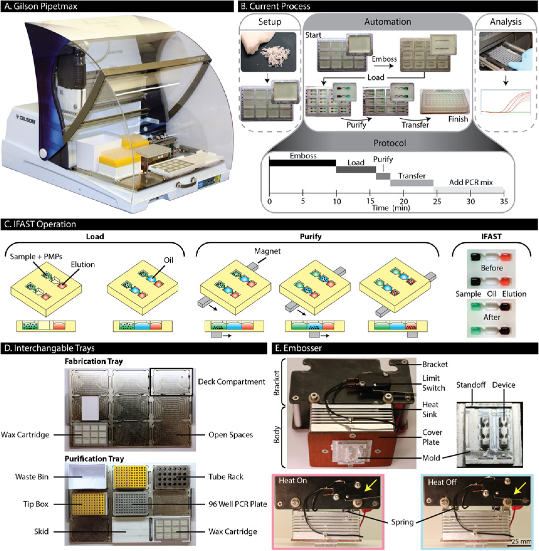
In this work, we address these needs through the development of a new molecular diagnostic instrument. This instrument, which is based on a commercial automated liquid handler (Pipetmax [Gilson, Middleton, WI]; Fig. 1A ), leverages on-board wax device manufacturing and a simplified sample preparation technique, pioneered by our laboratory, to minimize costs and maximize utility. In this initial demonstration, we integrate microfluidic device fabrication, viral RNA isolation, and reverse transcription and quantitative polymerase chain reaction (RT-qPCR) setup onto one instrument ( Fig. 1B ). It should be noted that this functionality is similar in scope to other automated sample preparation systems currently used in molecular diagnostics, such as the Ampliprep (Roche, Indianapolis, IN) or m2000sp (Abbott, Abbott Park, IL). Our system maintains the traditional automation advantages of operational simplicity and repeatability, while doing so in an “open-source” environment. This open system enables users to expand the functionality of the instrument and develop new assays as new diagnostic demands arise. In addition, the open system allows users to visually verify that the machine is operating as expected and that all components may be operated manually in the event of a mechanical or power failure (albeit with some reduction in throughput and precision).
(
We use a relatively new sample preparation technique, immiscible filtration assisted by surface tension (IFAST), to dramatically simplify the process workflow, thus reducing the complexity of automation infrastructure required ( Fig. 1C ). IFAST is a method of purification that relies on surface tension and immiscibility to separate aqueous phases using an oil barrier. 6 The IFAST device is a microchannel consisting of three interconnected wells containing sample, oil, and elution buffer. Each well is connected via a small constriction designed to stabilize these immiscible phases side-by-side. Initially, the sample is mixed with paramagnetic particles (PMPs) that bind to the analyte of interest, viral RNA in this case. By sliding the device over a magnet, the PMPs are collected and drawn through the oil and into the elution buffer. This intermediate oil well serves as an immiscible barrier, preventing unbound sample from carrying over into the elution buffer. IFAST has been previously used in an automated setting to extract protein from samples in a seroconversion assay. 1 In addition, various configurations of IFAST have been manually fabricated in wax (data not shown), demonstrating that viral RNA can be extracted from multiple samples in parallel in a simple, efficient, and repeatable manner.
Because viral nucleic acid extraction is critical for many molecular diagnostic assays, we chose to focus on human immunodeficiency virus (HIV) viral load quantification, through RNA extraction, as an initial proof-of-concept application. Frequent monitoring of viral load is necessary to successfully manage antiretroviral therapy (ART) as mutations in the HIV virus can lead to ART drug resistance. 7 With proper management, ART can be quite successful as clinicians can adjust ART regimens as specific drug resistances develop. 8 Unfortunately, viral load quantification is often prohibitively expensive in the developing world 9 (cost ranges from $50 to >$100) and is frequently not performed. Sample preparation (the extraction of viral RNA from patient plasma) contributes significantly to the operational complexity (and associated cost) of traditional sample preparation protocols. 10 Automated sample preparation systems must be capable of performing complex, multistep solid-phase extraction (SPE) processes.11,12 Thus, a reduction in sample preparation complexity could significantly reduce the total viral load quantification cost, greatly improving access to this critical molecular diagnostic test.
Materials and Methods
Instrument Overview
The automated liquid handler is designed to accommodate interchangeable trays, each consisting of a 3 × 3 array of standard SLAS well plate compartments ( Fig. 1D ). We have developed two custom trays for this application: (1) a fabrication tray that houses cartridges for embossing devices and (2) a purification tray, which houses all necessary components and reagents for isolating RNA from samples and setting up a well plate for RT-qPCR. While using the fabrication tray, a custom embossing unit (termed the embosser) is attached to the pipetting head of the robot. While using the purification tray, the embosser is removed and standard eight-channel p20 and p200 pipette heads are used. The robot is programmed using icon-based software (Protocol Builder; Gilson). After RNA isolation and RT-qPCR setup are complete, the loaded PCR plate is manually transferred to a real-time thermal cycler to complete the viral load assay.
Wax Setup
Wax IFAST devices ( Fig. 1C ) are embossed in cartridges filled with Sasolwax #B7347 (Sasol Wax, Hayward, CA), a wax that is both ductile and stable at room temperature, for extended periods of time. Wax is used because of its low cost, easy manipulability, and relatively low melting point (as compared with many plastics). To ensure the wax does not pull out of the cartridge during embossing, the walls of each compartment have an overhang, such that the wax blanks are unable to be lifted vertically from the cartridge. Each cartridge is made from 3.2-mm-thick aluminum and matches the footprint of a standard SLAS well plate (85.5 × 127.8 mm). At each end of the cartridge is a row of eight holes that are spaced to accommodate tips on an eight-channel pipette head (9-mm spacing), such that the pipette head can be directly used to draw the cartridge across magnets to actuate the IFAST devices. Within each cartridge is a 3 × 4 array of compartments, each measuring 25 mm long, 19 mm wide, and 3 mm deep. The compartments are filled with wax by heating the cartridge to 115 °C and melting wax directly in the compartments. The cartridges are passively cooled at ambient temperature and then secured to the fabrication tray ( Fig. 1D ) using screws at opposing corners.
Embossing Setup
To prepare the robot for fabrication, the embosser is attached to the pipetting head and a wax-filled cartridge is placed into the liquid handler. The embosser ( Fig. 1E ) is a two-part unit consisting of a bracket and a body. The bracket enables attachment to the liquid handler head using the existing hardware. The body is loosely mounted to the bracket through vertically slotted holes but mechanically separated from the bracket with springs. The body consists of an aluminum heat sink, a Peltier heater (not shown) (#TEC1-12708; HB Corporation, Shanghai, China), an interchangeable aluminum mold, and a cover plate. The cover plate attaches the mold and the heater onto the heat sink. The heater is powered with 3 A and 18 V from a DC power supply (#YH-305D; Yihua, GuangZhou, Guangdong, China), controlled through a limit switch affixed to the embosser. The limit switch is mounted to the embosser bracket such that heating is induced when the springs between the body and bracket are compressed. The mold contains two IFAST devices, with each device consisting of three wells (sample, oil, and elution well). The wells are 3.3 mm wide, 4.5 mm long, and 2.5 mm tall. Between each well is a constriction that is 1.2 mm wide, 1.5 mm long, and the same height as the wells. All of the features, except the constrictions, have a 7° draft to facilitate mold removal. The mold depth during embossing is controlled by standoffs on the side of the mold. The standoffs bottom out on the cartridge, beside each compartment, to leave a 0.4-mm wax barrier between the mold and the cartridge (which serves as the bottom of the device). It is critical to control the thickness of the bottom of the IFAST device (total thickness including aluminum <1 mm) to ensure consistent spacing between the device bottom and the magnet, located under the cartridge. This spacing influences the magnetic force required to successfully actuate the IFAST device (i.e., if the device bottom is too thick, the magnet will be too far from the PMPs to successfully draw them through the oil barrier, and RNA recovery will be adversely affected).
Embossing Protocol and Characterization
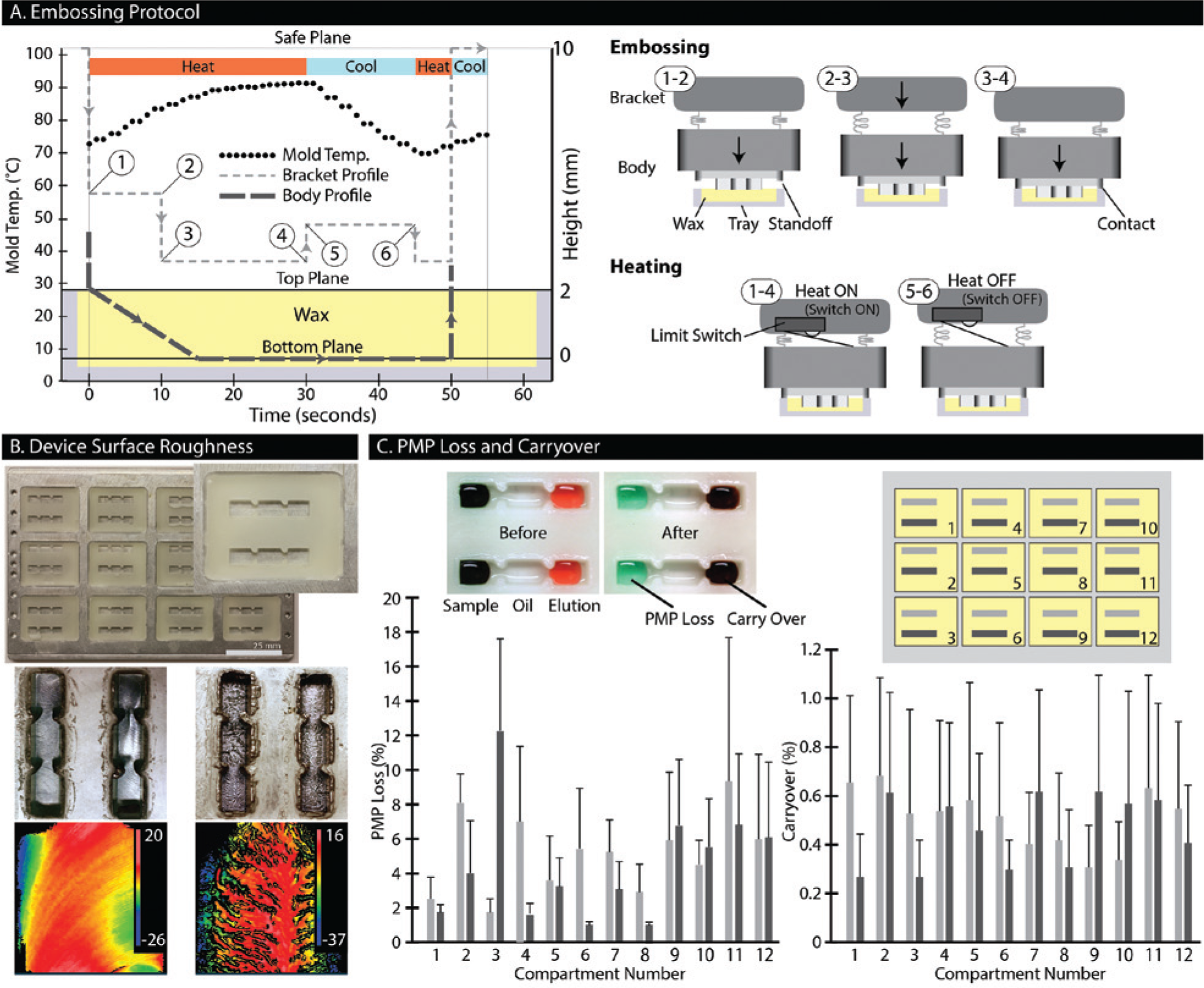
To successfully emboss devices with well-defined features, the thermal profile of the embossing process was optimized. This protocol is shown schematically in
Figure 2A
, where the smaller dashed line represents a reference point on the bracket, and the bold dashed line represents a point on the tip (bottom) of the mold. Importantly, the springs allow the body to move independent of the bracket, and the dashed lines of
Figure 2A
demonstrate the relative motion between each component. To start, the embosser is lowered until the mold contacts the wax and continues to lower an additional 2 mm, thereby compressing the springs. This compression triggers the limit switch, activating the heater. The heat softens the wax while the springs press the mold into the wax. After 10 s, the mold has depressed partially into the wax and the bracket is lowered an additional 1 mm to recompress the springs and ensure that the limit switch remains triggered. Supplying heat for an additional 20 s (total embossing time of 30 s) allows the standoffs to bottom out against the cartridge, thus completing the embossing. At this point, the embosser is lifted by 0.5 mm to de-trigger the limit switch, while simultaneously maintaining compression in the springs to prevent de-molding. For the next 15 s (total embossing time of 45 s), the mold is passively cooled, allowing the wax to solidify. The bracket is then lowered by 0.5 mm to retrigger the limit switch. The mold is warmed for 5 s (total embossing time of 50 s) and then completely removed from the wax (see
(
To confirm that this molding protocol is optimal, the embossed wax devices were characterized based on surface roughness of the device. To measure surface roughness, wax devices were removed from the cartridge, sputtered with gold for 50 s at 45 mA, and then imaged in a white light interferometer (New View 7300; Zygo, Middlefield, CT). The roughness is reported as the root mean square (RMS) going lengthwise across the channel.
Purification Protocol and Characterization
In preparation for purification, the fabrication deck is swapped for the purification deck (
Fig. 1D
). The purification deck houses all necessary components for the assay, including waste bin, tip boxes, reagent tube rack, and a skid for integrating the previously embossed wax cartridges. The skid provides a smooth surface that spans two of the tray compartments. Embedded in the center of the skid is a row of magnets (#BX041-N52; K&J Magnetics, Pipersville, PA) that actuate the IFAST devices as the cartridge is drawn over. During this process, the PMPs are magnetically captured and traversed from the sample well, through the oil well, and into the elution well (
Fig. 1C
; see
Device performance was benchmarked based on recovery yield and purity. To determine recovery yield of PMPs alone, we attached Alexa Fluor 488–conjugated secondary antibodies (Life Technologies, Grand Island, NY) to Protein G–coated PMPs (Protein G Dynabeads; Life Technologies) by incubating them together for 15 min at room temperature in phosphate-buffered saline (PBS) with 0.01% Tween-20 (#P1379; Sigma-Aldrich, St. Louis, MO). After removing the supernatant, PMPs were resuspended in 20 µL RIPA lysis buffer (#20188; Millipore, Billerica, MA) and loaded in the sample well of the device. Wells were filled sequentially, using only one tip on the pipetting head. Next, 20 µL Buffer MFE (#955235; Qiagen, Valencia, CA) was loaded into the elution well, and 15 µL FC-40 oil (#F9755; Sigma-Aldrich) was loaded into the middle well, in that order. After purifying the PMPs by drawing the cartridge across the skid magnet, the contents of the sample well were removed and resuspended in clear microfuge tubes with 180 µL PBS. The tubes were measured for fluorescence using a Qubit Fluorometer with an excitation wavelength of 430 to 495 nm (#Q32866; Life Technologies). The results were compared with a standard curve relating PMP concentration to fluorescent intensity. To determine purity, the sample well was filled with Buffer MFL (Qiagen) supplemented with 2 µL PMPs (#MD1471, MagneSil KF; Promega, Madison, WI) and acridine orange at concentration of 10 µg/mL to serve as a nonspecific “background.” The elution well was filled with MFE elution buffer. After purification, the contents of the elution well were removed, resuspended, and quantified in the same fashion as the PMP loss experiment to determine the concentration of acridine orange that had been nonspecifically carried over during the IFAST operation.
HIV Viral-Like Particle Purification
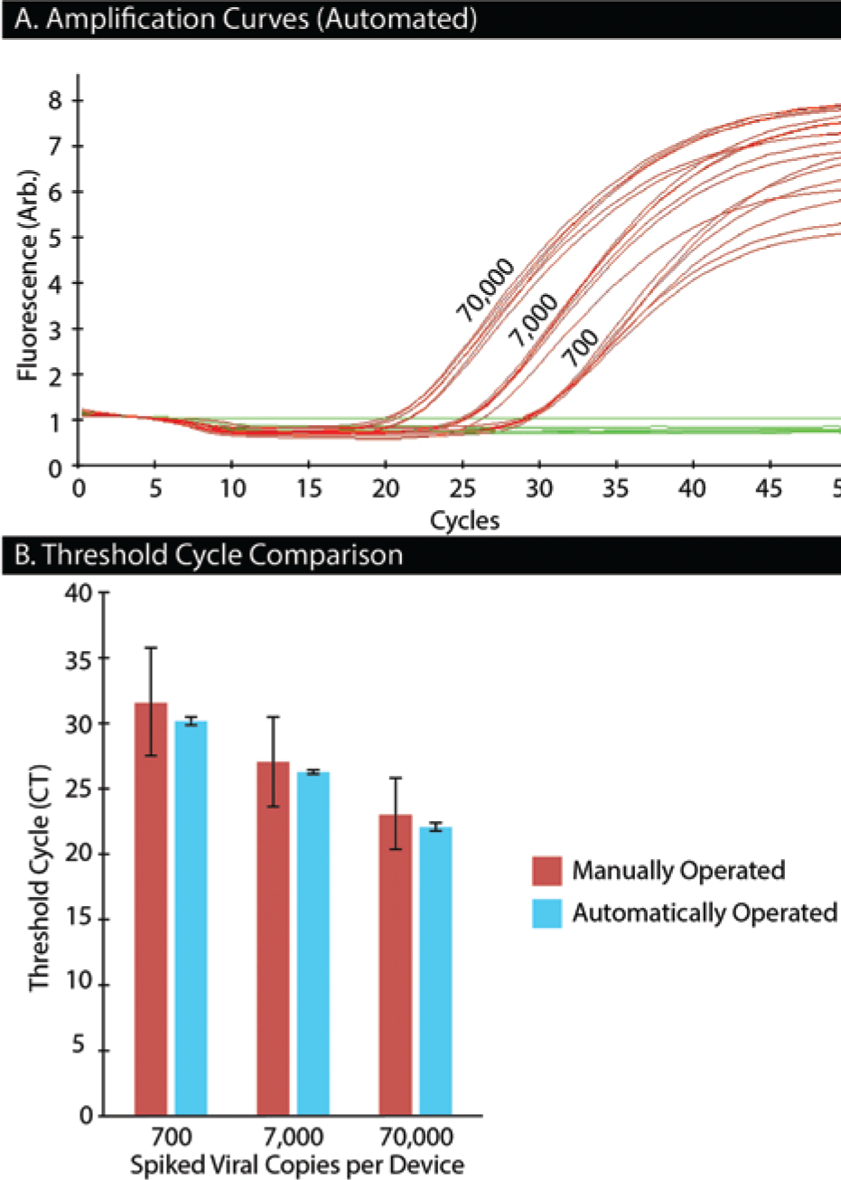
Using the same devices, volumes, and filling protocol as previously described, we isolated viral RNA to measure viral load. To simulate viral load at various quantities, HIV viral-like particles (gift of Dr. Nathan Scherer) were spiked into fetal bovine serum (FBS) at concentrations of 700, 7000, and 70,000 copies per 10 µL to create mock patient samples. Note that these sample concentrations were necessary due to volume limitations of the sample well. However, similar work has demonstrated that enlarging the sample well lowers the limit of detection to 50 copies per milliliter.7,13 These samples were loaded into the tube rack, and the liquid handler mixed the samples 1:1 with a mixture of MFL lysis buffer and PMP stock solution (which contained 2 µL PMPs/8 µL MFL). The samples were incubated for 5 min at room temperature, and then the contents were automatically transferred to the sample wells of the wax IFAST devices. As previously described, the PMPs were purified via IFAST into an elution well containing MFE elution buffer. After purification, 10 µL of the eluent was transferred to a 96-well PCR plate, which was then mixed 1:1 with a solution containing RT-qPCR one-step Master Mix (Taqman Fast Virus 1-Step Master Mix; Life Technologies) and ANRS probe (#4332079, Custom TaqMan Gene Expression Assay; Life Technologies). 14 At this point, the PCR plate was removed from the liquid handler and placed in a real-time thermal cycler (LightCycler 480; Roche) for amplification. The amplification protocol was 50 °C for 8 min, 95 °C for 30 s and then 50 cycles of 95 °C for 1 s, and 60 °C for 20 s (the ramp rate was 4.4 °C/s). Each concentration was repeated six times (n = 6), and we obtained copy numbers by comparing threshold cycle (CT) values from these samples with those obtained from standards with known copy numbers. Results were compared with a similar protocol in which IFAST devices were manually fabricated, loaded, and operated.
Results and Discussion
Wax Device Embossing Characterization
Each step in the embossing protocol plays a significant role in the device quality and overall fabrication time. This process was optimized for our particular system, but some steps may be streamlined or omitted after additional development. For instance, in our configuration, the springs were recompressed 10 s into the embossing to ensure the limit switch remained triggered. The recompression was necessary because the thickness of the wax was 2.5 mm, while the distance where the limit switch was triggered (without colliding with the bracket) was 1.5 mm. Changing components to give the limit switch a larger triggering distance or removing it all together would simplify the embossing step. Furthermore, the temperature of the mold at the start of each embossing cycle plays a significant role in the final quality of the device. Specifically, as more devices are embossed, the embossing step can be shortened. Approximately 30 s are required to ensure complete embossing of the wax when the heat sink starts at room temperature. However, as more devices are embossed, the temperature of the mold and the heat sink increases due to heat retention. After a few embosses, the heat sink reaches a steady-state operating temperature (shown by the dotted line in Fig. 2A ). At steady state, the temperature cycles from 70 °C to 90 °C, and embossing can be completed in 20 s. Even though the embossing was completed in 20 s, there were no adverse effects caused by leaving the embosser on for an extra 10 s. However, shortening the total emboss cycle time will improve overall assay throughput.
The cooling and rewarming steps directly affect removal of the mold and were essential for fabricating a repeatable device. In addition, we found that the cooling and rewarming steps are interdependent. For example, a cooling time of 15 s required a rewarming time of 5 s to remove the mold without breaking features. However, a cooling time of 90 s required a rewarming time of 45 s, which allowed the mold to be removed more easily, without needing to secure the cartridge to the tray. We hypothesize that there is an optimum temperature to remove the mold, where the wax is soft but well formed as opposed to completely solid or melted. Deviating from this optimal temperature was shown to have adverse effects on the outcome of the device. When the mold was too cold, it would stick to the wax, causing unwanted adhesion to either the cartridge or tray, ultimately breaking device features. On the other hand, if the warming step was disproportionally too long compared with the cooling step, the wax around the mold would over soften and result in high surface roughness.
We characterized the effects of minute temperature variations on the surface roughness of the wax IFAST device surface ( Fig. 2B ). When a channel was embossed as described in the optimized protocol, the RMS surface roughness was 1.6 µm, which was an artifact of the machining marks on the mold. However, when the duration of the final warming step was increased by 5 to 10 s, without altering the cooling step, the surface roughness increased to 10.5 µm. Conversely, when the duration was decreased, features would break off, or a wax would peel from the bottom of the channel. High surface roughness was also encountered when completely releasing the compression in the springs during the cooling step. We speculate that removing the compression forms voids underneath the mold, which do not warm up enough to reflatten during the warming step. While we anticipate that many mechanisms contribute to higher surface roughness, we have experimentally determined that this high surface roughness is detrimental to the operation of the device. Although we only quantitatively characterized visually smooth devices, the rough surfaces caused PMPs (often a majority) to become trapped during actuation.
Purification Characterization
We characterized PMP recovery yield and nonspecific carryover for an embossed IFAST device ( Fig. 2C ). PMP loss is characterized as the amount of fluorescent antibody-tagged PMPs remaining in the sample well after purification. Three cartridges of stamped devices (24 devices per cartridge) produced an average PMP loss of 4.8% with a standard deviation of 2.8%, where the highest observed loss was 18% (n = 72). The increased PMP loss was likely due to surface roughness resulting from the non–steady-state embossing of devices. Nonspecific carryover was quantified by measuring the amount of acridine orange in the elution well after purification. We observed that our devices had an average carryover of 0.48% (by volume) with a standard deviation of 0.51%, where the highest observed carryover was 1.58% (n = 72). These numbers are consistent with past performance involving RNA isolation and IFAST. 6 Importantly, we found that this level of purity was sufficient for efficient RT-qPCR amplification and detection.
We demonstrate a diagnostic application by measuring human immunodeficiency virus (HIV) viral load from mock patient samples. The liquid handler was prepared by removing the embosser and exchanging the fabrication tray with the purification tray. The liquid handler automatically mixed samples (by pipetting), dispensed them into the IFAST devices, purified the PMP-bound viral RNA, and set up the RT-qPCR reaction. No speed control was available within the software during the time of experimentation, so the devices were drawn across the magnet on the skid at full speed in increments of 2 mm with a 3-s pause between each motion. The pause allowed the PMPs to aggregate and stay within the magnetic field, thus minimizing loss of the PMP-bound RNA. After purification, the eluted sample was transferred to a 96-well PCR plate and mixed with RT-qPCR master mix. At this point, the plate was manually transferred from the liquid handler to a real-time thermal cycler for RT-qPCR ( Fig. 3A , B ). For comparison, a second purification was performed manually using wax IFAST devices. Comparing the threshold cycle (CT) values from both methods of purification revealed that the automated purification was, on average, one to two cycles lower than the manual purification, suggesting a higher level of RNA recovery (although not statistically significant). Moreover, the standard deviation observed from the automated purification was approximately 10-fold lower than the corresponding manual method, demonstrating the high level of precision of the automated platform.
(
Many automated systems for diagnostic applications are black box instruments, limited to few applications/assays and designed to discourage user modification. Conversely, our system is an open system that is adaptable to a wide range of user-definable assays (previously IFAST has been used to isolate cellular, protein, DNA, and RNA analytes). The user can visually verify that the instrument is functioning as expected and manually operate any component that has failed. The modularity of this system and the use of interchangeable trays enable the user to utilize custom protocols and components. If desired, developed protocols can be “locked,” preventing inadvertent modifications by less experienced users. We demonstrated the utility of the system by fabricating IFAST devices and performing HIV viral load quantitation with a high degree of operational precision. Our current cost of goods per test is 78 cents, where the device cost is less than 1 cent and the reagent cost (including lysis buffer, PMPs, oil, and elution buffer) is approximately 78 cents (based on retail price). With regard to labor, fabrication of a tray of devices takes ~5 min of manual labor (setup, heating, cooling, etc.) and 10 minutes of automated time for embossing (with no further input from the operator) ( Fig. 1B ). Purification of the RNA requires ~5 min of setup time and 25 min of instrument time. The instrument time can be further broken down into 6 min to load the cartridge, 2 min to purify, 6.5 min to transfer the samples to a PCR plate, and 10.5 min to add PCR mix to each well. However, the instrument is not limited to this specific application. The embossing capabilities presented here are amenable, without variation, to a variety of molds, enabling design and manufacture of custom devices. In addition, the tray design makes it conceivable to employ a heating element and a fluorescent detector to enable RT-qPCR (or similar analytical reactions) directly on the tray, potentially making this instrument a complete tool for fabricating, preparing, and analyzing a sample.
In conclusion, we have demonstrated the ability of a single instrument to both fabricate the assay devices and to perform high-precision sample preparation and RT-qPCR setup. As an example, we developed an assay for HIV viral load quantification, leveraging a new isolation technology (IFAST) to reduce the overall complexity of the assay. This reduction in complexity enables the use of a simple automated liquid handler rather than a more expensive and less adaptable “custom” piece of equipment with greater complexity. Device fabrication was optimized, such that high-quality wax IFAST devices were produced rapidly and repeatedly. RT-qPCR data (performed on a standard thermal cycler) demonstrated that RNA was extracted with high recovery yield and purity relative to a similar manual process. We anticipate the development of additional diagnostic assays on this platform, including complete sample-to-answer assays where the detection/quantitation process is integrated directly on the platform itself. In the future, we hope that the low cost and “open-source” flexibility of the platform will help to improve access to molecular diagnostic techniques, particularly in the developing world where the cost of diagnostic instrumentation often limits access.
Footnotes
Declaration of Conflicting Interests
The authors declared the following potential conflicts of interest with respect to the research, authorship, and/or publication of this article: David J. Beebe holds equity in Salus Discovery, LLC, Bellbrook Labs, LLC, and Ratio, Inc. Scott M. Berry holds equity on Salus Discovery, LLC.
Funding
The authors disclosed receipt of the following financial support for the research, authorship, and/or publication of this article: This work was supported by the Bill and Melinda Gates Foundation through the Grand Challenges in Global Health Initiative.
References
Supplementary Material
Please find the following supplemental material available below.
For Open Access articles published under a Creative Commons License, all supplemental material carries the same license as the article it is associated with.
For non-Open Access articles published, all supplemental material carries a non-exclusive license, and permission requests for re-use of supplemental material or any part of supplemental material shall be sent directly to the copyright owner as specified in the copyright notice associated with the article.