
Abstract
Study Design:
Biomechanical study.
Objective:
Cross-links are a type of common clinical spinal instrumentation. However, the effects of the position and number of cross-links have never been investigated in long-segment spinal fixation, and the variables have not been optimized. We conducted an in vitro biomechanical study by using a porcine long-segment spinal model with 5 different crosslink configurations to determine the optimal construct for clinical practice.
Methods:
Five modalities with paired segmental screws from T15-L5 were tested in 20 porcine spines. The spines without cross-links composed the control group, Group A; those with a single cross-link from L2-3 composed Group B; those with 2 cross-links from L1-2 and L3-4 composed Group C; those with 2 cross-links from T15-L1 and L4-5 composed Group D; and those with 3 cross-links from T15-L1, L2-3 and L4-5 composed Group E. Spinal stiffnesses in flexion, extension, lateral bending, and axial rotation were compared among 5 different cross-link configurations in 5-level porcine spinal units.
Results:
Flexional, extensional and lateral bending stiffnesses did not significantly change with an increasing number of cross-links or positions in the construct. Axial stiffness was significantly increased with 2 cross-links compared to one (P < 0.05) and with placement more distant from the center of the long spinal fixation construct (P < 0.05).
Conclusions:
Two cross-links individually placed proximal and distal from the center of a construct is an optimal and efficient configuration to achieve biomechanical stability in non-rigid lumbar spines undergoing long-level fixation.
Introduction
Long-segment instrumented spinal fusion is commonly performed in patients with coronal or sagittal imbalance resulting from idiopathic, congenital or degenerative scoliosis.1-3 The aims of the operation are to correct the imbalance, prevent curve progression and achieve solid arthrodesis.4-6 Pedicle screw instrumentation has been suggested to have better clinical efficacy than hook or hybrid constructs. 2
Cross-links are a commonly used type of clinical spinal instrumentation, and biomechanical investigations on short-segment fusion have revealed that the stiffness increases only in axial rotation and does not increase in flexion, extension or lateral bending, even when an increased number of transverse cross-links are used concomitantly.7-9 Other cadaveric biomechanical studies have shown increased stiffness not only in rotation but also in the other measured directions.10,11 Different configurations of cross-links and segmental screw constructs have been compared for long-segment fusion. Nakajima et al. compared conventional transverse cross-links with cross-links passing through the spinous process in a 5-level porcine spine and found no difference in the pullout and flexion/compression test results between the conventional cross-link group and the control group. 12 Hart et al. compared segmental screws versus non-segmental screw constructs with cross-links in 5-level porcine spines and found that cross-links cannot replace screws. 10 Hong et al. performed a finite element study and suggested that cross-links should be positioned 2 levels away from the pedicle subtraction osteotomy site to prevent concentrated stress. 13 Various designs of cross-links and specimens may yield different results, although increased rotational stability commonly occurs in both short- and long-segment spinal fusion.7,8,10,12
To the best of the author’s knowledge, the effects of the position and number of cross-links have not been investigated in long-segment fusion fixation, and the variables have not been optimized. In this novel in vitro biomechanical study, we compared the stiffnesses in flexion, extension, lateral bending, and axial rotation among 5 different cross-link configurations in 5-level porcine spinal units to determine the optimal construct for clinical practice.
Methods
Specimen Preparation and Implantation
This study was approved by the committee of National Science Council of Taiwan. All specimens were purchased from commercial meat market and were exempted from filing an Institutional Animal Care and Use Committees (IACUCs) protocol for the use of dead animal-derived bone. Twenty fresh-frozen lumbar spines from T14 to L6 were harvested from mature pigs (weight 90-110 kg) in the study. All animals were healthy and had never been exposed to any drugs or procedures that could affect bone density. The paraspinal muscles of each specimen were totally excised, whereas all the ligamentous components were well preserved. All 20 porcine spines underwent paired segmental screw implantation from T15-L5 and were randomly divided into 5 groups (4 spines in each group) corresponding to different numbers and configurations of cross-links (Figure 1). Group A included spines without cross-links and was the control group; Group B included spines with a single cross-link from L2-3; Group C included spines with 2 cross-links from L1-2 and L3-4; Group D included spines with 2 cross-links from T15-L1 and L4-5; and Group E included spines with 3 cross-links from T15-L1, L2-3 and L4-L5. Poly-axial screws (diameter × length dimension of 6.0 mm × 40 mm), rods (diameter × length dimension of 5.0 mm × 300 mm), and cross-links (6.0 mm width, 40-50 mm length) (Baui Biotech Co., Taiwan) were selected and implanted into each pedicle of the vertebrae by an experienced surgeon. The selected implant sizes were the most commonly used clinically (Figure 2).
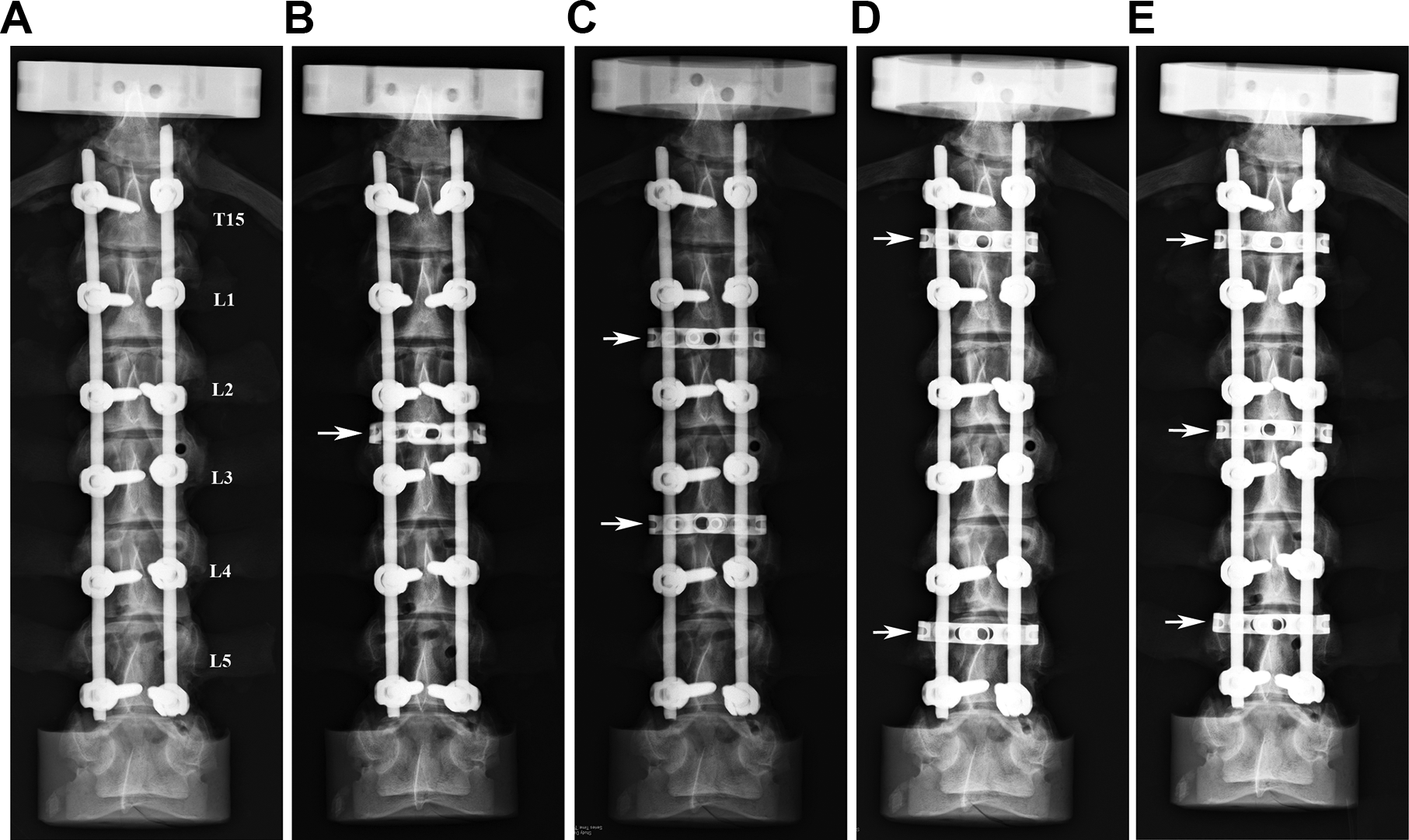
X-ray images showing 5 spinal constructs treated with different numbers and configurations of cross-links. All porcine spines underwent paired segmental screw implantations from T15-L5. (A) Group A: control group with no cross-links; (B) Group B: a single cross-link from L2-3; (C) Group C: 2 cross-links from L1-2 and L3-4; (D) Group D: 2 cross-links from T15-L1 and L4-L5, and (E) Group E: 3 cross-links from T15-L1, L2-3 and L4-L5. The arrow symbol indicates the position of the crosslink.
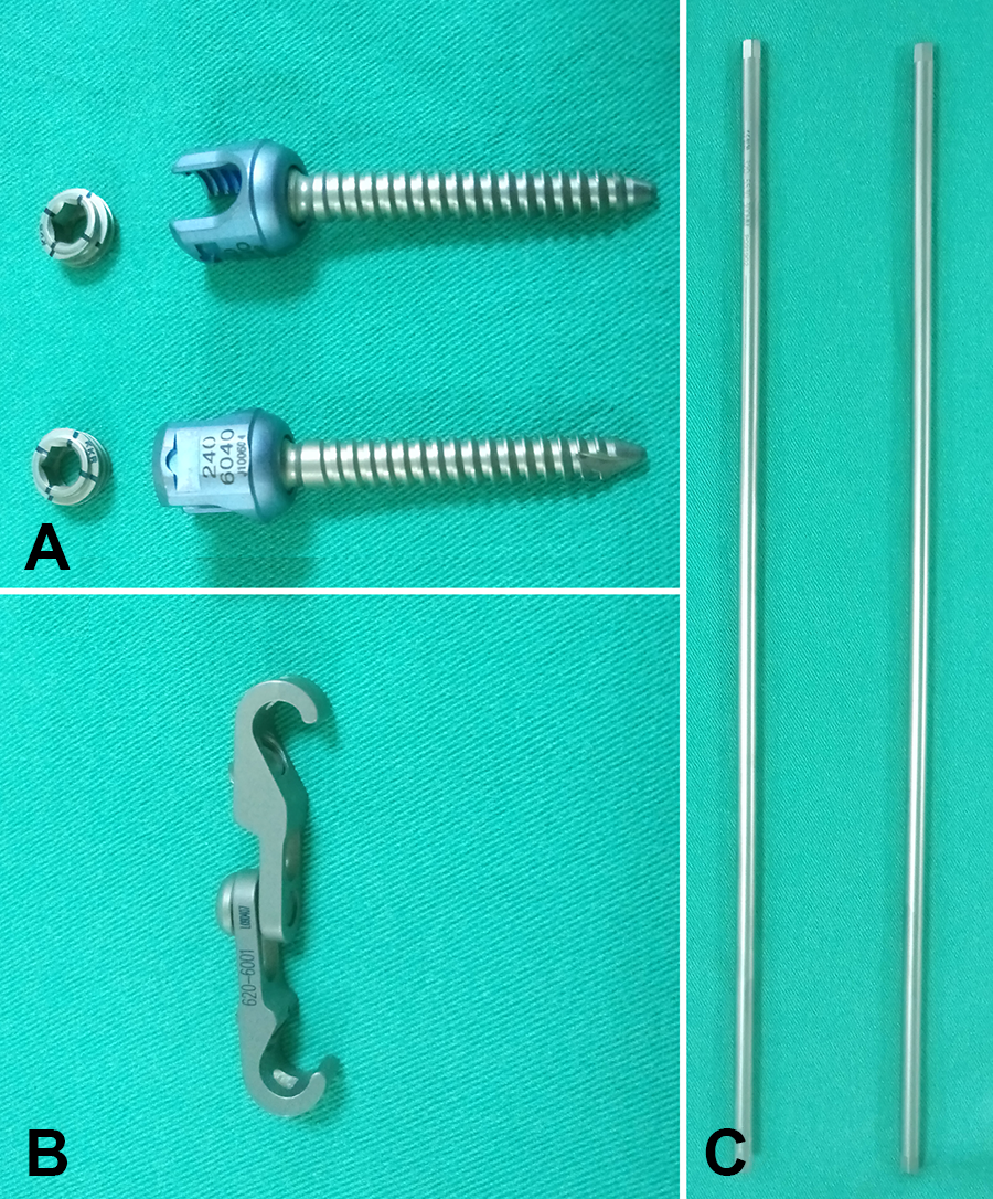
Photograph showing the fixation devices chosen and implanted into each pedicle of the vertebrae. (A) Poly-axial screws (diameter × length dimensions of 6.0 mm × 45 mm); (B) cross-link (6.0 mm width, 40-50 mm length); and (C) rod (diameter × length dimensions of 5.0 mm × 300 mm).
Prior to biomechanical testing, the bone integrity, screw depth/trajectory and spinal curves were assessed in both the sagittal and coronal planes using X-ray images. The specimens subsequently underwent mechanical tests when the appropriate screw trajectories, insertional depths and alignments were achieved; fractures or defects were not observed in the vertebrae in either the anterior-posterior or lateral view after instrumentation; and similar degrees of coronal and sagittal alignment were achieved among groups.
Biomechanical Testing
Based on our previous experiments using multiple segments of a porcine spine,14,15 the specimens were mounted for flexion, extension, lateral bending and axial rotation tests using a biaxial (axial and rotation) MTS testing machine (Bionix 858, MTS Corp., MN, USA). The most superior segment (T14) was embedded in an acrylic mixture (Buehler, Lake Bluff, IL, USA) and constrained by the upper clamp with an adjustable moment arm, whereas the most inferior segment (L6) was embedded in an acrylic mixture and constrained by the lower clamp. This experimental setup resulted in a compressive preload of 20 N due to the weight of the upper fixation acrylic mixture (Figure 1). Each specimen was nondestructively tested in 4 sequential modes: flexion, extension, lateral bending and torsion. In current study, a loading moment of 8,400 N-mm was chosen to avoid damaging the spinal column and to remain within the viscoelastic range.14,16,17 For the flexion, extension and lateral bending motions, an increasing moment magnitude of up to 8,400 N-mm was applied to the spine column generated through the axial movement of the MTS actuator, whereas the axial rotation motion was achieved by the axial rotation of the MTS actuator.14,16,17 For the flexion, extension and lateral bending motions, the clamp was designed with a pin that rotated horizontally across the upper plate, and the pin was perpendicular to the motion plane of the specimen. The horizontal pin and vertical motion path of the specimen resulted in a 3-D configuration that ensured that the specimen moved vertically as the spinal construct was flexed, extended or laterally bent. The position of the horizontal pin was adjusted to set the moment arm to 120 mm, and an increasing compressive force up to 70 N was applied to the horizontal pin across the upper plate. Therefore, the resultant applied moment was 8,400 N-mm. For the axial motion, however, the spine column was aligned with the MTS actuator, and an increasing rotation torque up to 8,400 N-mm was achieved by axial rotation of the MTS actuator. The experimental setups for the flexion, extension, lateral bending motions and axial rotation are shown in Figure 3.
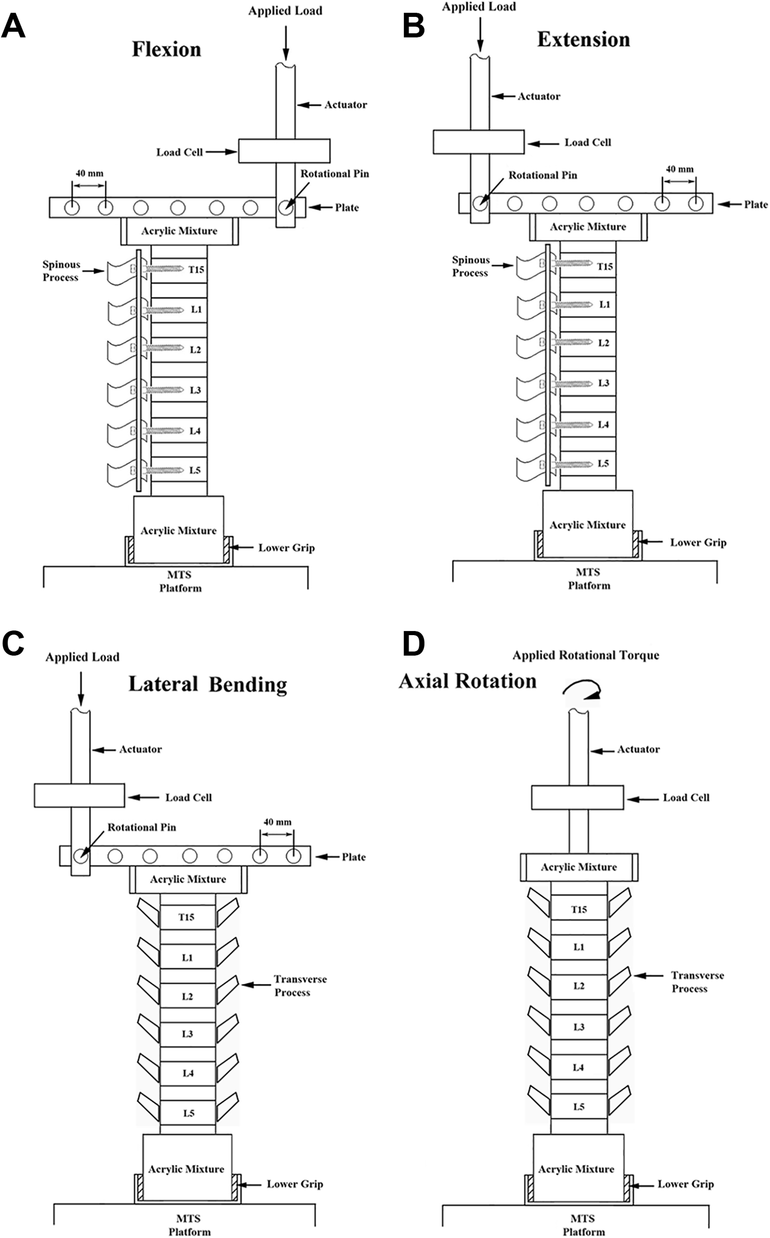
Diagram showing the experimental setup for (A) flexion; (B) extension; (C) lateral bending; and (D) axial rotation. The tests were performed on a biaxial (axial and rotation) MTS machine. A maximal 8,400 N-mm moment generated through the axial movement of the MTS actuator was applied to the spine specimen to achieve the flexion, extension and lateral bending motions, whereas axial rotation of the spine construct was achieved by the axial rotation of the MTS actuator.
During testing, the displacement or rotational angle data associated with the applied moment were recorded simultaneously using MTS Teststar II software (MTS Corp., MN, USA). The stiffness values in flexion, extension, lateral bending and axial rotation were defined as the slope of the straight line of applied moment (torque for axial rotation test) vs. displacement (rotational angle for axial rotation test) curves of spinal constructs at the latest phase of the test.
Statistical Analysis
All of the calculated spinal stiffness values were collected and are expressed as the mean ± standard deviation (SD). Statistical analyzes were performed using standard software (SPSS for Windows version 12.0, SPSS Inc., Chicago, IL, USA). ANOVA and post hoc least significant difference (LSD) tests were performed to evaluate the differences in spinal stiffness among groups. Statistical significance was indicated at P < 0.05.
Results
The average flexion, extension and lateral bending stiffnesses of the spinal constructs treated with 5 cross-link configurations (i.e., the “Group A: without cross-links,” “Group B: a single cross-link from L2-3,” “Group C: 2 cross-links from L1-2 and L3-4,” “Group D: 2 cross-links from T15-L1 and L4-5,” and “Group E: 3 cross-links from T15-L1, L2-3 and L4-5”) are shown in Figure 4. Significant differences were not observed among the groups in flexion, extension or lateral bending motions (P > 0.05) (Figure 4). In the axial rotational test, the representative applied torque versus rotational angle curves of spinal constructs treated with 5 cross-link configurations are shown in Figure 5A. For all 5 cross-link groups, a lower increasing rate of torque was found at the initial phase. This might be attributed to the inherent characteristic of neutral zone where little resistance is offered by the spinal column. In order to exclude such effect, the rotational stiffness was arbitrarily defined, for each group, as the slope of the straight line at the latest phase of the test. Based on the definition, the average rotational stiffnesses for groups A, B, C, D, and E were 2,511 ± 209, 2,679 ± 553, 2,502 ± 570, 3,615 ± 580, and 3,452 ± 495 N-mm/degree, respectively (Figure 5B). Significant differences in stiffness were not observed among groups A, B and C (P > 0.05), whereas significantly higher stiffness values were observed in groups D and E than in the other 3 groups (P < 0.05); however, the difference between groups D and E was not significant (P > 0.05) (Figure 5B).

Average flexion, extension and lateral bending stiffnesses of spinal constructs treated with various cross-link configurations. Significant differences were not observed among the groups in the flexion, extension and lateral bending motions (P > 0.05).
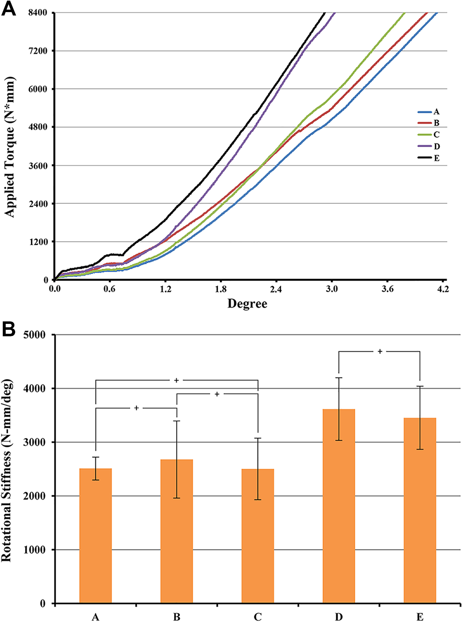
(A) The applied torque (N*mm) versus rotational angle (degree) curves of spinal constructs treated with 5 cross-link configurations for the axial rotational test and (B) a graphical comparison of the average rotational stiffness values of the 5 groups. Significant differences were not observed in the rotational stiffness among groups A, B and C (P > 0.05); the stiffnesses in groups D and E were significantly higher than those in the other 3 groups (P < 0.05); and the difference between groups D and E was not significant (P > 0.05). (Groups without significant differences are indicated by the “+” symbol.)
Discussion
The availability of fresh-frozen human cadavers is very limited; however, the porcine spine can be used as an alternative representative model because the vertebral body and spinal canal shapes and pedicle size are similar to those of humans.18,19 In our flexion bending test, significant differences were not observed among the groups, which is consistent with the results in a prior study. 12 The position and number of crosslinks were key factors in the flexion bending test, even in an unstable spine created using partial corpectomy with nonsegmental screws. 12 Previous researchers measured the impact of different numbers of cross-links on flexion, extension and lateral bending stiffnesses by using a calf spine from L2-5 and did not find any significant differences in any of the 3 bending tests. 20 The positions of the cross-links were unclear, thus hindering the results from being compared with those in our study. Hart et al. aimed to determine the effects of cross-links by comparing segmental screws with non-segmental screw constructs. 10 Different numbers of screws were used, which was a confounding factor and might have prevented the authors from reaching the goal of the original study. To the best of the authors’ knowledge, this is a well-established cadaveric biomechanical study on the roles of the position and number of cross-links in which the effects of confounding factors were reduced. The results showed that a significant difference occurred in the axial rotational stiffness when the 2 cross-links were fixed far away from the center. Finite element studies have also shown similar results. Cross-links have been shown to disperse the stress concentration, and rod breakage may be prevented when the cross-links are fixed at a distance from the weak point13,21 The authors demonstrated that the application of cross-links in long-segment fusion after spinal osteotomy increases axial torsional rigidity, and 2 sets of crosslinks were suggested, which is consistent with our results.10,13,21 The axial stiffness increased while the stiffness during the flexion, extension, and lateral bending tests did not significantly change when the appropriate number of cross-links were positioned properly. In an in vivo human model using 3-D MRI, each lumbar segment was axially rotated from a mean angle of 1.2° to 1.7°, and the trunk was rotated to 45°. 22 Structural rigidity in axial rotation of the spinal segment plays an important role in trunk rotation when considering spinal fusion. Cross-links act as mechanical couplings to secure the 2 spine rods together, and they not only share the loading force but also prevent motion between 2 horizontal constructs. From a physical perspective, the sagittal and coronal planes can be controlled by segmental screws with rigid rods; however, only fixed orthogonal devices prevent rod rotation.23,24
In a short-segment fusion study, Peltier et al. showed that constructs with one cross-link were 31% stiffer and those with 2 cross-links were 43% stiffer in torsion compared with constructs without cross-links. 9 In our results, axial stiffness was significantly higher in Group D than Group C, and similar results were observed between Groups D and E. Our results demonstrated that in a long-segment spinal construct, greater rotational rigidity may be achieved in a position-dependent manner by increasing the separation distance for the 2 cross-link configuration (Group C compared with Group D). However, the addition of an additional cross-link at the middle of the spinal construct (Group E) has little impact on torsion rigidity. This result implies that the position of the cross-link may play a more important role than the number of cross-links.
In clinical studies, Kulkarni et al. evaluated 208 instrumented spinal fusion cases with various etiologies and concluded that the use of cross-links in clinical practice may be avoidable. 25 In their study, the patients’ ages were not clearly reported, heterogeneous surgical methods were used, and both short- and long-segment fusion were performed, thus reducing the reliability of the results. Usmani et al. reviewed 256 cerebral palsy-related scoliosis patients treated with long posterior spinal screw fixation with or without cross-links and found no significant differences between groups in the correction achieved or correction maintained at the 2-year follow-up. 26 Dhawale et al. investigated the 2-year outcomes of crosslinks in 75 adolescent idiopathic scoliosis patients treated with long-segment posterior instrumented fusion and found that there were no differences in the correction achieved/maintenance, complication rates or clinical outcomes. 27
The discrepancy in the results of cross-links in long-segment spinal fixation from biomechanical and clinical studies may be attributed to several factors. First, different methods were used to analyze the data. In biomechanical studies, the results were evaluated by mechanical testing of the constructs after instrumentation. However, in the clinical studies, the results were evaluated by the rate of fusion and implant failure after at least 2 years of follow-up. Fusion involves complicated processes, including stability, bone quality, graft type/gap, aging, and decortication techniques,28-31 and cross-links play only a minor role in stability. Second, there are differences in spinal mobility between quadrupeds and humans. The long-level biomechanical studies mentioned above were performed in pigs or calves, which are quadrupeds.10,20 The axial rotational motion of the lumbar spine in the same loaded direction was found to be larger in humans than in porcine spines (P < 0.001). 32 Based on our data and the increased mobility of human spines relative to porcine spines, 32 it is reasonable to expect that cross-links would play a more important role in human cadaveric lumbar spines than in porcine spines. Third, in clinical long-segment fusion, instrumentation is always implanted from the thoracic spine to the lumbar spine,26,27 which means that the rotation of the whole construct can be limited by the limited axial rotation of the thoracic spine. 33 The presence of multiple confounding factors in clinical studies has prevented the role of cross-links from being established and used in clinical practice. Fourth, the porcine model has inherent limitations compared with humans, such as different geometries or density distributions of vertebrae, which might affect the generalizability of our results to human patients. 34 Testing from T15 to L5 only to eliminate rigid thoracic spine bias has also limited the applications of these models to clinical practice. Finally, a limited number of specimens might increase the variability of the data and reduce the statistical reliability.
Conclusions
In this in vitro biomechanical study, the stiffnesses in flexion, extension and lateral bending were not influenced by the number or position of the cross-links. However, the stiffness in axial rotation was significantly increased with 2 cross-links compared to one and positioned at the most cranial and caudal motion segments. Two cross-links individually placed proximal and distal from the center of the construct may be an optimal and efficient configuration to achieve biomechanical stability in non-rigid lumbar spines undergoing long-level fixation.
Footnotes
Declaration of Conflicting Interests
The author(s) declared no potential conflicts of interest with respect to the research, authorship, and/or publication of this article.
Funding
The author(s) disclosed receipt of the following financial support for the research, authorship, and/or publication of this article: The authors would like to thank the Ministry of Science and Technology of Taiwan for financial support (MOST 106-2221-E-182-018).