
Abstract
Study Design
A biomechanical study.
Objective
To evaluate the efficacy and feasibility of cement-augmented cortical bone trajectory (CBT) screw fixation.
Methods
Forty-nine CBT screws were inserted into lumbar vertebrae guided by three-dimensionally printed templates, and then injected with 0, .5, or 1.0 mL of polymethylmethacrylate. The screw placement accuracy, cement dispersion, and cement leakage rate were evaluated radiologically. Biomechanical tests were performed to measure the axial pull-out strength and torque value.
Results
Overall, 83.67% of the screws were inserted without pedicle perforation. In the 1.0 mL group, cement dispersed into the pedicle zone and formed a concentrated mass more often than in the .5 mL group, but not significantly more often (P > .05). The total cement leakage rate was 18.75%. Compared with the control group, the torque value was slightly higher in the .5 mL group (P = .735) and significantly higher in the 1.0 mL group (P = .026). However, there was no significant difference between the .5 and 1.0 mL groups (P = .431). The maximal pull-out force (Fmax) was increased by 52.85% and 72.73% in the .5 and 1.0 mL groups, respectively, compared with the control group (P < .05). However, the difference was not significant between the 2 cemented groups (P = .985).
Conclusions
Cement augmentation is a useful method for increasing CBT screw stability in osteoporotic spines. The cement injection volume is recommended to be 1 mL for each screw, and the cement should disperse into the vertebral body than the pedicle zones.
Introduction
The stability of pedicle screws is critical to the effect of spinal surgery. Studies have confirmed that the stability of pedicle screws is related to bone mineral density (BMD), and osteoporosis may lead to screw loosening, displacement, or even pulling out.1-4 Cement augmentation is a useful means to enhance pedicle screw holding power. One study found that it could increase pedicle screw pull-out strength by 147% to 300%. 5 However, the effect of cement augmentation on pedicle screws may be greatly compromised in severely osteoporotic spines. In one study, early loosening of cemented pedicle screws occurred when BMD was less than .6 g/cm2. 6 An increase of cement volume could enhance the effect of augmentation, but it may also cause a series of problems such as cement leakage, stress shielding effect, or accelerated degeneration of adjacent segments.7,8
The cortical bone trajectory (CBT) screw technique is another approach to increase spinal fixation stability. The CBT screw is inclined from caudal to cephalic in the sagittal plane and diverges from inward to outward in the horizontal plane. 9 The sufficient contact of inserted screws with cortical bone is responsible for higher screw holding power.9,10 Various studies showed that the biomechanical parameters of CBT screws were significantly higher than those of traditional pedicle screws.11-13 However, some contended that the biomechanical strength of CBT screws could not surpass that of traditional pedicle screws, especially in vertebral bodies with reduced bone stock. 14 Besides, the CBT screw loosening rate was raised with the increase of fixed spine segments. 15 Therefore, it is necessary to further increase the CBT screw fixation stability, especially in the face of the increasing number of osteoporosis patients.
To our knowledge, there has been little research on the application of cement augmentation to CBT screw placement. The purpose of this study was to evaluate the efficacy and feasibility of cement-augmented CBT screw fixation through osteoporotic cadaver biomechanics tests.
Materials and Methods
Specimen and Screw Preparation
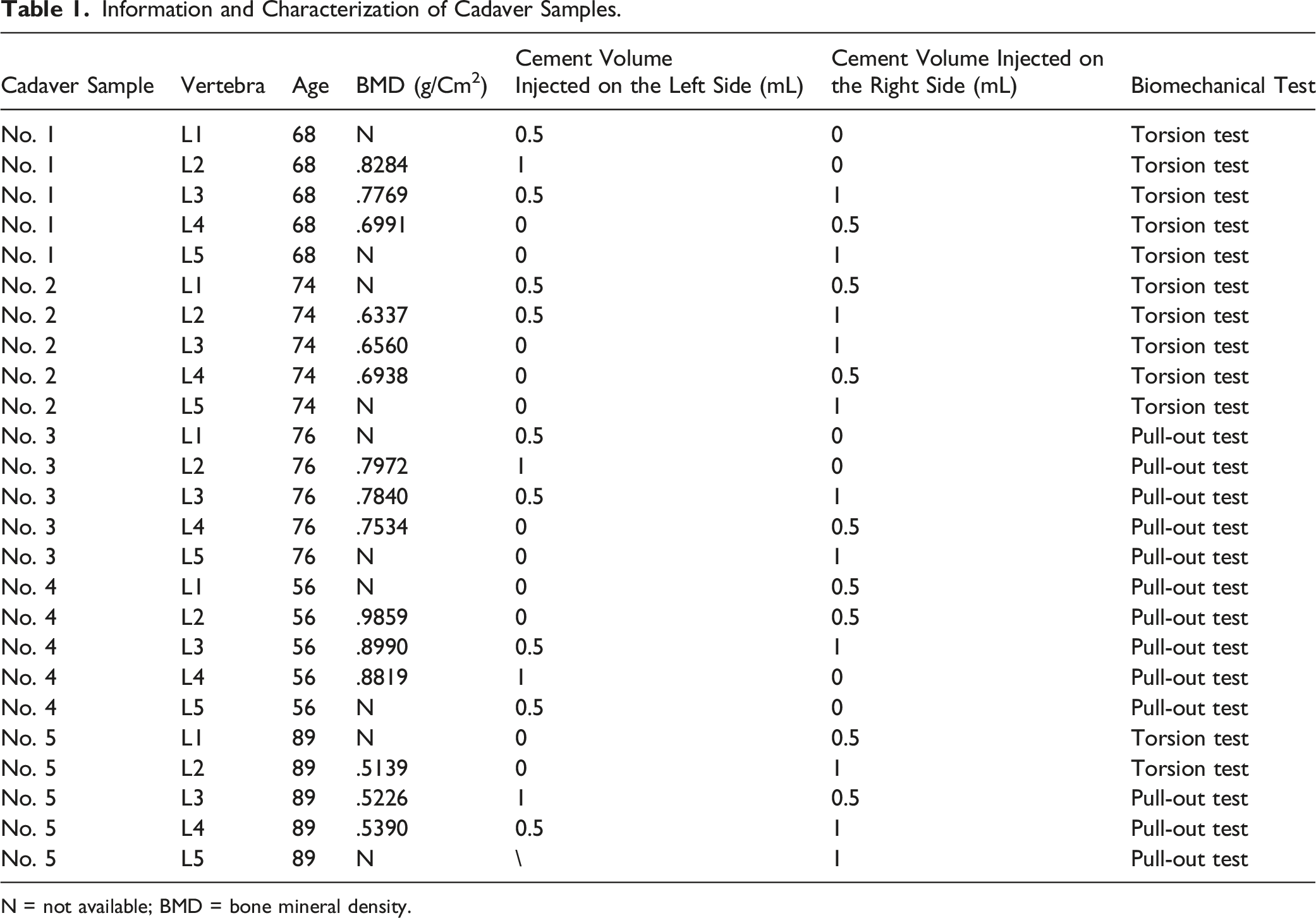
This cadaver study was approved by the Human Subjects Institutional Review Board of Peking University First Hospital (No. 2021-012), and the requirement of informed consent has been exempted by the ethics board. Five lumbar vertebrae (L1–L5) were harvested from fresh human cadavers ranging in age from 56 to 89 years; those with tumors, fractures, and deformities were excluded. The BMD of each specimen was obtained by a dual-energy X-ray absorptiometry scan to confirm the vertebrae were of compromised bone quality. Then, high-resolution CT scans were performed to collect radiological data needed for the simulation of screw insertion and the design of three-dimensionally (3-D) printed templates (Figure 1A). These specimens were stored at −20°C until operation and biomechanical testing. Forty-nine cement-injectable cannulated CBT screws (Premier, WGB1Z-7-01; Weigao Orthopaedic Device, Weihai, China) were employed, which were made of Ti6Al4V with an outer diameter of 5.5 mm and a length of 40 mm (Figure 1B). Design of three-dimensionally printed template and evaluation of the accuracy of CBT screw placements. (A) Schematic revealing that the design of three-dimensionally printed template according to the reconstruction of CT data to ensure that (1) the starting point is at the junction of the center of the superior articular facet and a line 1 mm inferior to the inferior border of the transverse process of the lumbar vertebra, (2) the screws are as parallel as possible and maintained an angle of 25–30° with the upper endplate of the vertebrae in the sagittal plane, (3) the screws have the same abduction angle in the coronal plane, and (4) the screw trajectory is designed to fully optimize cortical bone contact but not supposed to penetrate the vertebrae. (B) The cannulated CBT screw with 6 lateral 120° holes. (C) The planned screw and actual screw insertion direction in the sagittal and transverse planes.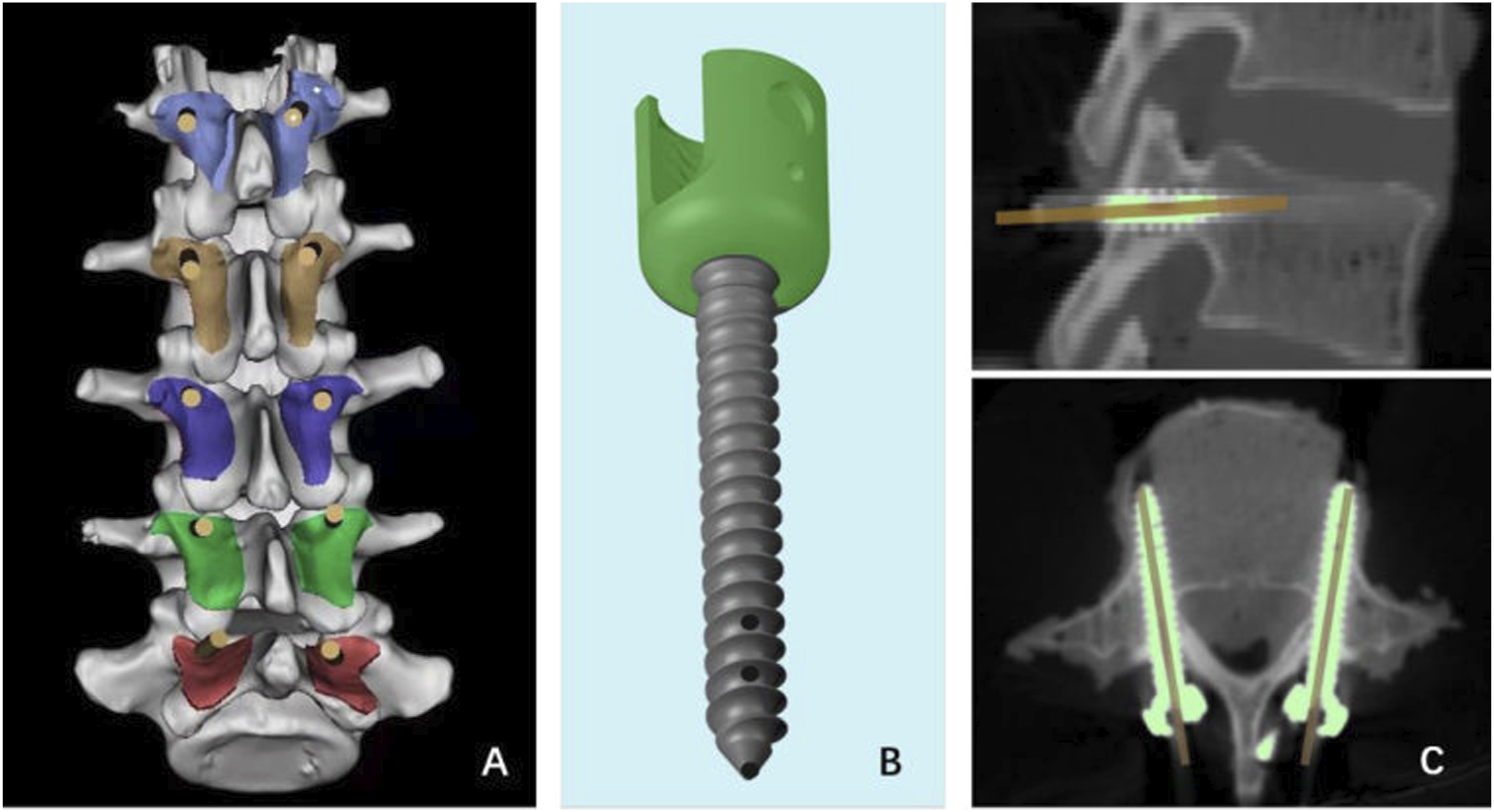
Screw Insertion and Cement Augmentation
CBT screw technique: The insertion position of CBT screws was selected at the intersection point of the mid-vertical line of the superior facet joint and the horizontal line 1 mm below the ipsilateral transverse process. The screw trajectory was inclined from caudal to cephalic in the sagittal plane, and diverges from inward to outward in the horizontal plane to insure sufficient contact of inserted screws with the dorsal cortex, the posterior medial and the anterior lateral pedicle walls, and the cambered surface of vertebral body. Then the screws were inserted into the specimens according to the prepared trajectory. To overcome the difficulty of the CBT technique in cadaver spines and ensure the accuracy and homogeneity of screw placement, the CBT screws were inserted with the guidance of the 3-D templates (The CBT screw insertion technique was shown in Figure 2A–F). Then some CBT screws were selected to be augmented with cement, that is, polymethylmethacrylate (PMMA). PMMA was mixed at a powder-to-liquid ratio of 2:1 and loaded into a customized syringe. Approximately 4.5 minutes after initial mixing, the PMMA reached a toothpaste-like consistency and was pushed through the cannula of the selected screws at the same speed (Figure 2G). The injected cement volumes in each screw are summarized in Table 1. The CBT screws were inserted into the lumbar vertebra under the guidance of 3-D printed templates. (A) The templates were positioned correctly closed contact with the posterior bony area after posterior soft tissue was removed from the cadaveric specimens, and an electric drill drove its bit of 2.5 mm in diameter into the vertebra along the direction of the template’s channel. (B) Insert the Kirschner wire in needle lumen. (C) A cannulated screw tap of 4.5 mm in outer diameter was used for tapping with guide of the Kirschner wire. (D) A tap as thick as the cannulated CBT screws was employed to expand the tapping hole along the prior direction. (E) A screw was inserted following the CBT trajectory. (F1) The specimen with 3-D printed templates; (F2) The specimen with screws placement. (G) The cement was injected through the cannula of the selected screws. Information and Characterization of Cadaver Samples. N = not available; BMD = bone mineral density.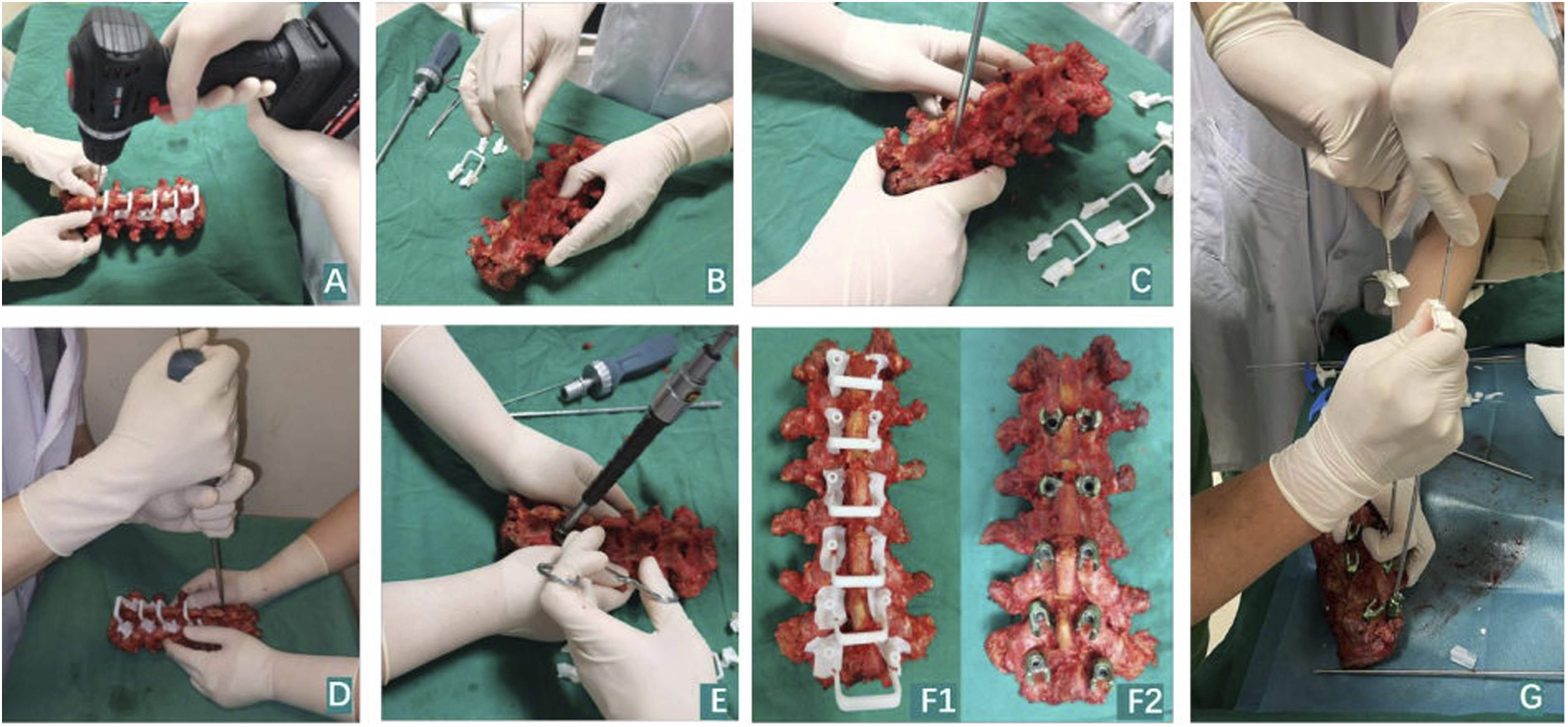
Radiological Evaluation
X-ray plain films and CT were performed to evaluate the safety and accuracy of screw position after screw insertions. The degree of perforation of the pedicle by the screw was classified into 4 grades using acceptance criteria: no perforation, grade A = 0–2 mm, grade B = 2–4 mm, and grade C ≥ 4 mm.
16
Deviations between the planned and actual screw positions were analyzed in terms of (1) the cranial angle of the trajectory in the sagittal plane and (2) the lateral angle of the trajectory in the transverse plane (Figure 1C). After cement augmentation, X-ray plain films and CT scans were performed again to evaluate the cement dispersion and cement leakage. The vertebral body was categorized into 4 zones on the axial view of each individual vertebra (Figure 3C), and the hardened cement masses were identified and categorized to the relevant zones. On the axial view of CT films, the morphology of the distributed cement was described as concentrated type (C) or scattered type (S) (Figure 3E). If it was difficult to identify the cement morphology type on the axial view of CT films, the 3-D CT reconstruction was used to reach a conclusion (Figure 3F). Radiological evaluation after augmentation with cement of different volumes. (A) A-P and lateral view of X-ray film of the specimen after inserting the screws and cement augmentation. (B) CT reconstruction of the specimen with screws cemented by PMMA. (C) Axial view of X-ray films of cement distribution zones: Zone 1 anterior third of the vertebral body; Zone 2 middle third of the vertebral body; Zone 3 posterior third of the vertebral body; Zone 4 pedicle area. (D) The result of cement location in the vertebral body. (E) The cement morphology in the vertebral body with axial view on CT scan. Left: concentrated type has the cement concentrated around the screw in a kind of round mass, Right: scattered type has the injected cement randomly scattered, spotted, or linearly distributed around the screw with some radiolucent space in the cement. (F) The cement morphology in the vertebral body in CT reconstruction. Yellow: concentrated type, Green: scattered type.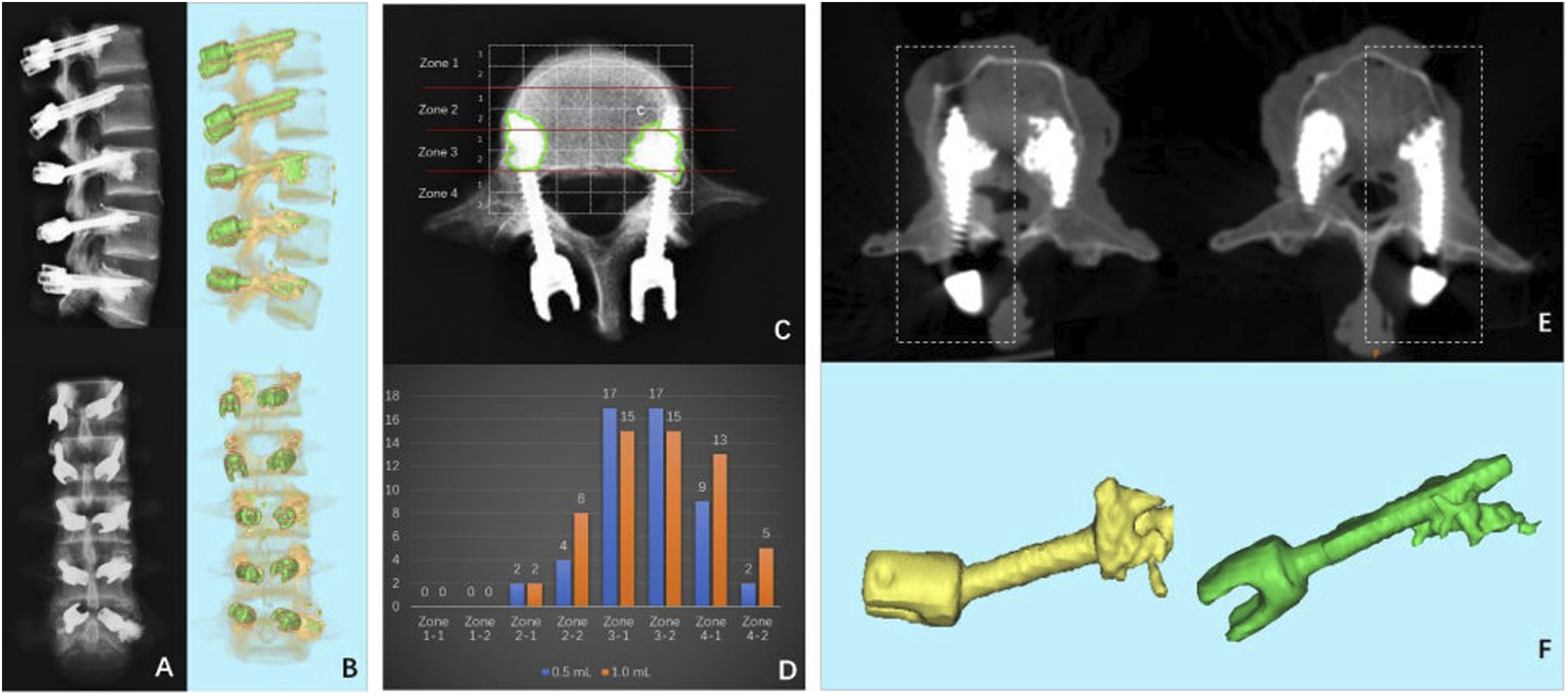
Biomechanical Tests
Some vertebrae were wrapped in denture base resins (Boer Chemical Co., Ltd., Shanghai, China) in a round custom-made mold, and screws were embedded leaving only the screw head exposed. A material testing machine (55 MT; Instron Universal Testing Machine, USA) was used to test maximum torque values. The head of the screw was connected to the load frame and rotated counterclockwise at a constant rate of .5°/s along the direction of the screw axis (Figure 4A). Testing continued until the torque value decreased significantly and the torque-angle curve was collected. Torque values and rotating degree data were collected in real time, and the maximal torque values were recorded as the load peaked and then sharply decreased with increasing degree (Figure 4B). Result of torsion test on CBT screws cemented with different volumes. (A) Schematic and photo showing the setup of torsion tests and horizontal alignment of screw in the vertebra. (B) Typical torque-angle curves of the torsion tests of canulated CBT screw with different volumes of PMMA. (C) Statistical results of the maximal torque of cannulated CBT screws with PMMA of 0, .5 and 1.0 mL.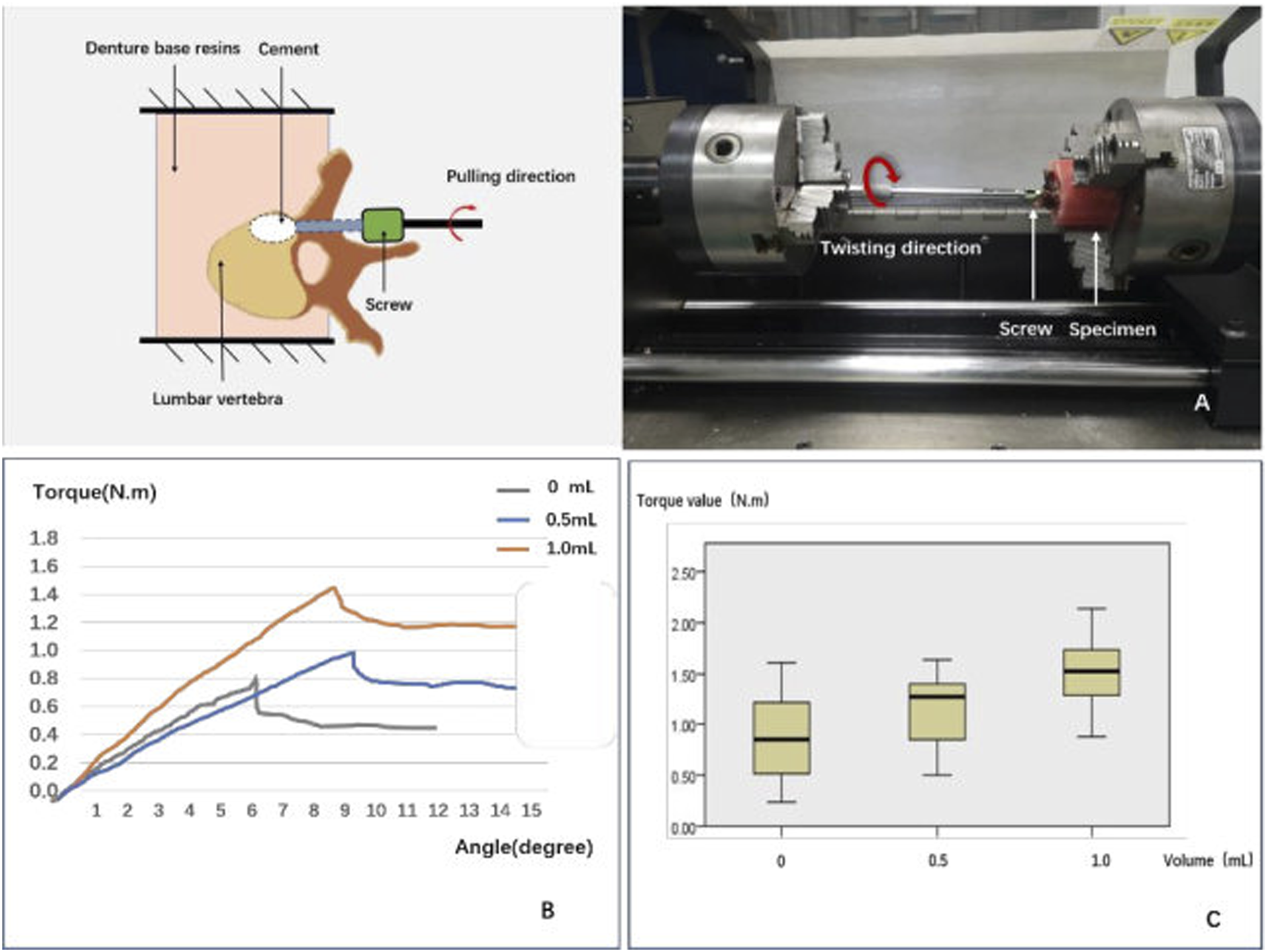
The other specimens were wrapped and sealed in denture base resins shaped by a square custom-made mold so that they could be mounted onto a special jig, which allowed for adjustment to ensure that each screw was pulled strictly along its long axis. Once the specimen was tightly secured, each screw was pulled at a constant speed of 5 mm/min until screw failure (Figure 5A), and the force-displacement curve was recorded. The maximum pull-out force (Fmax) was defined as the value at which the load peaked and then sharply decreased with increasing displacement (Figure 5B). Result of axial pull-out test on CBT screws cemented with different volumes. (A) Schematic and photo showing the setup of axial pull-out tests and vertical alignment of screw in the vertebra. (B) Typical force-displacement curves of the axial pull-out tests of canulated CBT screw with different volumes of PMMA. (C) Statistical results of the maximal axial pull-out strengths of cannulated CBT screws with PMMA of 0, .5 and 1.0 mL.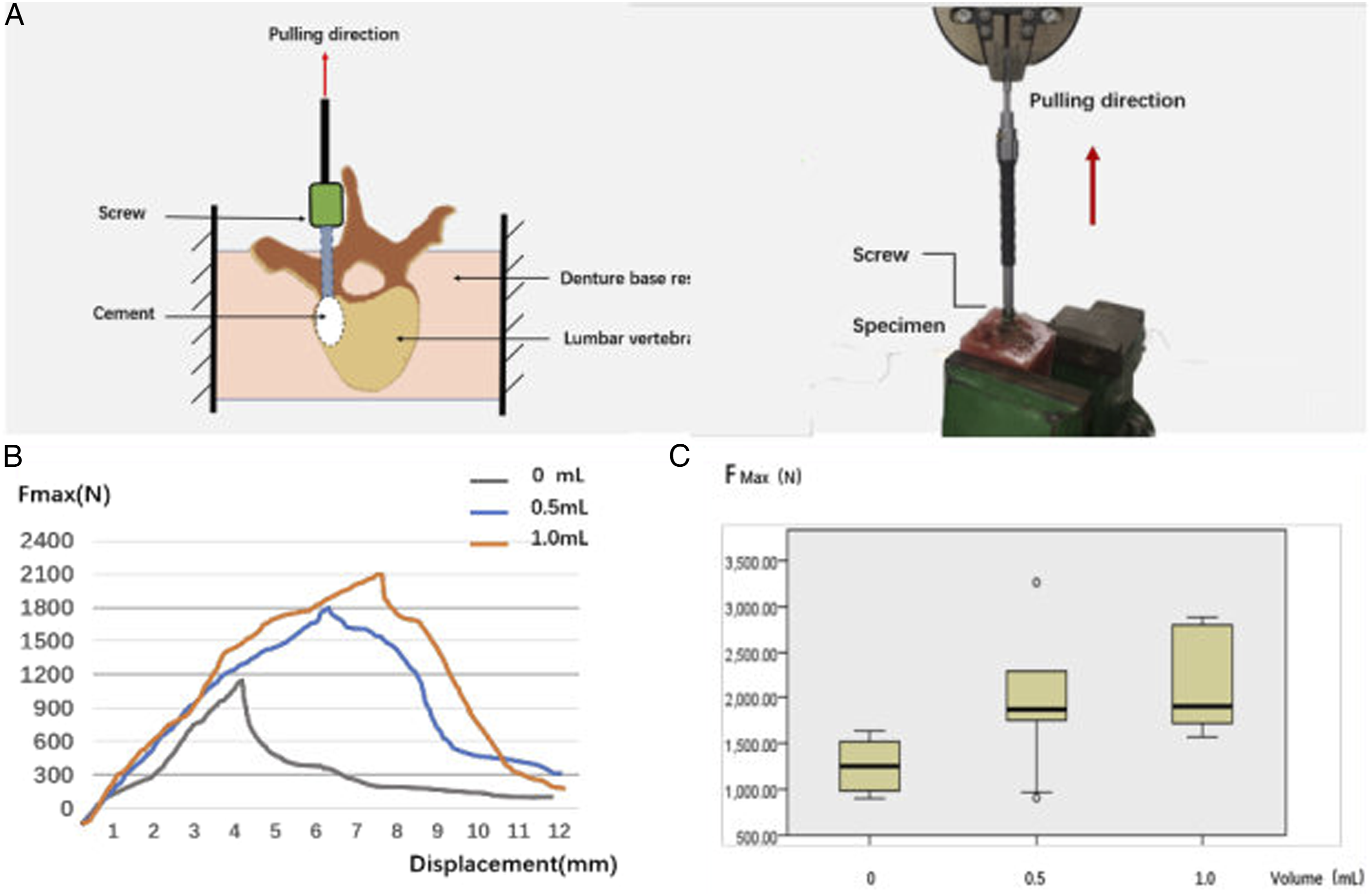
Statistical Analysis
Statistical analysis was performed with SPSS (version 23.0; SPSS Inc, Chicago, IL, USA). The data was expressed as mean ± standard deviation. Chi-square and Fisher’s exact tests were used for categorical variables. Kruskal–Wallis H tests were used to detect differences in continuous variables between different groups. Statistical significance was defined as P < .05 .
Results
Number of samples of groups with different cement volume and biomechanical testing values of each group.
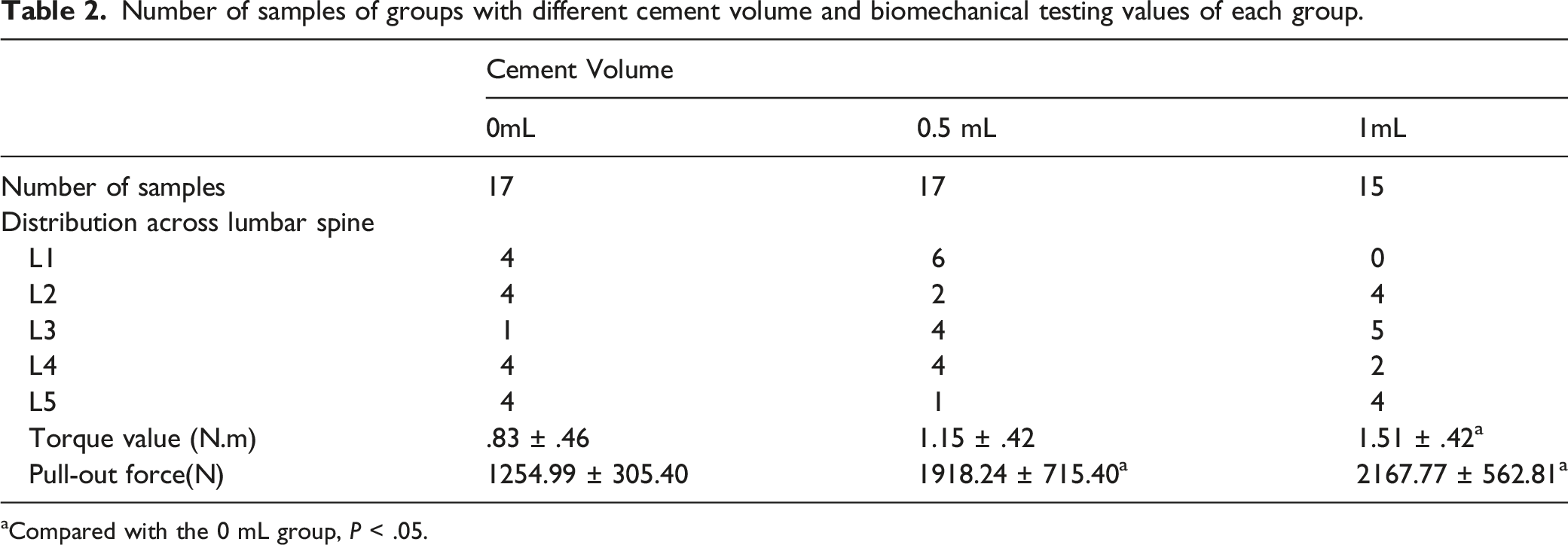
aCompared with the 0 mL group, P < .05.
Regarding screw placement safety, 41 screws (83.67%) were classified as no perforation, 5 screws (10.20%) as grade A perforation, 1 screw (2.04%) as grade B perforation, and 2 screws (4.08%) as grade C perforation. The potential critical breach (>2 mm perforation: grade B or C) rate was 6.12%. In the No. 2 specimen, the CT scan showed that 2 screws penetrated out of the medial border of the left pedicle of the L4 and L5 vertebral bodies (grade C), which were considered as false placements.
According to the screw insertion accuracy analysis, the mean angular deviations in the sagittal and transverse planes were 1.92 ± 1.15° and 1.70 ± .94°, respectively.
Six out of the 32 cemented screws (18.75%) experienced cement leakage, among which 2 cases leaked into paravertebral areas (from the 1.0 mL group), 1 case leaked into lateral pedicle areas (from the 1.0 mL group), and 3 cases leaked into canal areas (2 from the .5 mL group and one from the 1.0 mL group).
As for cement dispersion, Figure 3D shows the number of samples dispersed in each zone. It appeared that cement was more likely to disperse into the pedicle zone (zone 4–1, 4–2) in the 1.0 mL group than in the .5 mL group. However, the rate of dispersing into the pedicle zone was not significantly different between the .5 and 1.0 mL groups (1.0 mL: 86.7% vs .5 mL: 52.9%, P = .060). All of the aforementioned 3 cases that leaked into the spinal canal had cement located in the pedicle zones.
As for cement morphology, there were 16 screws with C type cement morphology and 16 screws with S type cement morphology. The cement in the 1.0 mL group tended to form a concentrated mass (C:S = 9:6), whereas the cement in the .5 mL group was inclined to shape a scattered cement cloud (C:S = 7:10), but the difference was not significant (P = .288).
The cemented CBT screws showed a significantly higher maximal torque value than those without cement (1.32 ± .45 vs .83 ± .46 N·m, P = .03). The torque value in the .5 mL group was slightly higher than that in the control group (1.15 ± .42 vs .83 ± .46 N·m, P = .735), and the torque value in the 1.0 mL group was significantly higher than that in the control group (1.51 ± .42 vs .83 ± .46 N·m, P = .026). Comparing the 2 cemented groups, the torque value in the 1.0 mL group was higher than that in the .5 mL group (1.51 ± .42 N·m vs 1.15 ± .42 N·m, P = .431), but the difference was not significant (Figure 4C).
The Fmax of cement-augmented CBT screws in the pull-out test was 2035.67 ± 641.06 N, which was significantly higher than that of non-augmented screws (1254.99 ± 305.40 N, P = .001). The Fmax was increased by 52.85% and 72.73% in the .5 mL and 1.0 groups, respectively, in comparison with the control group (P < .05). However, there was no difference in Fmax between the 1.0 mL and .5 mL groups (2167.77 ± 562.81 N vs 1918.24 ± 715.40 N, P = .985) (Figure 5C).
When comparing the biomechanical characteristics between the 2 different cement dispersion morphologies, it seemed that the C type had a higher biomechanical strength than the S type, but there was no statistical difference in torsion test (C: 1.59 ± .56 vs S: .91 ± .44 N·m, P = .069) or pull-out test (C: 2113.31 ± 750.65 vs S: 1981.31 ± 589.04, P = .089). When comparing the biomechanical characteristics between the 2 different cement distributions of pedicle zone and vertebral zone, the torque in the pedicle zone was higher than in the vertebral zone (1.38 ± .42 N·m vs .92 ± .57 N·m), though the difference was not significant (P = .069). As for pull-out strength, the Fmax values of the 2 groups were not significantly different (pedicle zone: 1894.96 ± 315.78 vs vertebral zone: 2193.97 ± 862.45, P = .354).
Discussion
The CBT technique has a steep learning curve, and the medial pedicle breach rate has been reported as 66.7% when screw placement is performed by surgeons with little experience in the CBT technique. 17 Even for experienced surgeons, the screw perforation incidence rate can reach up to 20% with the freehand method.18,19 In the in vitro experiments in this study, 3-D printed templates were used to ensure correct screw insertion. The results showed 83.67% of screws were completely inserted inside the pedicle without perforation, 93.88% were placed within 2 mm perforation, but 6.12% were unfortunately placed with >2 mm perforation. The 2 screw perforations classified as Grade C occurred in the No. 2 specimen, which was much smaller in size than the other specimens. Therefore, extra care should be taken when placing screws in spines of small size. As for the screw insertion accuracy, the results were similar to the study by Matsukawa et al., showing the mean angular deviations in the sagittal and transverse planes were 1.68 ± 1.24° and 1.27 ± .77°, respectively, 20 which indicated the 3-D printed templates facilitated accurate CBT screw placement.
The CBT screw technique could improve fixation stability through increased contact with cortical bone. Matsukawa et al. 13 showed the mean maximum insertional torques of CBT screws and traditional screws were 2.49 ± .99 N·m and 1.24 ± .54 N·m, respectively. Santoni et al. 21 found that CBT screws had a 30% greater pull-out load relative to traditional pedicle screws. In addition, Baluch et al 11 also demonstrated the superior resistance of CBT screws over traditional pedicle screws by cyclical loading and subsequent screw pull-out. Recently, Li et al. 12 reported that CBT screws outperformed traditional pedicle screws in terms of maximum insertional torque, axial pull-out strength, and fatigue loads, and CBT screws improved the axial pull-out strength by 38% compared to traditional pedicle screws. Cement augmentation has been regarded as an effective method to enhance screw anchorage in osteoporotic spines.7,22-24 However, few studies had compared the stability between CBT screws and cemented pedicle screws, and there was no evidence supporting the application of cement augmentation to the CBT technique. The present study focused on the improvement of CBT screws by cement augmentation. The results showed the mean maximal axial pull-out strength could reach up to 2035.67 N, which was increased by 62.2% compared with non-augmented screws. Some biomechanical studies showed the maximal axial pull-out strength of traditional pedicle screws ranged between 380 N and 491 N in osteoporotic cadaveric spines23,25-26. The effect of cement augmentation in traditional pedicle screws has been already proved, Several previous studies reported the maximal axial pull-out strength of PMMA-augmented traditional pedicle screws ranged between 501 N and 1337 N in cadaveric spines.23,27,28 The mean axial pull-out force of non-augmented CBT screws in our study was 1254.99 N, which falls near the end of this range, suggesting the CBT screws could compete with cement-augmented traditional pedicle screws. Compared with the mean pull-out strength reported historically, the mean force value in our study was about 200N lower than that reported by Matsukawa et al. 10 of which the CBT screw size was same as ours. The potential reason was that the specimens in our study were characteristic of more severely compromised bone quality. The measured force of cemented CBT screws in the present study was much higher than the CBT screws without cement, indicating the cement augmentation of CBT screws worked well. Indeed, the removal torsion value was increased by 59.4% after cement augmentation, which also demonstrated the screw surface strength was greatly improved.
To identify the suitable cement volume, .5 mL and 1 mL volumes of PMMA were employed. The results suggested both volumes were able to significantly improve screw pull-out strength, and no statistically significant difference in pull-out strength was observed between the .5 mL and 1 mL groups, meaning the volume increment of .5 mL did not make a significant difference. This phenomenon is similar to the cement augmentation of traditional pedicle screws in a biomechanical study by Liu et al, 29 who found there was no significant change in pull-out strength when the PMMA increased from 1.0 to 1.5 mL or from 1.5 to 2.0 mL, but there was a significant stability increase when PMMA increased from 1.0 to 2.0 mL. In terms of maximum torque values, the .5 mL group did not have a significant change over the control group, but the 1 mL group did, suggesting the torque relies more on there being a sufficient cement volume dispersed around the screws.
It has been confirmed that traditional pedicle screws with cement close to pedicle areas have higher pull-out strength. 30 However, this phenomenon was not found in cemented CBT screws, suggesting the potential for improving the pull-out strength of cemented CBT screws lies in the cancellous bone in the vertebral body. Because the torsion test reflects the surface strength and the separation occurs in the screw-cement/cortical bone surface, 31 the torque value was higher in the pedicle zone than in the vertebral zone, although the difference was not significant. Another factor impacting the cemented screw stability is the cement morphology. 32 However, there was no difference in pull-out strength or torque value between the C type and S type cement morphologies of the cement-augmented CBT screws, which could be because the cement volume used for CBT screw augmentation was so small that the role of cement morphology was negligible.
In our study, the cement leakage rate was 18.75%. All 3 cases that leaked into the canal belonged to the pedicle zone, which was consistent with the results of previous studies on cement-augmented pedicle screws that the closer the cement mass is to the pedicle, the higher the risk of cement leaking into the spinal canal.8,33 The 1.0 mL group did not show a higher cement leakage rate into the spinal canal than the .5 mL group, suggesting an injected cement volume within 1.0 mL was safe as long as the cement mass location was suitable.
When we meet patients with osteoporosis who need CBT screw fixation in clinical practice, if the patients have risk factors of screw loosening and pulling out such as long segment fixation, low bone density, or high body mass index, etc., we can try using bone cement to strengthen the screw anchorage. However, there are still some aspects needed to be further research: how to improve the design of the screw holes to form better dispersion of bone cement in the vertebral body, how to reduce the cement leakage, and how to find a new augmentation material with better dispersion pattern and biodegradability.
Our study had limitations. Firstly, the number of donated cadaveric spines used in this biomechanical study are limited, which might be influenced by the culture beliefs in our country. Secondly, clinical evaluation of vertebral BMD by a dual-energy X-ray absorptiometry scan usually chooses the L2-4 segments as region of interest, living the BMD values of L1 and L5 not available. However, the reason why we measure BMD is to confirm the aging specimens are of compromised bone stock overall, so we can still get some enlightenments from this biomechanical study. Future research is going to designed to illuminate the effect of bone loss severity degree on the cement-augmented CBT screws when the donated specimens are suitable. Additionally, the screws used in this study are not specifically designed for cement augmentation applied to CBT technique. Our team intends to develop a newly designed CBT screws which would control the direction of cement dispersion to improve this application.
Conclusion
Cement augmentation is a useful method to raise CBT screw stability in osteoporotic spines. We recommend 1 mL as the suitable volume of cement injection for each CBT screw, and the cement should disperse into the vertebral body rather than the pedicle zones.
Footnotes
Declaration of Conflicting Interests
The author(s) declared no potential conflicts of interest with respect to the research, authorship, and/or publication of this article.
Funding
The author(s) disclosed receipt of the following financial support for the research, authorship, and/or publication of this article: This study is supported by Natural Science Foundation of Beijing, China (7212117) and National Natural Science Foundation of China (82025025).