
Abstract
Study Design:
Clinical case series describing a novel surgical technique.
Objective:
Stabilization across the cervicothoracic junction (CTJ) poses technical difficulties which make this procedure challenging. The transition from cervical lordosis to thoracic kyphosis and the orientation of the lateral masses of the cervical spine compared with the pedicles of the thoracic spine create the need to accommodate for 2 planes of alignment when placing instrumentation. A novel surgical technique for instrumentation across the cervicothoracic junction is described.
Methods:
The use of cortical bone trajectory (CBT) technique for pedicle fixation in the upper thoracic spine is described in combination with cervical lateral mass or pedicle screws. The application in our first 12 patients for stabilization across the CTJ is described. Two case presentations illustrate the technique.
Results:
All the patients had rod screw constructs without the need to skip levels, there was no requirement for transverse connectors and only 1 plane of contouring was required.
Conclusions:
The use of CBT technique has not been described for the upper thoracic spine. This technique avoids many technical problems associated with posterior instrumentation of the CTJ. The facility of their use in this application arises from the similar coronal plane entry points as the cervical lateral mass screws compared with the more lateral starting point of traditional thoracic pedicle screws. The technique has clinical equipoise to traditional thoracic pedicle screw insertion but with the benefits of an easier ability to perform the instrumentation and saving levels of fusion.
Introduction
The cervicothoracic junction (CTJ) is a complex anatomical site due to the transition from the lordotic flexible cervical spine to the kyphotic rigid thoracic spine. It is common practice to span the CTJ as stopping a construct at the junctional level may cause adjacent level instability. 1 –3 Posterior instrumentation of the CTJ is often preferable to anterior surgery as this avoids a potentially difficult anterior approach to this area which contains vital vascular and neural structures 4,5 and is biomechanically superior to anterior plating in terms of rigidity and stiffness. 6 –8 Posterior surgery is also indicated for multilevel injuries.
Several techniques for CTJ posterior instrumentation have been developed. Screw-rod systems have become the standard of care as they are biomechanically superior and the advent of polyaxial screws has further facilitated this technique. Screw-rod systems can be used with laminectomy, which is often required to manage traumatic, neoplastic and degenerative pathologies. 8 –10
Cortical bone trajectory (CBT) for screw placement is a recent technique and has been mostly described in the lumbar spine. This was initially popularized by Santoni et al 11 in 2009. CBT thoracic pedicle screw technique was described by Matsukawa et al 12 in 2017.
The purpose of this study was to describe a novel technique for posterior instrumentation of the CTJ using lateral mass screws for the subaxial cervical spine and CBT screws for the proximal thoracic spine. The benefits of using CBT screws compared with the standard pedicle screw in the thoracic spine avoids many technical problems in posterior screw-rod instrumentation such as the need to skip levels and multiplanar rod contouring. This is the first report of using CBT screws for instrumentation in the upper thoracic spine and for instrumentation of the CTJ.
Methods
This study is a prospectively collected cohort of 12 patients (8 males and 4 females) who underwent posterior CTJ instrumentation from May 2016 to March 2018 using the cortical bone trajectory technique for thoracic pedicle fixation. The pathologies for the 12 patients included 7 cervical fractures, 2 patients who were ASIA (American Spinal Injury Association) A, 3 patients were ASIA C, and 2 ASIA D. Three patients had cervical spondylotic myelopathy and 2 patients had a diagnosis of cancer. The mean age was 57 years. All patients underwent perioperative plain radiograph imaging, computed tomography (CT) scan, and/or magnetic resonance imaging (MRI). The demographic data, pathologies, and operative details are illustrated in Table 1. The study was approved by the hospital’s institutional review board.
Cohort of Patients Undergoing Cortical Bone Trajectory Screws at the Cervicothoracic Junction.
Surgical Technique
All the operations were performed by the same surgeon under general anesthesia in the prone position. The neck was maintained in a neutral position using Mayfield skull clamp or Mayfield horseshoe headrest. After standard sterile preparation and draping, long-acting local anesthetic with 0.025% epinephrine was injected along the line of the incision subcutaneously to decrease blood loss. A conventional posterior approach was used to expose the lamina and lateral masses of the cervical spine and the lamina and facet joint of the proximal thoracic spine as indicated for the levels of instrumentation. Confirmational lateral X-ray was obtained as needed.
In the subaxial cervical spine, the dissection extended to the lateral border of the lateral masses on both sides. Lateral mass poly axial screws (Oasys Stryker or Virage Zimmer Biomet) were inserted using standard Magerl technique. 13 A high-speed burr was used to create the entry point, stepwise drilling and using a sound probe was performed to determine depth and to obtain bicortical purchase.
In the proximal thoracic spine, the dissection extended laterally to expose lamina and facet joint. The entry point for the CBT screws was modified from that described by Matsukawa et al. 12 The intersection of the lateral two-thirds of the superior articular process and the inferior border of the transverse process was used but then biased medially to line up with the cervical spine lateral mass starting points. The cortical bone trajectory is in a lateral trajectory from 0° to 10° in the coronal plan and a cranially angulated trajectory approximately 30° in the sagittal plan. The CBT now allows for both the heads of the cervical and the thoracic screws to be aligned in the coronal plane. The sagittal plane direction of the CBT screw moves the head of the screw more caudally and eliminates abutment of the C7 and T1 heads. This allows easier connection with a rod between C7 and T1.
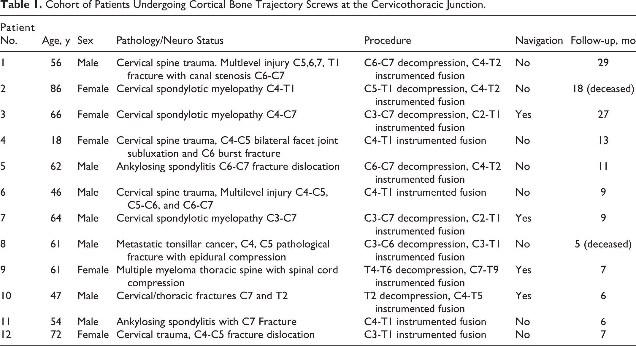
High-speed burr was used to create the entry point. A step drill was used to create the path for the CBT screw (Figure 1). Stepwise drilling followed by sequential palpation of the tract with a sound probe ensured we were contained within bone in all 4 walls and drilling was stopped once there was transition from a hard floor to soft. The neuroforamen of the named pedicle is at risk if cranial inclination is not sufficient. A screw length of less than 15 mm would raise concern of foraminal breach. As part of the routine technique of placing all pedicle screws, the stability of each screw is assessed by tactile feedback insertional torque judgment.
Navigation screenshot for intraoperative planning of right cortical bone trajectory (CBT) screw insertion in the proximal thoracic spine. The orientation of the CBT screw is demonstrated with a caudal to cranial inclination in the sagittal plane and a slight lateral inclination in the coronal plane.
Intraoperative 3-dimensional navigation was used in 4 cases to insert the CBT screws (Stryker Nav 3). A reference clamp was attached to the spinous process of C7. Point-to-point matching and surface matching on the T1 vertebra was performed. CBT screw orientation and length were determined directly with confirmation of screw placement by using the sound probe.
After screw placement, laminectomy was performed as indicated. Rods were then contoured to accommodate the sagittal alignment and attached to the screws. Correction of deformity with compression or distraction was performed as indicated for the specific case. There was no coronal rod contouring required, there was no need to skip any levels to accommodate the rod insertion, there was no requirement for lateral connectors. Bone grafting with local bone was morcelized and packed into the facet joints after burring of the articular cartilage in order to obtain fusion.
Following routine closure, drains were not routinely used, and postoperative cervical collars were not routinely applied. All patients had postoperative CT scans to evaluate hardware position.
Results
The follow-up period was 5 to 29 months with a mean of 12 months. Two patients were deceased at 5 and 18 months. There were no screw-related complications, no neurological injuries, no hardware failures, and no revisions. All cases achieved immediate stability and were mobilized as tolerated immediately following surgery. All achieved clinical fusion. Insertional torque assessment at time of CBT screw insertion was uniformly strong for all T1 screws. T1 screw lengths were 16 to 26 mm.
Case 1
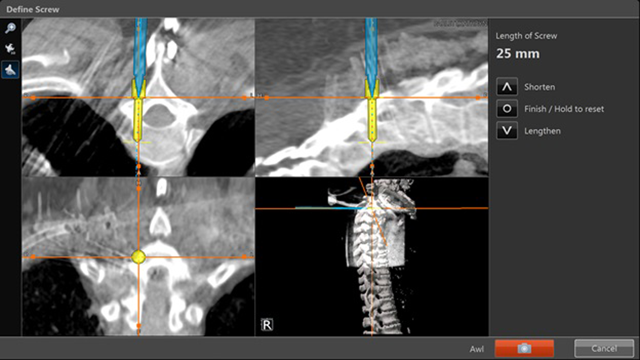
An 18-year-old female patient presented after an unwitnessed fall from a 25 feet height from which she suffered multilevel cervical spine fracture with C6 teardrop body fracture and lamina/facet injuries at C4-5, C5-6, C6-7 and complete spinal cord injury. Posterior instrumentation and fusion were done from C4-T1 using lateral mass screws for the cervical spine and CBT for T1 (Figure 2).
(a) Preoperative sagittal computed tomography (CT) scan. (b) Preoperative axial CT scan. Postoperative anteroposterior radiograph. (d) Postoperative lateral radiograph. (e) Postoperative axial computed tomography (CT) scan of the left T1 cortical bone trajectory (CBT) screw.
Case 2
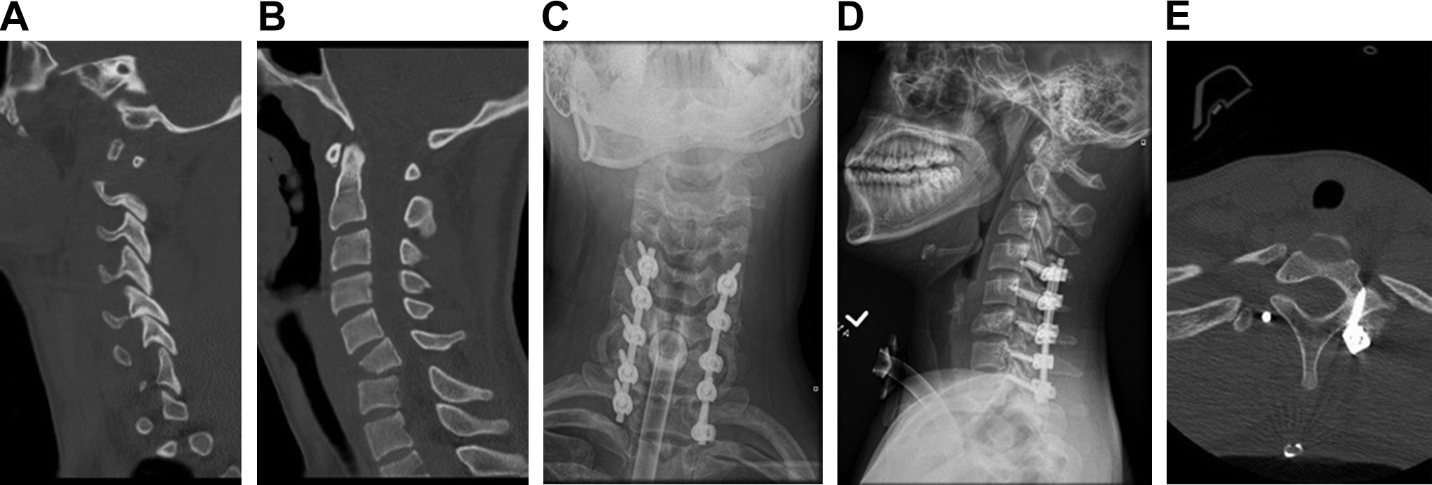
A 64-year-old male presented with symptoms of cervical spondylotic myelopathy. Preoperative MRI revealed multilevel degenerative disc disease and severe canal stenosis with increased cord signal. Posterior decompression from C3-C7 and instrumented fusion from C2-T1 using CBT screw was performed (Figure 3). At 9 months, he had improvement in gait but had continued hand weakness and decreased dexterity. His X-rays showed excellent alignment and fusion. A follow-up MRI showed good decompression with myelomalacia of the spinal cord.
Preoperative sagittal magnetic resonance imaging (MRI) demonstrating severe cervical stenosis. There is increased signal within the spinal cord. (b) Postoperative anteroposterior radiograph. (c) Postoperative sagittal computed tomography (CT) scan demonstrating position of the left T1 cortical bone trajectory (CBT) screw. (d) MRI scan at 9 months postoperatively showing good decompression of the spinal cord with myelomalacia, which can account for the continued myelo/radicular signs and symptoms.
Discussion
Anterior and posterior approaches can be used for stabilization of the CTJ. Anterior fixation is less biomechanically stable and if an anterior approach is required for decompression, a posterior instrumentation is often also necessary. 14 –17 The CTJ has complex biomechanical and anatomical properties that make instrumentation across this area challenging. These include transition from the mobile lordotic cervical spine to rigid kyphotic thoracic spine. 15,18 Additionally, there is variation in the size of vertebral bodies between these 2 anatomical sites. 16 The posterior screw-rod system has the advantage of immediate rigid internal fixation, high rate of fusion, deformity correction and the ability to perform compression and distraction.
Posterior subaxial cervical spine screws are most commonly placed in the lateral mass but can also be placed in the pedicle. Although transpedicular screws are superior to other techniques in terms of strength and stability it is technically more difficult and has higher risk to the spinal cord due to small pedicles and the medial angulation. 19 Navigation can facilitate the placement of cervical pedicle screws. 20
The lateral mass screw avoids the technical difficulty of transpedicular screw insertion. The biomechanical strength of lateral mass screws is inferior to pedicle screw, and the C7 lateral mass is often small in comparison with the more proximal levels. 10 Lateral mass screws require a medial to lateral inclination in the coronal plane, which has less risk of injury to the spinal cord. 13,18
Traditional thoracic pedicle screw fixation has been well described. 21 Placement of thoracic pedicle screws entails a lateral to medial inclination. The T1 pedicle and to a lesser extent the T2 pedicle has a more medial inclination compared with the rest of the thoracic spine. The average T1 medial angulation is 31.65° and 23.35° for T2. 22 Pedicle breaches in the upper thoracic spine has been reported to be 29% using an open technique (laminoforamintomy) and 18% with fluoroscopy. 23 The use of intraoperative navigation has improved accuracy. 24
The directionality of the traditional thoracic pedicle screw (lateral to medial) is opposite from the laterally directed lateral mass screws in the cervical spine This creates difficulty connecting the subaxial cervical spine screws to the proximal thoracic screws. The traditional thoracic pedicle screw is also oriented from a cranial to caudal direction. This brings the heads of the adjacent C7 and T1 screws close together. Skipping a spinal level, either C7 or T1 is often required to accommodate the rod. The requirement of biplanar rod contouring, sagittal to accommodate the cervical lordosis/thoracic kyphosis, and coronal to accommodate the more medial cervical lateral mass screws with the more lateral thoracic pedicle screws, adds further complexity and time (Figure 4). Offset connectors or omitting fixation at an intercalary level may be required. Both these options decrease the biomechanical stability of the overall construct (Figure 5). 25 The fusion construct may have to be lengthened to obtain enough stable points of fixation. Multiple attempts at rod bending to fit the screws can weaken the mechanical properties of the rod, which can further lead to decrease in the fatigue and yield strength, potentially leading to instrumentation failure. 26,27
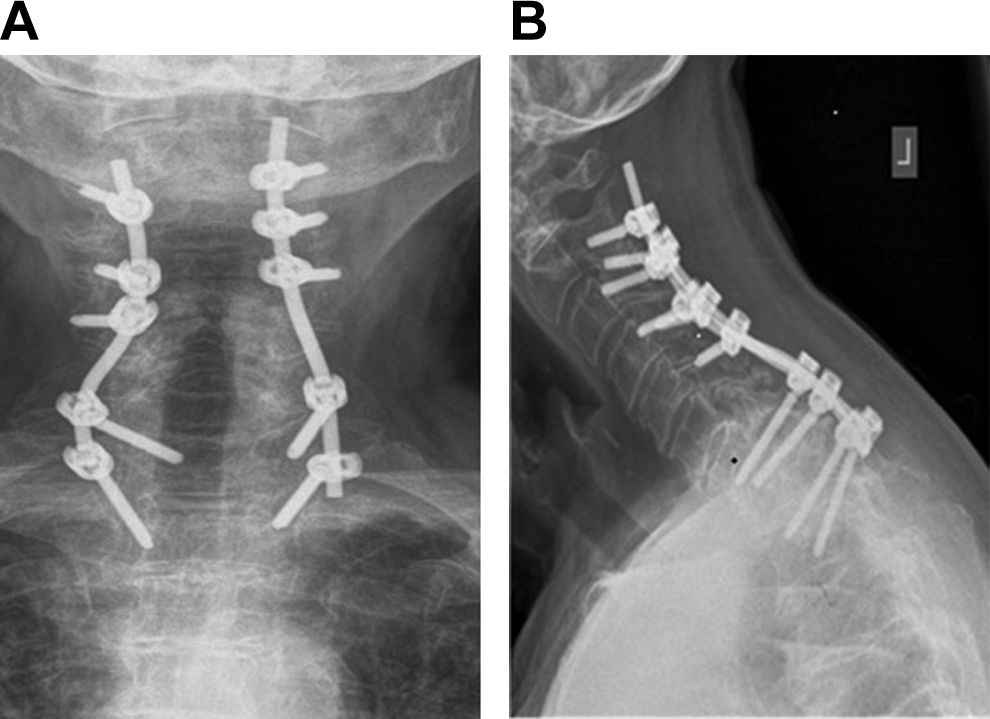
(a) Postoperative anteroposterior (AP) radiograph following stabilization for C5-C6 facet fracture subluxations. Complex coronal plane contouring of the rod was required to accommodate the connection between the cervical lateral mass screws and conventional thoracic pedicle screws. (b) Sagittal plane contouring is required to accommodate the normal cervical lordosis and thoracic kyphosis.
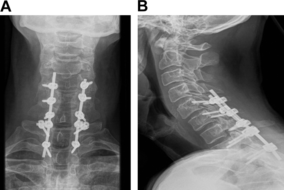
(a) Postoperative anteroposterior (AP) radiograph following stabilization for C7/T1 flexion injury demonstrating offset connectors were required to connect the T1 screws to the rod. The opposite coronal plane orientations of the C7 and T1 screws are well demonstrated. (b) Normal sagittal plane contouring for the cervical lordosis and thoracic kyphosis.
Our entry point for the CBT screws in the proximal thoracic spine has a similar coronal entry point as the lateral mass screws in the subaxial cervical spine. 12 There has been no cadaveric study that defines the optimal entry point in the upper thoracic spine. We chose our entry point based on the published work on lower thoracic spine, 12 but used a slightly more medial landmark such that it aligns with the C7 lateral mass screw. The orientation is then idealized laterally and cranially, initially defined by the use of navigation. Once the surgeon is familiar with the trajectory, the screws can be placed freehand with a step drill technique drilling at 2-mm increments.
There is a safe zone for screw placement directed above the exiting nerve root foramen and terminating in the subchondral bone of the endplate. The screw length depends on where in this zone the trajectory is. The CBT screws are shorter than the traditional pedicle screw; however, the biomechanical strength has been shown to be superior than traditional screws in the lumbar spine. 11 There has been no direct biomechanical study in the upper thoracic spine but with idealized placement, the surgeon’s tactile sense of insertional torque will provide good feedback on the stability of the screw. However, a screw that is too short may not be as stable as an idealized CBT screw or even a traditional pedicle screw. It is for this reason that a screw length of less than 15 mm would raise concern of foraminal breach and often was found to have suboptimal feedback insertional torque. Overangulation in the sagittal plane, which avoids the neuroforamen, will also result in a shorter screw. Navigation is beneficial to obtain the ideal screw placement with the longest screw possible that ends in the subchondral bone of the superior endplate of the vertebra.
We have not found a need to perform a hemilaminectomy for CBT placement in the upper thoracic spine. The entry point is well visualized, the lateral extent of the spinal cord is noted by palpating the medial edge of the facet joint. The coronal plane direction is away from the spinal cord, which in our opinion makes this a safer screw trajectory than the traditional thoracic pedicle screw.
The limitation of the present study is that there is no biomechanical data for the use of these screws in the upper thoracic spine. This does exist for CBT screws in the lower thoracic and the lumbar spine. It is our experience using the CBT screw technique routinely for many thoracic spine and lumbar spine instrumentations that the insertional torque is higher for all cases compared to the traditional screw orientation. It is this finding that has popularized this technique for osteoporosis, 11 which in our opinion makes the CBT technique valuable for all cases and not be limited to osteoporosis. For our technique at the upper thoracic spine, the T1 entry point was idealized by the location of the C7 and C6 lateral mass screws. This may not be the biomechanically most efficient location; however, the screws were each tested for their purchase and insertional torque on placement. Navigation would be required to idealize this and achieve the longest screw possible and hence maximize the biomechanics.
Another limitation is that there is no comparative clinical data between non-CBT and CBT screws. Our clinical outcomes obtained immediate stability in cases of fractures and neurological improvement as seen in myelopathy cases; both of which are not directly related to the use of CBT screws. Case 2 demonstrated that the functional outcome from surgery is dependent on many factors, including severity of initial compression and presence of myelomalacia. The technique of CBT screw would not be expected to have any impact on this. The outcomes of significance for this study are the ease of rod contouring to achieve the spinal stability, the ability to instrument all levels and allow for shorter constructs. There were no instrumentation-related complications and no revisions.
The CBT screw is safe as it avoids medial spinal canal violation and requires less lateral dissection. The CBT screw is also an option when the proximal thoracic pedicles are small or dysplastic.
In following the technique described, CBT screws can be performed without navigation. However, navigation has been demonstrated to provide greater accuracy for pedicle screw placement in the thoracic and for C7. Navigation is also recommended while learning the technique. 20 The use of CBT screw in the upper thoracic spine for fixation of the CTJ in our experience has demonstrated clinical equipoise for the pathologies treated to a traditional pedicle screw, but with the benefit of easier insertion, the ability to save levels of fusion, and having biomechanical advantages.
Footnotes
Declaration of Conflicting Interests
The author(s) declared no potential conflicts of interest with respect to the research, authorship, and/or publication of this article.
Funding
The author(s) disclosed receipt of the following financial support for the research, authorship, and/or publication of this article: This work was supported by the Feldberg Chair in Spinal Research. Institutional Educational Support is received from Stryker and Zimmer Biomet.