
Abstract
Study Design:
A finite element analysis study.
Objective:
Of proximal junctional failure, upper instrumented vertebra (UIV) fracture can causes severe spinal cord injury. Previously, we reported that higher occupancy rate of pedicle screw (ORPS) at UIV prevented UIV fracture in adult spinal deformity surgery; we had not yet tested this finding using a biomechanical study. The purpose of present study was to measure the differences in loads on the UIV according to the length of PS and ORPS.
Methods:
We designed an FE model of a lumbar spine (L1-S1) using FE software. The PS was set from L2 to S1 and connected the rod. The FE model simulated flexion (8 Nm) to investigate the loads at UIV (L2) according to the length of the PS. There were 5 screw lengths examined: 40 (ORPS 36.4%), 45 (48.5%), 50 (66.7%), 55 (81.8%), and 60 mm (93.9%).
Results:
Stress with bending motion was likely to occur at the upper front edge of the vertebral body, the pedicles, and the screw insertion point. The maximum equivalent stress according to screw lengths of 40, 45, 50, 55, and 60 mm were 45.6, 37.2, 21.6, 13.3, and 14.8 MPa, respectively. The longer screw, the less stress was applied to UIV. No remarkable change was observed between the screw lengths of 55 and 60 mm.
Conclusions:
Increasing ORPS to 81.8% or more reduced the load on the UIV. To prevent UIV fracture, the PS length in the UIV should be more than ORPS 81.8%.
Keywords
Introduction
It has been reported that proximal junctional kyphosis (PJK), a common complication of adult spinal deformity (ASD) surgery, occurs in 66% of patients within 3 months after surgery and 80% of patients within 18 months after surgery.1,2 However, most of the patients are asymptomatic. Proximal junctional failure (PJF) refers to fractures, severe PJK, junctional ruptures, and junctional spinal stenosis, occurring at rates of 4-15%.3-6 Upper instrumented vertebra (UIV) fractures can cause severe neurological symptoms and spinal cord injuries although the UIV is generally determined in the thoracic spine to exceed the apical vertebrae of kyphosis in ASD surgery.7-9 Therefore, it is very important to prevent these fractures. Park et al reported that bicortical fixation at the UIV risks fracturing the UIV in ASD surgery. 10 They suggested that the incidence of UIV fractures in unicortical fixation was 0%, while that in bicortical fixation was 42.9%. Similar results were demonstrated by Wui et al using finite element analysis (FEA). 11 However, these studies did not consider the length of the pedicle screws (PS). In fact, when using longer screws in the vertebral body, less stress is placed on the vertebral body. Oe et al reported that higher occupancy rate of PS (ORPS) in the vertebral body of the UIV prevented UIV fracture in patients undergoing ASD surgery, and the cutoff value was 73%. 9 There are few studies investigating the stress on the UIV according to screw length in long spinal instrumented fusion, and this is difficult to test in clinical practice. Biomechanical studies such as FEA are needed because they make it possible to investigate differences in stress applied to the UIV by changing the screw length under similar conditions. However, no studies have investigated this biomechanically. The usefulness of FEA has been reported in many studies.12-15 Imai et al reported that FEA can accurately predict bone strength and fracture site in their study using fresh cadaver. 16 The purpose of the present study was to use FEA to determine differences in loads on the UIV according to differences in length of PS and ORPS in long instrumented fusion surgeries.
Materials and Methods
Ethical Considerations
This finite element analysis did not require approval by an institutional review board.
FE Model
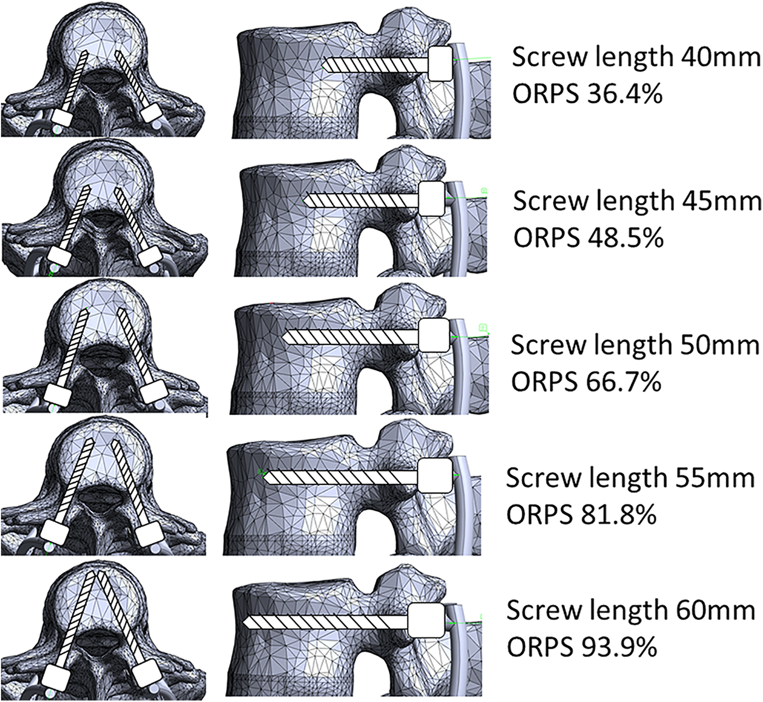
A nonlinear three-dimensional (3D) FE model of a lumbar spine (L1-S1) was designed using the FE software ADINA (ADINA R&D Inc, Watertown, MA, USA) from a computed tomography scan of a healthy 30-year-old male subject. This FE model is the same model previously used by Natarajan et al. 17 The articulating surfaces of the facet cartilage were approximated as frictionless 3D contact surfaces. The geometries of the vertebrae and the discs were meshed into a combination of eight-node brick elements and four-node tetrahedron elements. Based on the previous study, the material properties of each structure were modeled as follows; cancelous bone (Young’s modulus 100 MPa, Poisson’s ratio 0.2), cortical bone (Young’s modulus 12 GPa, Poisson’s ratio 0.3), facet cartilage (Young’s modulus 24 MPa, Poisson’s ratio 0.4), Posterior elements (Young’s modulus 3.5 GPa, Poisson’s ratio 0.25), endplate (Young’s modulus 24 MPa, Poisson’s ratio 0.4), and nucleus (Young’s modulus 0.8 MPa, Poisson’s ratio 0.49).18-22 (Table 1) Mooney—Rivlin hyperelastic material constants in annulus properties were 0.28 in C1 and 0.28 in C2. 18 The PS, which were set from L2 to S1, and the rod were modeled as titanium alloy (Ti-6AI-4 V, Young’s modulus 127 GPa, Poisson’s ratio 0.3). 17 The diameter of PS was set as 5.5 mm and the connected rod had a diameter of 6 mm and length of 160 mm. All PS were rigidly connected to the ROD.
The Each Material Properties.
C1 and C2 are heperelastic Mooney-Rivilin material constants of annulus.
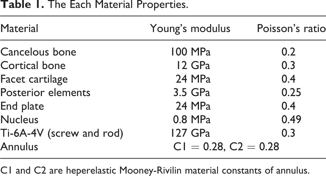
Compression force is a common method of loading vertebral body, but in this study, we focused on the flexion motion of the body trunk. 23 Therefore, the FE model was simulated as flexion motion to investigate loads at the UIV (L2) according to the length of PS. The reason for this is that Nachemson et al reported that flexion is the movement that places the highest load on the vertebral body. 24 Therefore, we focused only on the flexion motion in this study. There were 5 screw lengths examined: 40, 45, 50, 55, and 60 mm. The length of the PS is the length measured from the base of the rod. The S1 vertebral body was constrained in 3 principal directions. The moments of 8 Nm in flexion were applied by the application of 2 equal and opposite point loads on the upper surface of the L1 vertebral body (Figure 1). It was reported that the moments generated during daily activities ranged from 2 to 8 Nm. 25 The moment was applied downward at the foremost edge and upward at the posterior edge of the upper surface of L1. The maximum stress on the L2 vertebra (UIV) was shown as Von Mises stress.
FE model the moments of 8 Nm in flexion motion were applied downward at the anterior edge and upward at the posterior edge in the upper surface of L1.
ORPS in the UIV
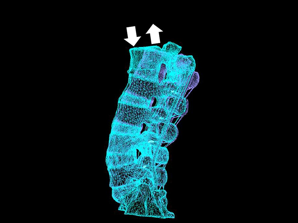
The ORPS was calculated as follows: ORPS = A/B×100, where A is the distance from the line of the posterior wall at UIV to the tip of the PS, and B is the anteroposterior diameter of the vertebral body (Figure 2).
How to calculate the Occupancy Rate of Pedicle Screw (ORPS) ORPS = A/B × 100. A indicated the distance from the line of the posterior wall in the vertebral body to the tip of the pedicle screw, and B indicated the anteroposterior diameter of the vertebral body.
FE Model Validation
The current FE model was validated in the previous published study that compared the range of motion (flexion/extension, torsion, and lateral bending) at each lumbar level in the FE model with that in a cadaver study. 26 Both the FE model and cadaver study results were within 1 standard deviation in flexion/extension and torsion and within 2 standard deviations at most levels in lateral bending.
Results
The ORPS Corresponding to the Length of Each Screw in UIV (L2 Vertebra)
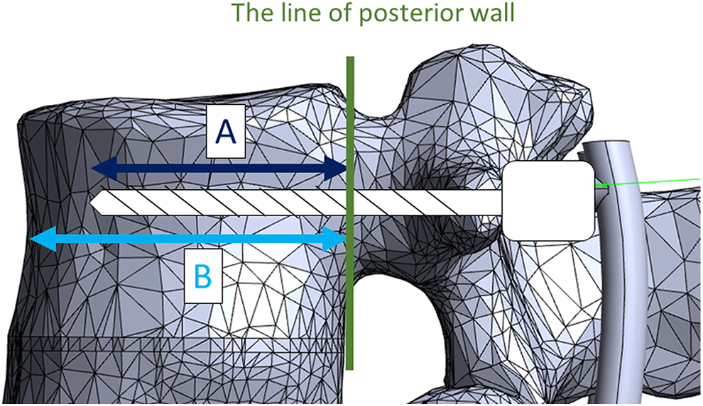
The ORPS corresponding to the length of each screw in UIV is shown in Figure 3. A (the distance from the posterior wall of the vertebral body to the tip of the PS) in the screw lengths of 40, 45, 50, 55, and 60 mm were 13.0, 17.3, 23.8, 29.2, and 33.5 mm, respectively. B (the anteroposterior diameter of the L2 vertebral body) was 35.7 mm. Therefore, screw lengths of 40, 45, 50, 55, and 60 mm were calculated as ORPS of 36.4%, 48.5%, 66.7%, 81.8%, and 93.8%, respectively.
The Occupancy Rate of Pedicle Screw (ORPS) for each screw length the screw lengths of 40, 45, 50, 55, and 60 mm were the ORPS of 36.4%, 48.5%, 66.7%, 81.8%, and 93.8%, respectively.
The Maximum Equivalent Stress on the Central Front Surface at UIV (L2 Vertebra)
The maximum equivalent stresses on the central front surface at the UIV according to each length of PS are shown in Figure 4. The maximum equivalent stress as the von Mises stress at the UIV according to lengths of 40, 45, 50, 55, and 60 mm were 0.838, 0.972, 0.869, 0.835, and 0.827 MPa, respectively.
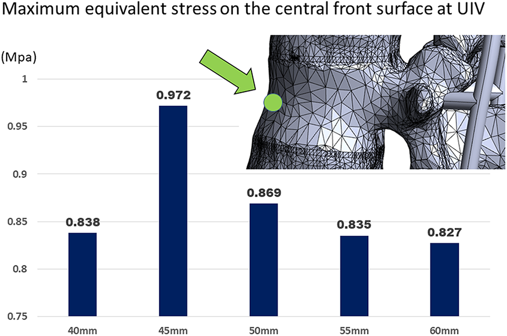
The maximum equivalent stress on the central front surface according to the screw length at upper instrumented vertebra (L2 vertebra).
The Maximum Equivalent Stress on the Screw Insertion Point at UIV (L2 Vertebra)
Similarly, the maximum equivalent stresses on the screw insertion point (only 1 side) at the UIV based on each screw length are shown in Figure 5. The maximum equivalent stresses at UIV according to the screw length of 40, 45, 50, 55, and 60 mm were 45.6, 37.2, 21.6, 13.3, and 14.8 MPa, respectively.
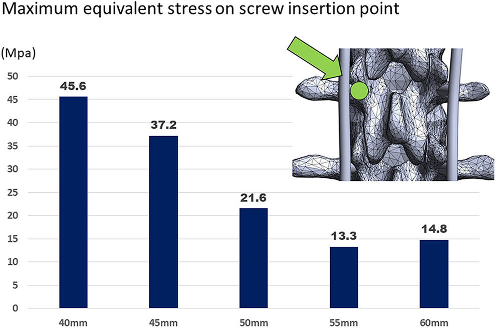
The maximum equivalent stress on the screw insertion point according to the screw length at upper instrumented vertebra (L2 vertebra).
Equivalent Stress Distribution at UIV (L2 Vertebra)
Figure 6 shows the equivalent stress distribution at the UIV (L2 vertebra). The markers indicated loads of 0.7 MPa or more. The load intensity increased in the order were blue (0.225-0.675 MPa), light blue (0.675-1.125 MPa), green (1.125-1.575 MPa), yellow-green (1.575-2.025 MPa), yellow (2.025-2.475 MPa), orange (2.475-2.925 MPa), red (2.925-3.375 MPa), and pink (3.375-MPa). The load is particularly high at the upper anterior edge of the vertebral body, the pedicle, and the screw insertion point. When focusing on the load on the vertebral body, we can see the light blue color up to 66.7% ORPS, but the light blue color disappears above 81.8% ORPS. In Figure 7, the markers are displayed only where stresses of 3.0 MPa or more are applied such that the area where strong stress is applied can be seen. Red markers were strongly observed in the vertebral bodies, pedicles, and screw insertion points. Markers were most strongly recognized at a screw length of 45 mm, then decreased at 40 mm and 50 mm, and no change was seen at 55 mm and 60 mm.
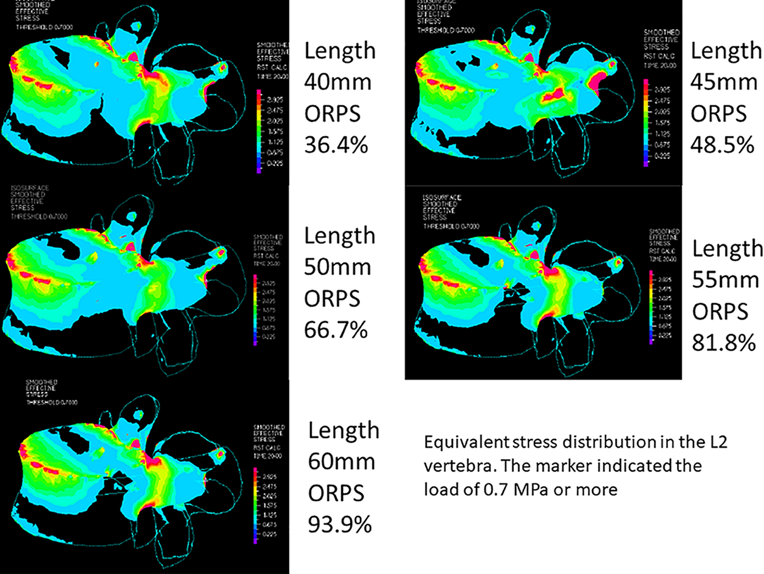
Equivalent stress distribution at the upper instrumented vertebra (L2 vertebra). The marker indicated the load intensity; blue (0.225-0.675 MPa), light blue (0.675-1.125 MPa), green (1.125-1.575 MPa), yellow-green (1.575-2.025 MPa), yellow (2.025-2.475 MPa), orange (2.475-2.925 MPa), red (2.925-3.375 MPa), and pink (3.375-MPa).
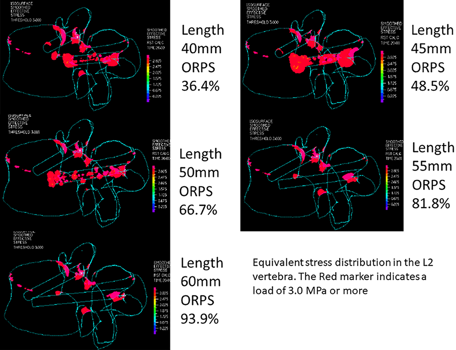
Equivalent stress distribution at the upper instrumented vertebra (L2 vertebra). The red marker indicated the load of 3.0 MPa or more.
Discussion
PJK is 1 of the most common complications of adult spinal deformity surgery; nevertheless, clinical symptoms are often asymptomatic or mild.1,2 By contrast, UIV fractures among PJFs can sometimes lead to the need for reoperation and severe symptoms.7,8 Oe et al reported that 58 (18.2%) of 318 patients who underwent ASD surgery suffered UIV fractures within 1 year. 9 The mean UIV level was T9 (±2) in both the UIV fracture and non-fracture groups with no significant difference (P = .654). Six of 58 patients (10.3%) developed severe paraplegia associated with spinal cord injury. Although less common, this complication, once it occurs, causes intense misery; therefore, it is very important to prevent UIV fractures. The study concluded that an ORPS of 73% or greater was important to prevent UIV fractures; all 6 patients with severe paraplegia had an ORPS of less than 73%. However, no biomechanical study has actually investigated the relationship between screw length and vertebral body loading. The present study is the first report to biomechanically demonstrate that a higher ORPS decreases the load on the vertebral body. Actually it has been reported that the pedicle accounted for 60% of the pull-out strength of the screw, and the remaining 40% was occupied by the cancelous bone in the vertebral body and anterior cortical bone.27,28 In other words, it is presumed that longer screws are important for stability. As shown in Figure 3, when the length of PS was 55 mm, ORPS exceeded 73% and increased to 81.8%.
Figure 4 shows that the maximum equivalent stress applied to the central front surface at the UIV was not large; however, it was maximal when the PS length was 45 mm, and the value was 0.972 MPa. Nevertheless, it should be noted that the maximum equivalent stress when the PS length was 40 mm (ORPS 36.4%) was 0.838 MPa, which was not as different from when the PS length was 55 mm or more. The reason was considered that short screw (ORPS 36.4%) caused less damage to the central front surface. However, with a shorter screw, the pull-out strength should be weak. Moreover, as shown in Figure 5, the maximum equivalent stress applied to the screw insertion point was much larger than the stress applied to the central front surface of the vertebral body. In particular, in the case of PS 40 mm, the maximum equivalent stress generated at the screw insertion point was 45.6 MPa, which was 54 times that of the stress applied to the central front area of the vertebral body. By contrast, the maximum equivalent stress applied to the screw insertion point decreased as the screw length increased; however, there was no significant change over the length of PS 55 mm or more (ORPS 81.8%). This result appears to be consistent with the results of our previous study where we showed that 73% or more of ORPS decreased UIV fractures. 9
Figure 6 shows the stress distribution above 0.7 MPa. Based on this figure, it is understood that the stress due to bending is likely to occur in the upper part of the vertebra, particularly in the upper front edge of the vertebral body, the pedicles, and the screw insertion point. Figure 7 shows that the stress distribution of 3.0 MPa or more was extracted in red color. This figure illustrates that it is impossible to reduce the stress applied to the upper anterior edge of the vertebral body, even with an increase in ORPS; however, it was possible to reduce the stress applied from the vertebral body to the pedicle and the screw insertion points. However, when focusing on the screw insertion point where the maximum equivalent stress is highest, it was 13.3 MPa and 14.8 MPa between 55 mm (ORPS 81.8%) and 60 mm (ORPS 93.9%) screw length, respectively, and the maximum equivalent stress could not be reduced by increasing the screw length.
It is difficult to prevent fractures of the anterior superior edge of the vertebral body even if the ORPS is high; however, it is possible to prevent fractures of the middle and posterior column. By contrast, if the ORPS is small, fractures of the middle and posterior column are a concern. In other words, it is thought that there is a high possibility of spinal cord injury due to unstable fractures and fractures near the spinal cord. These findings are supported by the previous study, in which all cases with paraplegia had an ORPS of less than 73%. 9 An FEA study by Wui et al indicated that bicortical screw fixation was also a risk of UIV fracture. Therefore, we should not use excessively longer screws to avoid bicortical screw fixation. 11
This study had 6 limitations. First, our FEA model did not consider the tension of soft tissue such as muscle or skin, although the range of motion was validated using cadaveric specimens by Renner et al. 26 Second, because this FEA model was a 30-year-old man, it is considered that the bone quality might be stronger than the case of patients undergoing ASD surgery. Moreover, whole spine alignment also should be quite different in young and elderly patients.
Therefore, it is not accurate whether the same results can be obtained with deformity surgery.
Third, because not only screw length but also diameter and trajectory may be related to equivalent stress distribution, it is necessary to compare equivalent stress distributions including screw diameter and trajectory in the future. Fourth, UIV fractures often occur in flexion motions while standing or sitting. Therefore, it is necessary to consider preload to approach more physiological conditions. In addition, in order to conduct motion analysis in general, it is necessary to consider not only flexion, but also extension, lateral bending, and rotation, which is also an issue for future study. 29 Fifth, the center of rotation of the L1 vertebral body was the center of rotation in the load condition; however, in actual flexion of the lumbar spine, the center of rotation should be located further posterior. The stress distribution on the vertebral body should also be different when physiological and non-physiological stresses are applied. Therefore, further studies are needed to make the loading conditions more physiological. Finally, the long fixation performed in ASD surgery involves fixation from the thoracic spine to the pelvis. Therefore, we cannot deny the possibility that the FE model in this study has a shorter fixation range and a different stress distribution.
In conclusion, in this study, strong loads are applied to the superior anterior edge of the vertebral body, the pedicles, and the screw insertion site in L2 vertebra by simulating the flexion motion instead of the general compression force. However, increasing OPRS to 81.8% or more could reduce the load on the vertebral body, pedicle, and screw insertion parts. To avoid spinal cord injury due to UIV fracture, intraoperative radiographs should be taken and longer screws should be placed if the PS length in the UIV is less than ORPS 81.8%.
Footnotes
Authors’ Note
This finite element analysis did not require approval by an institutional review board.
Acknowledgments
We are grateful that a part of this study was supported by the Strategic Core Technology Advancement Program (Supporting Industry Program) of The Small and Medium Enterprize Agency in Japan.
Declaration of Conflicting Interests
The author(s) declared no potential conflicts of interest with respect to the research, authorship, and/or publication of this article.
Funding
The author(s) disclosed receipt of the following financial support for the research, authorship, and/or publication of this article: Shin Oe and Yu Yamato belong to donated fund laboratory called Division of Geriatric Musculoskeletal Health. Source of funding is as follows: Medtronic Sofamor Danek Inc., Japan Medical Dynamic Marketing Inc., Meitoku Medical Institution Jyuzen Memorial Hospital. We have not received funding from the NIH, HHMI, or others.