
Abstract
The interference effect between the nano rotor and aerodynamic rudder was studied experimentally and computationally. Propulsive performance of nano rotor and aerodynamic performance of aerodynamic rudder were achieved experimentally. The disturbed flow field of nano rotor was also analyzed computationally to disclose the flow mechanics of the interaction. Results showed that the nano rotor has a great effect on the aerodynamic performance of aerodynamic rudder. The moment of aerodynamic rudder fluctuated with the rotor-to-rudder spacing and achieved the smallest value at the spacing of 0.5R. And the moment of aerodynamic rudder varied with deflection angle linearly. Aerodynamic rudder influenced the propulsion performance of the nano rotor slightly. The thrust coefficient and torque coefficient increased a little with spacing but changed slightly with the deflection angle. Numerical simulation showed that aerodynamic rudder blocked the flow field of the nano rotor and the counterclockwise rotation of the rotor drives the flow in the downstream rotating in a counterclockwise direction resulting in the different angle of attack between left and right rudder surface.
Introduction
Aerodynamic rudder is one of the useful methods to control the attitude of rotary-wing nano air vehicle (NAV) 1 due to the limitation of its size and weight2–6 The interaction between nano rotor and aerodynamic rudder induces complex flow phenomenon and influences the performance of both nano rotor and rudder. Therefore, it is necessary to study the interference effect and disclose the inherent flow mechanics so as to design nano rotor and rudder with high performance7,8
Nano rotor is characterized by small size and low rotational velocity causing that its operational Reynolds number is very low which is usually below 2.0 × 10⁴ or less. At low Reynolds number, it is laminar flow and unstable9–11 Due to the weak inertia force in the boundary layer, strong adverse pressure gradient appears at the maximum suction point of the leading edge. As a result, the flow separates from blade surface and wake vortices generate. The vortices interact with rudder resulting in the change of control efficiency of rudder. On the contrary, the rudder in the wake flow blocks the wake flow of the nano rotor and influences the propulsion performance of the nano rotor.
The interference effect between propeller and wing is well studied. Fratello et al. 12 investigated the mutual interference of large propeller and wing using wind tunnel and lifting surface method. Results showed that the drag coefficient of the wing increased while the lift coefficient of the wing decreased. On the other hand, both the thrust coefficient and power coefficient of the propeller increased. Moens and Gardarein 13 used the actuator disk model to replace the propeller. And the interference effect between the slipstream of propeller and wing was studied using Navier–Stokes (N–S) solver. Gamble and Reeder 14 tested the interaction between a micro propeller and a wing in the wind tunnel and it was found that 12% to 18% thrust of the propeller transformed to the drag of the wing. Hu et al. 15 studied the influence of the rudder to the wake flow of propeller. Potential flow method was used to establish the integrated formulation of the strength of doublet at the surface of propeller blade. As the induced flow velocity was solved, the influence of the rudder to the propeller was detected. Wang and Xiong 16 employed Reynolds average N–S equations to establish the interference model of propeller to rudder. Results showed that the propulsion performance of the front propeller was not sensitive to the horizontal and vertical position of the rudder. Yang 17 proposed a method for studying the rudder performance in the wake flow of propeller using the lifting surface method. The calculated results were in good agreement with the experimental values. Duan and Ma 18 analyzed the influence of propeller slipstream to the aerodynamic performance of the wing at different angles of attack using the sliding mesh technique. And results showed that the thrust of propeller changed as the result of wing and the lift of wing increased at high angle of attack because of the influence of propeller.
In summary, the experimental and numerical methods are mainly employed to study the mutual interference effect between the rotor or propeller and the wing. These researches provide the study of interference of nano rotor and aerodynamic rudder with some references for experimental and numerical methods. However, the interference effect between rotor and rudder is scarcely studied because most of research focuses on the aerodynamic interaction between propeller and wing. As the aerodynamic rudder operates at different deflection angles, it has a high impact on the propulsion performance of rotor, especially at the high deflection angle. Therefore, it is necessary to investigate the mutual interference between rotor and rudder. Furthermore, most of the aforementioned researches studied the interaction at high Reynolds number. It shall be pointed out that the rotary-wing NAV operates at an ultra-low Reynolds number. At ultra-low Reynolds number, the phenomenon, that is laminar separation and laminar separation bubble, appears due to the adverse pressure gradient in the boundary layer, which results in the unsteady non-linear aerodynamic characteristics for flight vehicles. 19 In this paper, the mutual interference effects between nano rotor and aerodynamic rudder at ultra-low Reynolds were therefore studied experimentally and numerically. The influence of rudder deflection angle and rotor-to-rudder spacing to nano rotor propulsion performance and aerodynamic rudder aerodynamic performance was investigated. And the interfered flow field of nano rotor was studied to find out the radical reason for the variation of rotor performance. It is believed that the research will provide the design of rotary-wing NAV with a reference.
Experimental setup
Nano rotor and aerodynamic rudder
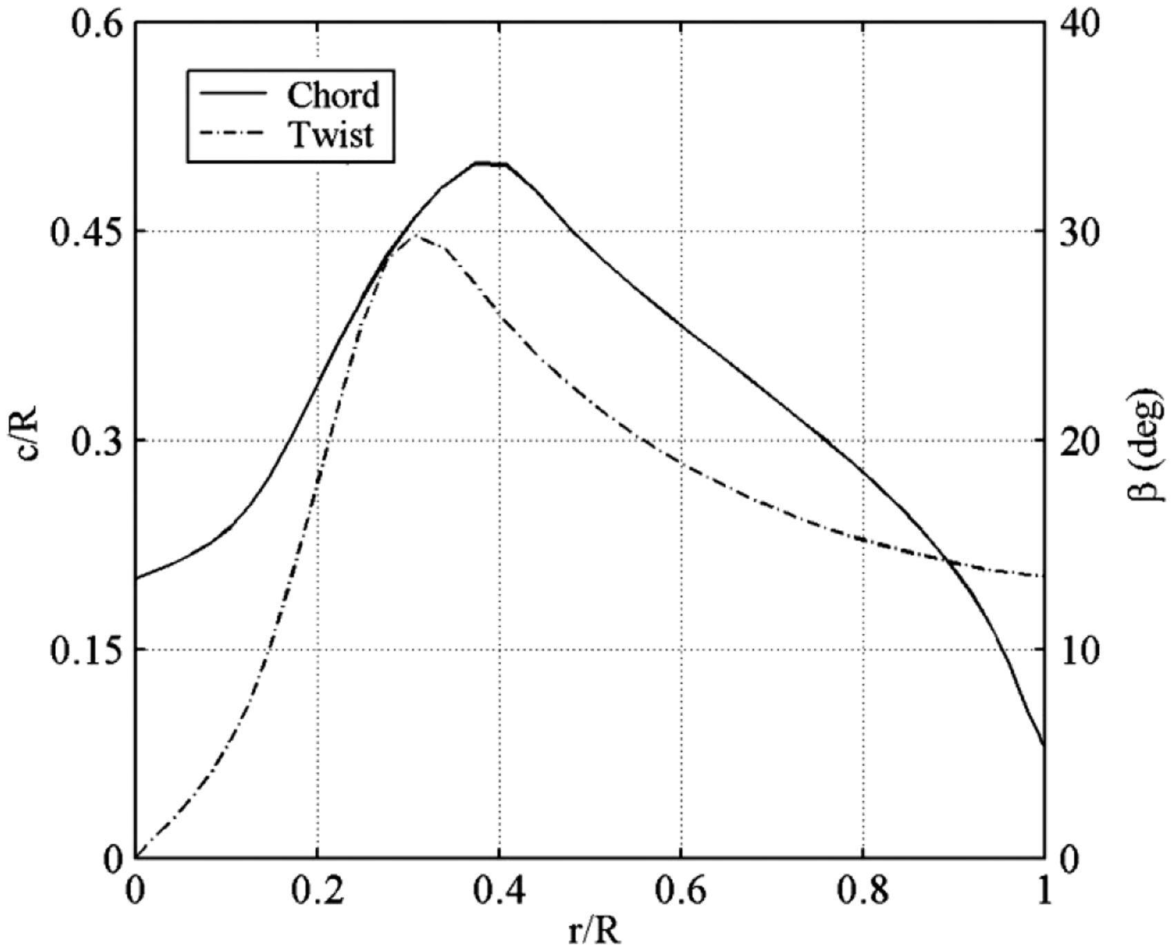
Conventional helicopter rotor typically has uniform chord. It controls attitude and fight direction through collective and cyclic pitch control. Because small micro air vehicles are characterized by extremely small size and weight, conventional controls are not feasible. Therefore, rotor blades with twisted and non-uniform chord are particularly attractive for propulsion optimization. Thus, a nano rotor with diameters of 7.5 cm was designed based on low Reynolds number aerodynamics and minimum induced loss theory to minimize energy loss. The blade airfoil has 2% thickness with 5% curvature circular arc. The rotor has a mean chord of 0.33R and mean twist angle of 17.21 as shown in Figure 1. The geometry of nano rotor is shown in Figure 2. The solid line represents the chord of the rotor varying with radius, corresponding to the left axis. The dotted line represents the blade twist varying with radius, corresponding to the right axis. After obtaining chord length and twist angle distribution, the nano rotor was fabricated with carbon laminar and epoxy resin.

Blades chord and twist distribution of nano rotor.
Schematic of nano rotor.
To control the attitude of rotary-wing NAV, an aerodynamic rudder system is installed in the wake flow of nano rotor. The aerodynamic rudder system includes two pieces of rudder as shown in Figure 3. Each piece of rudder is a rectangle flat plate whose the long edge is 0.8R long and the short edge is 0.53R long. Here R represents the radius of nano rotor. To avoid the influence of motor and increase the control efficiency of aerodynamic rudder, a horizontal spacing of 0.4R exists between two pieces of rudder. The rudder was fabricated with carbon laminar and epoxy resin as well with a thickness of 0.3 mm.

Schematic of aerodynamic rudder.
Interference effect test bench
An interference effect test bench was designed to measure the thrust and torque of nano rotor and the control moment and force of rudder due to interference effect as shown in Figure 4. To describe the moment of the rotor and the rudder conveniently, two coordinate systems are introduced. One coordinate system locates at the center of the rotor, i.e. O-XYZ, and the other coordinate system locates at the center of the balance, i.e.

Schematic of interference effect test bench.
The rudder system consists of the aerodynamic rudder, a small servo, a control panel, a six-degree of freedom (6-DOF) balance, and a support beam. The aerodynamic rudder was assembled horizontally with a support beam under the wake flow of nano rotor. The support beam was fixed on the small servo by which the rudder can change its deflection angle accurately. The control command was generated by the computer. Then it was transferred to the servo by virtual of control panel typed Arduino Mega, ATmega1280. The 6-DOF balance is an ATI nano 17 (Ti) balance with a maximum force capacity of 14.1 N and a maximum moment capacity of 50 N mm. The accuracy is 1.0% for the force and it is 1.25% for the moment. The aerodynamic force and moment can then be measured with the balance.
The nano rotor test part consists of the nano rotor, speed controller, a torque sensor, a load cell, and a support beam. In order to establish the pure torque of the rotor, an ultra-low-capacity static torque sensor DH15 by the SCAIME company with a capacity of 0.005 N m and an accuracy class of 0.1% was used to measure the torque. In addition, the load cell with an accuracy of 0.2% for measuring the thrust was a load cell Honeywell Model 31 with a capacity of 2.0 N. The torque cell was installed on the load cell directly. And an extended supporting beam was installed vertically supporting the motor and rotor to avoid the effect of the torque. The controller was YGE4-BL for brushless motors. The speed control command generated by computer was transferred to speed controller with which the rotational speed of nano rotor can be adjusted.
The energy supply system is a regulated DC power supply, which can adjust the voltage and stabilize it at a certain value to provide micro motor and servo with current.
The data acquisition system was composed of a speedometer, an amperemeter, a voltmeter, a MDR data recording system, and an USB analog-to-digital data acquisition of NI USB-6251 BNC. The speedometer was used to measure the speed of nano rotor. The electric parameters measurement system consists of an amperemeter and a voltmeter to measure the input current and voltage. The MDR acquisition system and the USB-6251 can acquire the torque and force parameters of nano rotor and aerodynamic rudder. A control software was developed to generate control command and save the acquisition data.
Computation methodology
To capture the detailed flow field characteristics of nano rotor, computational fluid dynamics (CFD) method was used20–24 Because of the special flight condition of nano rotor, the operating Reynolds number of nano rotors is typically lower than 20,000 with regard to the chord length at the blade station of 3/4R and the blade tip Mach number of nano rotors is less than 0.1 Ma. For low-Mach and low-Re flow, conventional N–S equations might fail to converge to a correct solution. Since the rotor rotates at high speed, the rotor motion can be regarded as a quasi-steady state during numerical simulation when the rotation is stable. Therefore, 3D incompressible N–S (INS) solver was used to compute the aerodynamic performance of nano rotor at ultra-low Re. The simulation was performed based on N–S equations in a coordinate system which rotates around the y-axis with an angular velocity Ω. The steady incompressible N–S equations in integral form for an arbitrary control volume are written in three dimensions as follows
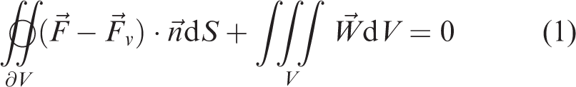
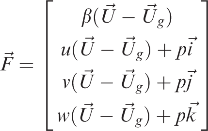


Here,


The equations were solved with finite volume method and Roes flux scheme was employed.
The numerical simulation was performed using FLUENT V6.3, a software package capable of solving Euler equations, RANS equations, or space-filtered equations. The conservation of mass, momentum, energy, and so forth, can be obtained using finite volume method. Several spatial discretization schemes are provided by Fluent such as first-order upwind, second-order upwind, power law, QUICK, and third-order MUSCL. In this study, the first-order upwind scheme and QUICK scheme were applied. Since the rotation of rotor can be taken as a quasi-steady case, multi reference frame (MRF) was applied to describe the rotor rotation 25 The MRF model is a steady-state approximation in which individual cell zones use different frame equations to solve N–S equations. Zones containing moving components can then be solved using moving reference frame equations, whereas stationary zones can be solved with stationary frame equations. At the interfaces between cell zones, a local reference frame transformation is performed to enable flow variables in one zone to be used to calculate fluxes at the boundary of the adjacent one. It is convenient to use MRF so that the steady-state solutions are possible with relatively short computing time and relatively high precision. Thus, as shown in Figure 5, the flow field is divided into three zones in which two small zones are dedicated to the nano rotor and the aerodynamic rudder, respectively. The external mesh boundary is formed by a 25.33R high cylinder with the top and bottom radii of 12R and 16R, respectively. Every small block has a height of 2/3R and a diameter of 1.5R. The upper small block is dedicated to the nano rotor which rotates around the y-axis with an angular velocity Ω as shown in Figure 6. And the lower small block is a static fluid zone for aerodynamic rudder. The fine O-topology was employed and the distance of between the first layer of mesh and the solid surface is 5.0 × 10⁻⁴ m. The number of grid cells for the upper block is 1.8 million and that for lower block is 1.9 million. The total number of grid cells for the whole flow field is about 6.0 million. The grid independent study was carried out and the results indicated that the same simulation results were obtained when the grid number reached 6 million, suggesting that the mesh used in the study was reliable.

Global view of the mesh.

Surface mesh of nano rotor and aerodynamics rudder.
Experimental and computational design
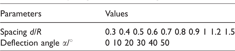
To investigate the interference effect, two parameters that are rotor-to-rudder spacing d and rudder deflection α shall be studied, as shown in Figure 7. Experiments were carried out with spacing varying from 0.3R to 1.5R while rudder deflection angle changes from 0° to 50° with an increment of 10°. The detailed parameters were listed in Table 1. Therefore, 60 groups of experiments were performed with different rotor-to-rudder spacing and rudder deflection. During the experiments, the nano rotor was driven by motor MICRO at a voltage of 3.6 V. At this voltage, the rotational velocity could be adjusted by the controller with Pulse width modulation (PWM) signals. But all the experiments were performed with the rotor rotational velocity of 6500 r/min. Aerodynamic rudder was driven by a small servo to adjust rudder deflection angle. The moment of aerodynamic rudder was measured with the 6-DOF balance. And the thrust and the torque of nano rotor were measured with load cell and torque sensor, respectively.
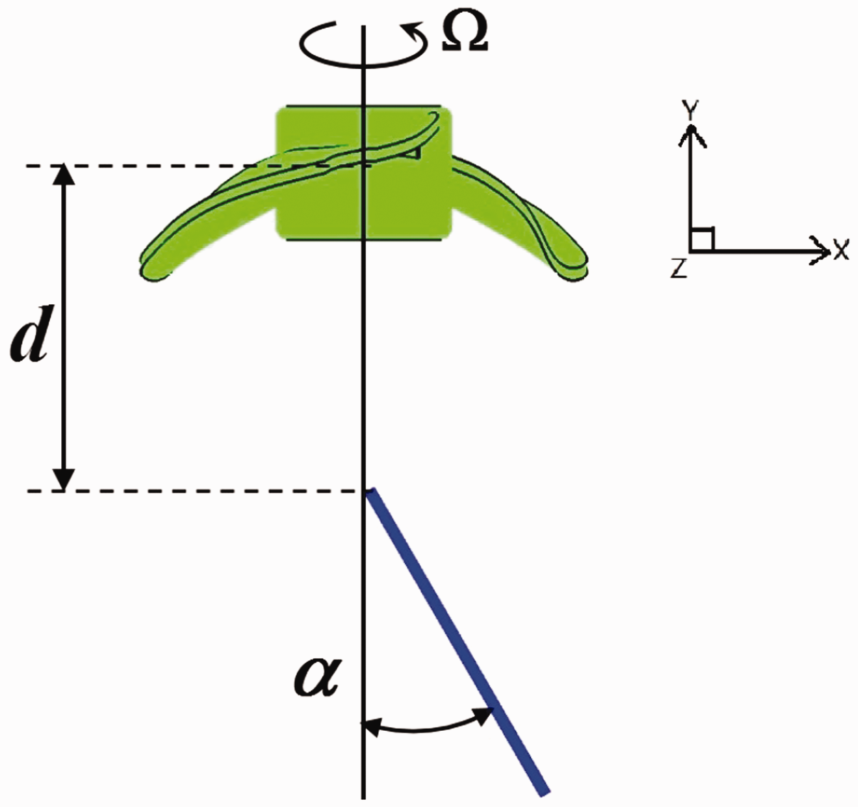
Definition of spacing and rudder deflection angle.
List of spacing and deflection angle.
The experimental data collected by the MDR acquisition system belong to temporal signal which often superimposed by various signals, such as high-frequency signals and low-frequency signals. In addition, the signals generated by the rotor are mainly low-frequency signals due to the low weight of nano rotor. The traditional Fourier transform is difficult to get the desired results. Therefore, all the signals were processed with EMD (Empirical Mode Decomposition) analysis tools during the experiment to eliminate the influence of external disturbance. EMD is an adaptive data processing or mining method, which can be theoretically applied to the decomposition of any type of time series. Therefore, it is suitable for the processing of non-linear and non-stationary time series. Prior to the experiments, calibrations of test benches were performed to eliminate non-linearity of load cell and uncertainty factors. The calibration was carried out before the experiments. Results showed that the relative fit errors of load cell are very small and that of the torque sensor is higher.
In the experiment, two principal sources of uncertainty are contained. One is the bias errors inherent in the measurement devices with regard to offset and drift, and the other is the precision error. The precision error of measurement was calculated using the Kline–McClintock method for error propagation. If there are multiple independent measurements, one possibility is in terms of the standard deviation, or perhaps the range as defined by the maximum value minus the minimum value. The Kline–McClintock method can determine the uncertainty of a calculation given certain measurements and the tolerances on those measurements. All of the results have a confidence of 95% in experiments.
The computation was performed to observe the detailed flow field of nano rotors to find inherent reason of the variation of rotor performance and rudder performance induced by the mutual interference between the nano rotor and the aerodynamic rudder. Simulations were carried out at the rotational velocity of 6500 r/min for the nano rotor. And the rotor-to-rudder spacing is 0.5R while the deflection angle of aerodynamic rudder is 30°. The flow field of nano rotor without aerodynamic rudder was also simulated as a reference. A short cylinder with diameter of 10 mm was added at the center of rotor to take into account the influence of motor. The computations were performed on HP station with 40 CPU and 64 GB memory for one week.
Results and discussion
Aerodynamic performance of aerodynamic rudder under interference
Prior to the simulation, the grid independent study was carried out for a case in which the distance between the propeller and rudder is 0.53R and the rudder deflection angle is 30°. The grid number is from 2 million to 10 million. As shown in the Figure 8, results indicated that the thrust coefficient and torque coefficient changed little with the grid number once it is higher than 6 million. Therefore, the following computations are carried out with the mesh of 6 million grid cells. Figure 9 shows the variation of the moment with spacing between rotor and rudder. Generally, the moment of aerodynamic rudder fluctuates with the spacing for all deflection angles. Besides, the amplitude of fluctuation increases with the deflection angle of aerodynamic rudder. And the moment reaches 0.37 N mm at high deflection angle. The least moment is achieved at a rotor spacing of 0.5R whereas the highest moment is achieved at a rotor spacing of 1.5R. When the spacing is lower than 0.5R, it is found that the moment drops with the increase of spacing. In addition, the moment augments with the increase of spacing from 0.5R to 1.0R except for 0.7R. However, it varies little with spacing when the spacing is larger than R. Since the slipstream of nano rotor influences the generation of moment, the distribution of induced velocity of nano rotor determined the moment.
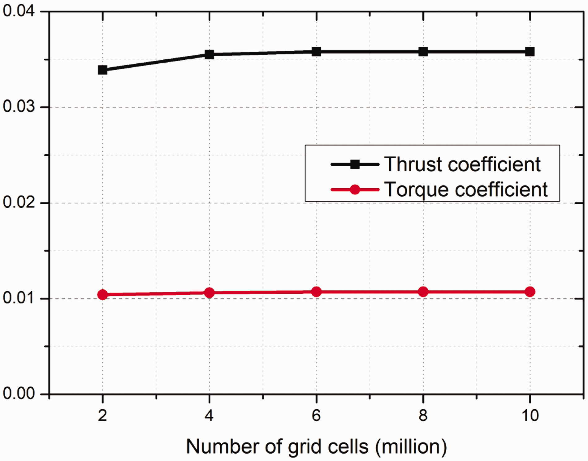
Thrust coefficient and torque coefficient varying with the number of grid cells.

Rudder moment varying with spacing.
Figure 10 shows the variation of rudder moment with defection angle. It is found that the moment of aerodynamic rudder increases with deflection angle nearly linearly. However, the slope of the curve varies with the spacing. The lowest slope was found at the spacing of 0.5R and the highest slope was found at the spacing of 1.5R. It shall be pointed that the slope does not change a lot with the spacing.

Rudder moment varying with deflection angle.
Propulsion performance of nano rotor under interference
To analyze the propulsion performance of nano rotor under interference clearly, the experimental results obtained at fixing rudder deflection angle or at fixing spacing was presented. Figure 11 shows the thrust coefficient of nano rotor varying with spacing and rudder deflection angle. It is found that the thrust coefficient fluctuates with the spacing. In general, the thrust coefficient decreases slightly with spacing. It is illustrated that the aerodynamic rudder will influence the rotor thrust coefficient a little. The thrust coefficient of nano rotor increases slightly with the increase of deflection angle. Since the higher deflection angle enhances the interference effect, the thrust of nano rotor increase as a result. Figure 12 shows the torque coefficient of nano rotor varying with spacing and rudder deflection angle. Results show that the torque coefficient drops slightly with spacing, which states that the interference effect becomes weak as the rudder leaves away from the nano rotor. And the torque coefficient of nano rotor varies little with the deflection angle. Compared to the study by Wang and Xiong, the same conclusion can be drawn that the thrust coefficient and torque coefficient increases slightly with spacing. The aerodynamic rudder influences the propulsive performance of nano rotor slightly.

Thrust coefficient of nano rotor varying with spacing and deflection angle.
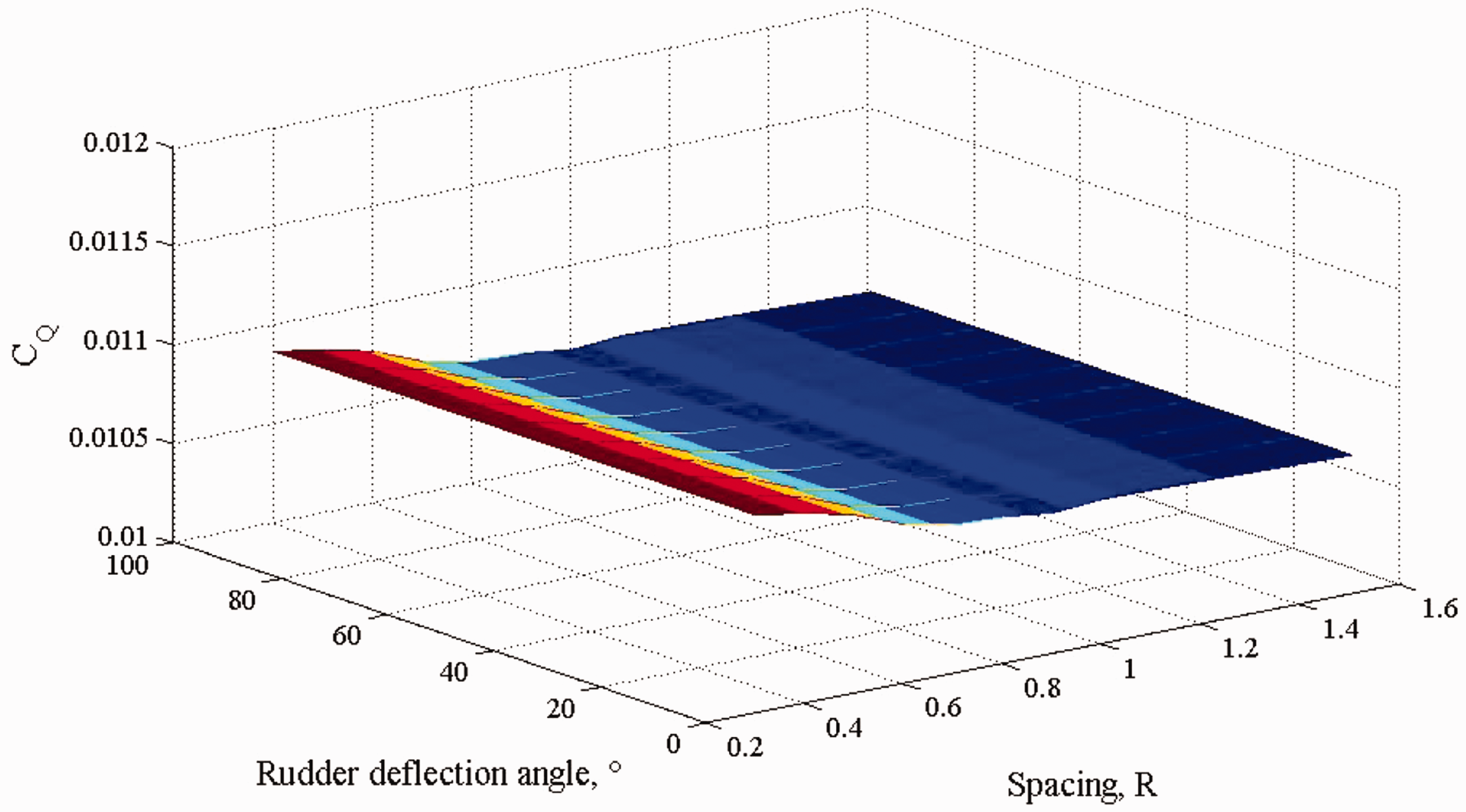
Torque coefficient of nano rotor varying with spacing and deflection angle.
Flow field analysis
The flow field analysis data were obtained from numerical simulation. Figures 13 and 14 show the pressure coefficient contour on the press surface and suction surface of rotor with and without rudder. The distance between the propeller and rudder is 0.5R and the rudder deflection angle is 30°. Results show that the distribution of pressure coefficient (

Contour of pressure coefficient of press surface: (a) single rotor and (b) rotor with rudder.

Contour of pressure coefficient of suction surface: (a) single rotor and (b) rotor with rudder.

Dimensionless velocity magnitude contour: (a) single rotor and (b) rotor with rudder.

Pressure coefficient contour of aerodynamic rudder.

Streamtraces over rotor: (a) left rudder and (b) right rudder.
Comparison of experimental and numerical results
Figure 18 show the comparison of experimental and computational rudder moment at different spacing and rudder deflection angle. It can be concluded that the experimental and computational results of rudder moment agree well at different rudder deflection angle. However, at different spacing, the CFD results show that the rudder moment firstly increases with spacing and then become independent with spacing. The experimental results show that the rudder moment firstly decrease with spacing. When the spacing is larger than 0.53R, the rudder moment increases with spacing. The possible reason for this discrepancy is that experiment was disturbed by the stick connecting the two rudders.

Comparison of experimental and computational rudder moment at (a) different spacing with 30° deflection angle and (b) different rudder deflection angle with 0.53R spacing. CFD: computational fluid dynamics.
Conclusion
In this paper, the interference effect between the nano rotor and aerodynamic rudder was studied experimentally and computationally. An experimental platform was established. And propulsive performance of nano rotor and aerodynamic performance of aerodynamic rudder were achieved experimentally at different rudder-to-rotor spacing and deflection angle of rudder. Compared with previous investigations, new attitude control method of the interference effect between rotor and rudder was considered and studied. Compared with the studies at high Reynolds number, the study considered the laminar separation and laminar separation bubble at ultra-low Reynolds number and non-linear aerodynamic characteristics for flight vehicles. The disturbed flow field of nano rotor was also analyzed computationally to disclose the flow mechanics of the interaction. It is found that the nano rotor has a great effect on the aerodynamic performance of aerodynamic rudder. The moment of aerodynamic rudder fluctuates with the rotor-to-rudder spacing. And the moment drops with the increase of spacing when the spacing is lower than 0.5R but it augments with the spacing from 0.5R to 1.0R. Analysis reveals that the distribution of induced velocity results in the fluctuation. And the moment of aerodynamic rudder varies with deflection angle linearly. The influence of spacing and rudder deflection angle to the propulsion performance of nano rotor was also studied. It is found that the thrust coefficient and torque coefficient increase slightly with spacing but change little with the deflection angle. Numerical simulation of interference between rotor and aerodynamic rudder showed that aerodynamic rudder blocks the flow field of the nano rotor and the counterclockwise rotation of the rotor drives the flow in the downstream rotating in a counterclockwise direction resulting in the different angle of attack between left and right rudder surface. In summary, the aerodynamic performance of aerodynamic rudder is influenced greatly by the nano rotor. The moment of aerodynamic rudder varies with spacing and deflection angle. The propulsion performance of nano rotor is influenced slightly by the aerodynamic rudder. In the further work, the different rotational speeds of nano rotor shall be studied. And the visual experiment using Particle Image Velocimetry (PIV) will be carried out.
Footnotes
Declaration of conflicting interests
The author(s) declared no potential conflicts of interest with respect to the research, authorship, and/or publication of this article.
Funding
The author(s) disclosed receipt of the following financial support for the research, authorship and/or publication of this article: The authors would like to thank the support of National Natural Science Foundation of China (Grant No. 11302164), Specialized Research Fund for the Doctoral Program of Higher Education of China (20130201120031), and the Fundamental Research Funds for the Central Universities (Grant No. xjj2013031).