
Abstract
In this paper, the bionic membrane structure is introduced to improve the aerodynamic performance of nano rotor at the low Reynolds number. The aerodynamic characteristics of nano rotor made of hyperelastic material as membrane blades are studied. Firstly, based on the hyperelastic constitutive model, a finite element model of the rotor is established and compared with the results of the modal test to verify the accuracy of the model. Then the computational fluid dynamics model of membrane nano rotor is established which combined with the finite element model. The aerodynamic characteristics of the membrane rotor under hovering conditions are studied using fluid–structure interaction method. It is found that the calculation results matched well with the experiment results. The design of the structural parameters such as the membrane proportion, shape, and position of the membrane rotor is optimized. The influence of each parameter on the aerodynamic performance of the rotor is obtained. Under certain structural conditions, the performance can be effectively improved, which provides a new idea for the design of the nano rotor.
Keywords
Introduction
The nano vehicle is small in size, light in weight, and easy to carry. It has a variety of flying capabilities such as low-speed flight, vertical take-off and landing, and hovering. Therefore, it has important military and civilian values,1–4 such as unmanned reconnaissance, information transmission, and target tracking tasks in complex and narrow spaces, as well as environmental monitoring, disaster investigation, search, etc. However, the nano rotor is flying at a low Reynolds number, the influence of the viscous force increases significantly, and it is easy to cause laminar flow separation and reduce the aerodynamic performance of the rotor. Liu et al. 5 study the aerodynamic performance of the U-80 micro propeller in a hovering state. It is proved that the figure of merit for the micro propeller is much lower than regular helicopters. To improve the propulsion performance of the rotor, the traditional optimization design method mainly changes the rotor geometry profile and aerodynamic configuration.6–9 However, the improvement of nano rotor is limited due to its small size.
From the perspective of the bionic structure, the surface of membrane can be deformed according to the different incoming flow environments, thereby changing the aerodynamic layout to achieve the improvement of aerodynamic performance. Studies have found that the improvement comes from the interaction of the leading-edge vortex and the turbulent boundary layer. The asymmetric flow structure generated by the movement of the membrane rotor increases its lift. 10 Combining existing theories and previous experiments,11–15 this paper uses dielectric elastomer (DE) materials to make membrane blades. In the study of membrane wings, Cheney et al. 16 of Brown University found that the wings of bats are different from birds or insects. It consists of an extremely thin skin covering the forelimbs and straddling the tail of the finger, including organized elastomer and skeletal muscle. This membrane structure can control the shape of the wings during flight and improve its aerodynamic performance. The research of Jillian RB 17 from Brown University also found that membrane wings have a variety of aerodynamic advantages at low Reynolds numbers. It can passively adapt to flow conditions and effectively delay stall compared to rigid wings. On the other hand, the membrane wing can achieve a high angle of attack flight through active flow control and improve aerodynamic performance. Barbu et al. 18 of Southampton University studied the effects of DE membrane prestress, thickness, loading voltage, and flexible electrode size on material performance and aerodynamic characteristics, and established an experimental model and test platform for a flat and straight wing. Under working conditions, the flexible membrane improves the aerodynamic performance of the straight wing.
However, the above studies mainly stay in the mechanism analysis or are only applied to the research of flat wings. Based on previous research and the feasibility of the bionic membrane rotor, the investigation of the bionic membrane rotor is carried out in this paper. Firstly, the membrane rotor is designed, tested, and simulated. The accuracy of structural model is verified by the modal test. Then the computational fluid dynamics (CFD) model is established and fluid–structure interaction investigation is carried out to design and study the rotor parameters. Finally, conclusions are summarized that the structural parameters of the membrane rotor have a great influence on the aerodynamic characteristics of the nano rotor.
Calculation method
Computational fluid dynamic methods
The law of fluid flow can be described by the conservation of energy, mass, and momentum, and the Navier-Stokes (N-S) equation is used to numerically solve the rotor flow field environment. Its operating state is at a low Reynolds number, and the viscous force has a greater influence, so the viscous effect is considered. The three-dimensional incompressible and viscous N-S equation of the nano rotor is synthesized as follows 19 :
Continuous equation:
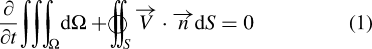
Momentum equation:
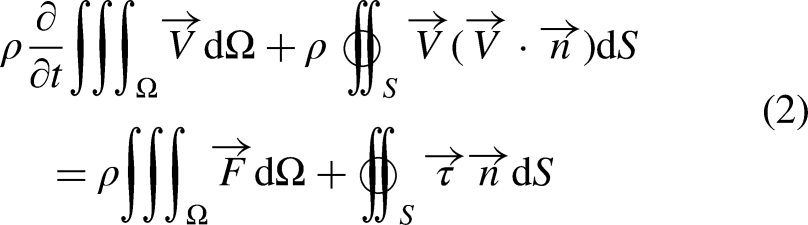
Energy equation:

Complex turbulence simulation consumes a lot of computing resources and cannot be completely accurate. However, its transient control equations in time and space may be uniform. Modifying the control equations from this perspective will greatly reduce the amount of calculation and ensure the accuracy of the model to a certain extent. The amount of calculation for Reynolds Average Navier-Stokes (RANS) is small and its accuracy can meet the needs of research. Therefore, the turbulence calculation adopts the RANS method, and the two-equation standard
In the CFD analysis, the rotation of the rotor is considered. Therefore, the dynamic domain model is needed to solve the problem and the multiple reference frame (MRF) method is used. Each sub-domain maintains an independent motion posture and converts the speed to an absolute speed on its interface to realize the exchange of flow field information, which can greatly reduce the consumption of computing resources and maintain high calculation accuracy.
Fluid–structure interaction methods
Taking into account the flexible characteristics of the membrane rotor itself, there is a deviation compared with the actual situation when it is used as a rigid structure to study its aerodynamic performance. During the working process, the membrane rotor will be deformed under the influence of aerodynamic force, which will react to the flow field around the rotor, thus forming a typical fluid–structure interaction problem. Therefore, a fluid–structure interaction method is needed to study and analyze the aerodynamic characteristics of the rotor under actual operating conditions. The fluid-structure interaction of the nano rotor takes place between the flow field and the blade, with the airfoil as the interface, where the aerodynamic force and the structural displacement are in a coordinated relationship. The fluid-structure interaction is solved by establishing the relationship equation on the coupling surface. Taking into account the complexity of the nano rotor flow field, this paper uses a separation coupling method to study the fluid-structure interaction of the rotor.20,21 The fluid–structure interaction simulation calculation for the hovering conditions of the rotor involves the coupling of flow field analysis and structural analysis and the interpolation exchange between data. The flow diagram is shown in Figure 1.
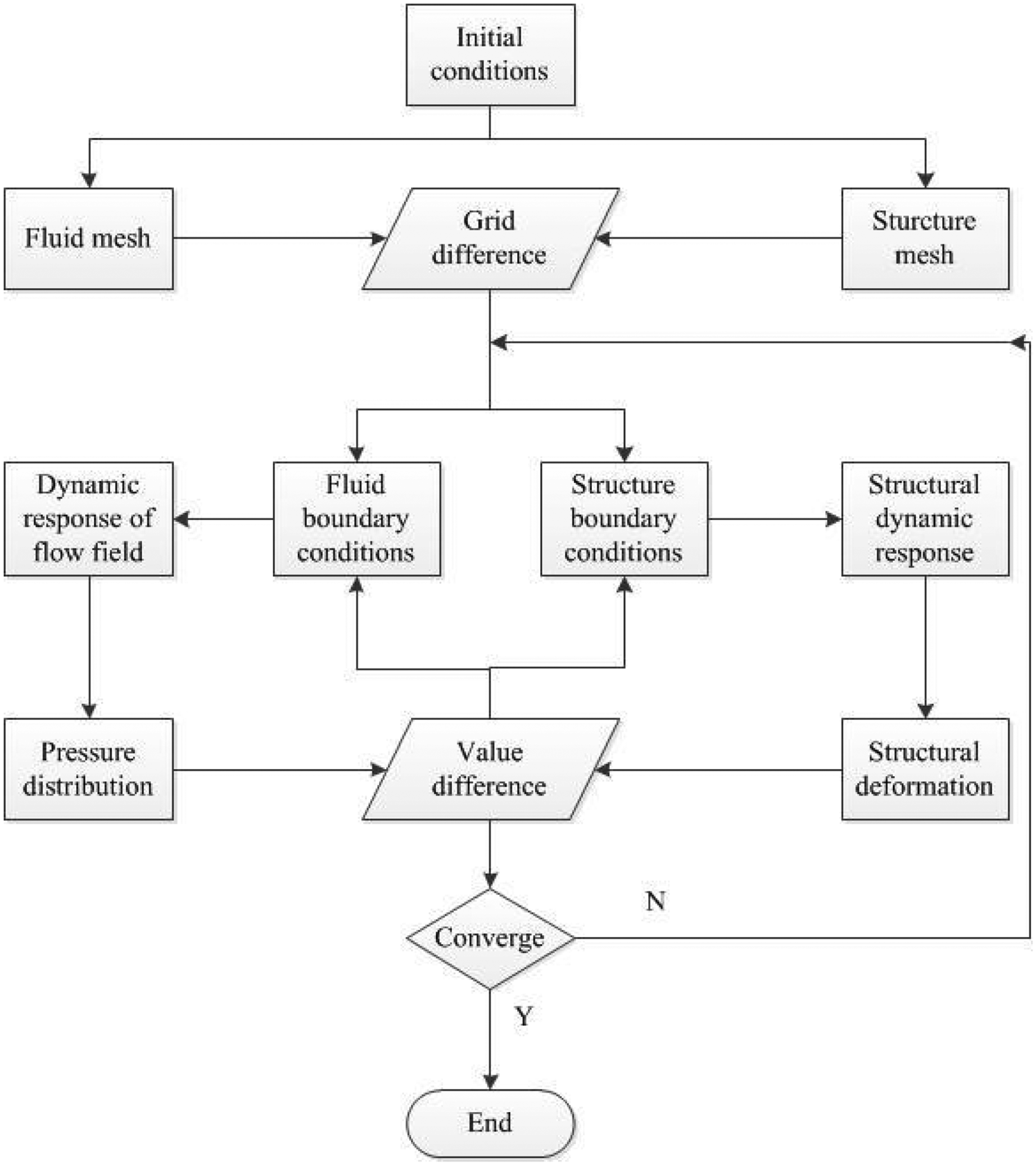
Flow diagram of fluid–structure interaction.
Regarding the solution of the structural domain, the structural equation is:


Fluid–structure interaction calculation
Calculation model and conditions
According to the hyperelastic constitutive model of DE material, 23 the structural model of the membrane rotor is established. The supporting part of the membrane rotor and the whole normal rotor materials are carbon fiber composite materials. Considering that the actual thickness of the rotor is difficult to describe quantitatively, the geometric model of the rotor is treated as equal thickness. In the model, the axis of rotation of the rotor is defined as the Z-axis, and then the plane of the paddle is the XY-plane. Figure 2 shows the design of the membrane rotor and its structural model. The radius of the rotor is 37.5 mm and the thickness is 0.4 mm. The two planes in the middle of the rotor are fixed support conditions, and the number of structural grids is 38,000.

Membrane rotor and structure model.
The structural response of the model is analyzed. Table 1 shows the natural frequency comparison of the two rotor models. It can be found that the frequency of the membrane rotor is significantly reduced, which is greatly affected by the flexibility of the DE material. In order to verify the accuracy of the structural model, a structural response test is carried out on the designed membrane rotor. From the comparison of natural frequencies, it can be seen that there is not much difference between the simulation and experimental results, and the natural frequency of the experimental results is relatively low. The maximum error occurs is 3.36% at the fourth-order frequency and only the first four modes are observed in the experiment. The result should be caused by the flexibility of the material, and it is difficult for the speaker to excite high-order frequencies. In general, the structural model established here is considered relatively accurate.
Comparison of rotor natural frequency.

The calculation parameters of the structural model are set, and the middle position of the rotor is fixed to simulate the fixed effect of the rotor root. The aerodynamic force input by the aerodynamic model is applied to the corresponding position of the rotor as a surface force, and the resulting structural response displacement is transmitted to the aerodynamic model as an output. The time step of structural calculation is consistent with that of aerodynamic calculation.
In the aerodynamic model, the MRF method is used to establish the rotor rotation flow field model to realize relative movement. 24 The outer flow field of the model is generally truncated cone or cylindrical. 25 During the actual rotation of the rotor, there are complex flow characteristics such as tip vortices and wake vortices in its downstream area. The downstream part of the calculation domain should be larger than the upstream part in both axial and radial dimensions, so the truncated cone-shaped outer flow domain is used in the aerodynamic model. According to the MRF method, the entire calculation domain is divided into two sub-domains, as shown in Figure 3, which are the static domain and the rotation domain respectively. The data transfer between the two domains is done through the interface. The radius of the rotor is R = 37.5 mm, and the model dimensions are as shown in the figure. The reference length L is the chord length at the blade station of 3/4R, so Re = UL/ν = 19563.54, which is in the lower Reynolds number range. According to the geometry of the rotor and the outer flow field, multiple areas combined with an O-shaped structure and unstructured grids are used for meshing in the research. The rotation domain is divided by an unstructured grid. Considering the laminar flow and dense pressure gradient around the rotor surface, the height of the first grid near the rotor surface is set to 0.01 mm. The outer flow field grid uses a double O-shaped topology to improve the quality of the outer flow field grid, which can better realize the development of wakes. Prior to the simulation, the grid-independent study is carried out for the normal rotor in the hover state. The grid number is from 2 to 10 million. As shown in Table 2, results indicated that the thrust coefficient and torque coefficient changed little with the grid number once it is higher than 6 million. Therefore, the following computations are carried out with the mesh of 8 million grid cells. The total number of grids is 8 million, which can meet the convergence and accuracy requirements.
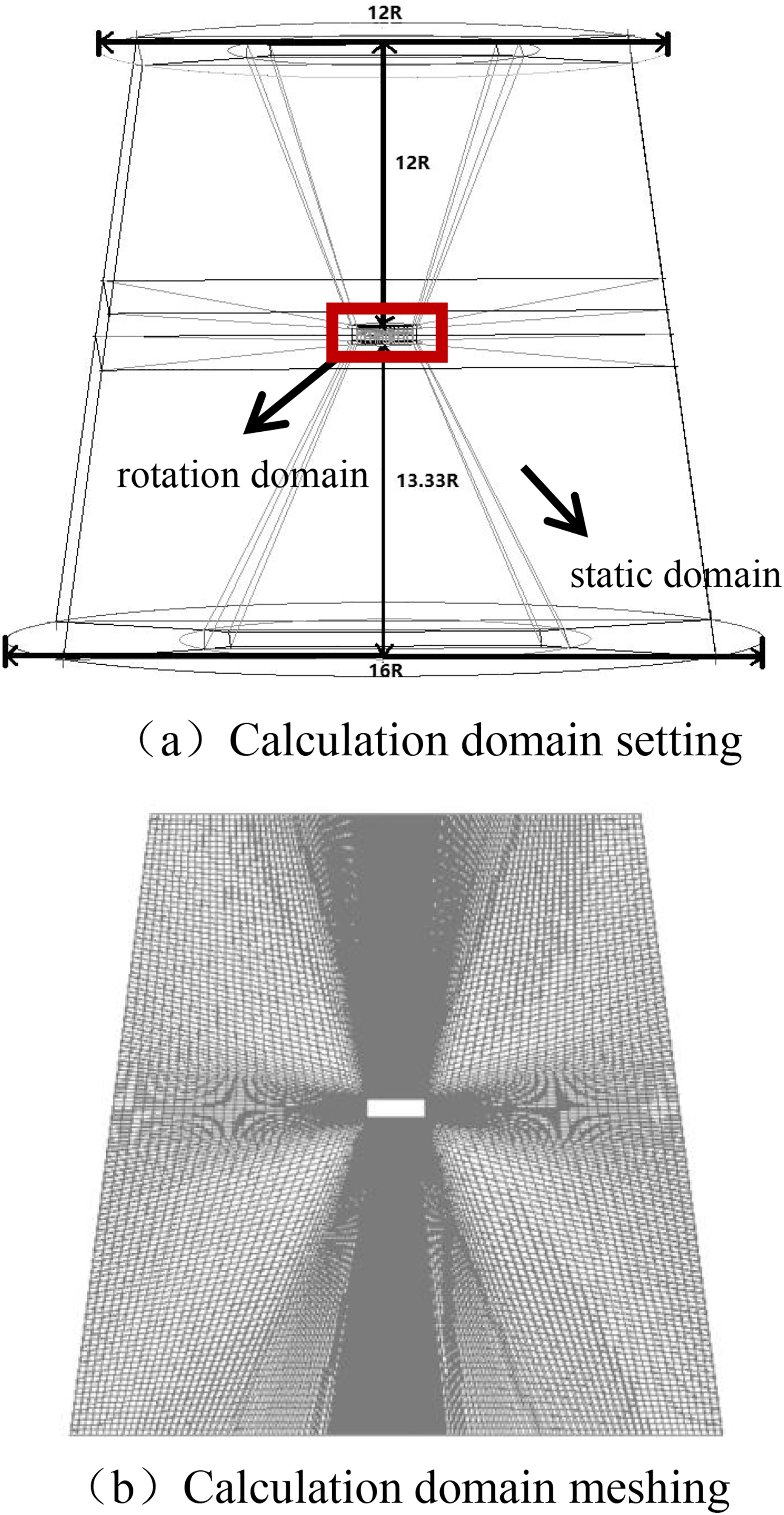
Overall aerodynamic model: (a) calculation domain setting and (b) calculation domain meshing.
The grid independent study results.

Based on the accurate aerodynamic and structural models of the membrane rotor, the fluid–structure interaction study of the membrane rotor is carried out. The validation of the FSI solver is verified in literature. 26 First, the steady-state solution of 6500 r/min under no angle of attack is performed, and then the transient solution is started, and the coupling surface is set as the rotor surface. In order to ensure the accuracy and convergence of the simulation results, the time step is set to a minimum for better convergence, and each time step is iterated up to 30 times.
Calculation results and analysis
The fluid–structure interaction calculation of the membrane rotor and the normal rotor is performed until convergence, and the structure and aerodynamic results are compared and analyzed. Figure 4 is the displacement contour of the normal rotor and the membrane rotor at the final time step. The deformation of the rotor under the action of fluid-structure interaction is all shown as up shots. The maximum displacement of the normal rotor is 0.36959 mm, and the deformation of the membrane rotor is significantly larger than it, the maximum is 2.7067 mm. The addition of DE material greatly reduces the rigidity of the rotor, and will produce greater deformation when subjected to the same force.
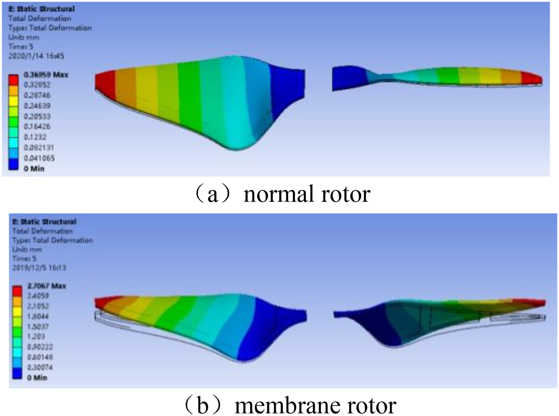
Rotor displacement contour: (a) normal rotor and (b) membrane rotor.
Figure 5 shows the strain contour of the rotor at the final time step. In a normal rotor, the root is a high-stress area, and its width is small. The flexibility of the rotor is mostly derived from this, so the strain is prone to occur here, and the maximum strain is 0.0033 mm. The change of the structure of the membrane rotor makes the strain of the membrane position larger when the rotor surface is subjected to the same aerodynamic force, and the maximum strain is 0.015 mm. Under the same aerodynamic conditions, the structural deformation is more severe, which has an impact on aerodynamics.

Rotor strain contour: (a) normal rotor and (b) membrane rotor.
In terms of aerodynamic contour, the flow field of the membrane rotor under the final time step is analyzed and compared with the normal rotor. Figure 6 is a comparison of the pressure contour of the lower surface of the rotor. It can be seen from the figure that the pressure on the lower surface of a normal rotor gradually increases from the root to the tip. Therefore, it corresponds to the phenomenon of maximum displacement at the wingtip of the structural response. While the membrane rotor has this law, it also reflects the influence of the DE membrane on its aerodynamic force. The leading edge of the rotor shows a large pressure.

Pressure contour of the low surface: (a) normal rotor and (b) membrane rotor.
Further, the pressure changes on its upper and lower surfaces and the law of surface flow at the chordwise section are observed. Figure 7 shows the pressure coefficient contour of the rotor at different cross-sectional positions from the root to the tip. The left side is the leading edge. It can be seen that the pressure coefficient contour at the root of the rotor is obviously different, and the flow field changes significantly due to the influence of the membrane material. Normal rotors have a small angle of attack at the root position, and a reverse pressure difference appears at the leading edge, that is, the pressure coefficient of the upper surface is significantly higher than that of the lower surface, which cannot provide effective lift at this position. The high-pressure zone of the root position of the membrane rotor appears on the lower surface and shifts backward from the leading edge position. The reason is that the deformation of the membrane material increases the camber of the airfoil, which increases the velocity of the upper airfoil and increases the airfoil pressure difference. Since the aerodynamic lift of the rotor at the root position is small, if this phenomenon occurs at the middle position of the wing, the aerodynamic performance of the membrane rotor may be improved. The contrast of the pressure coefficient contour at other positions is more similar, and the airfoil pressure difference of the normal rotor will be larger, which can provide greater aerodynamic force. Moreover, it can be observed that the leading-edge vortex of a normal rotor is easier to form a complete attachment than the membrane rotor, which leads to better performance of normal rotor. Further analysis of the reason why the pressure difference cannot be increased in other positions of the membrane rotor is that the radius of rotation in other positions is larger, and the linear velocity and the aerodynamic force received are greater. In the case of greater aerodynamic force, the membrane material deforms greatly beyond the usable range, so that the aerodynamic performance cannot be effectively improved. It is predicted that it will be improved when the membrane position is appropriately changed or the overall material flexibility is reduced.

Pressure coefficient contour of rotor section (left: normal rotor; right: membrane rotor): (a) 0.1 R, (b) 0.1 R, (c) 0.5 R, (d) 0.5 R, (e) 0.9 R and (f) 0.9 R.
Figure 8 shows the comparison of the spanwise vorticity at 0.5 R of the rotor. The left side of the figure is the leading-edge position, and the right side is the trailing edge position. It can be observed that there are complicated vortex structures at the trailing edge, but the vortex volume of the membrane rotor has been reduced. The shedding of the leading edge vortex has not been improved, and the aerodynamic performance has been reduced. Further research is needed to improve the performance of the membrane rotor.
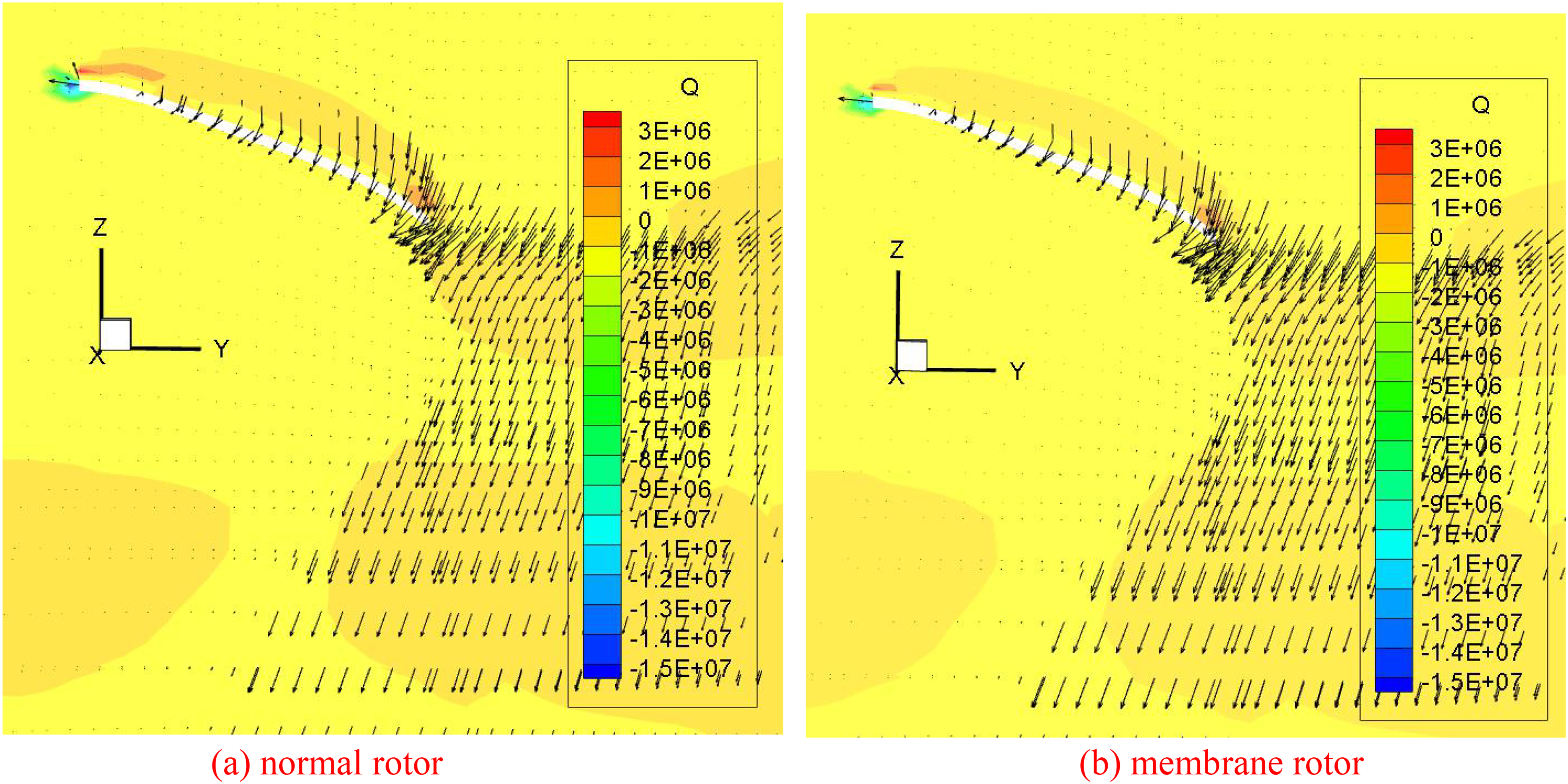
Spanwise vorticity distribution at 0.5 R: (a) normal rotor and (b) membrane rotor.
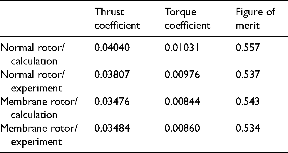
At the same time, the hovering performance test is carried out on the designed rotor. The performance parameters are shown in Table 3. Compared with the experimental results, the simulation calculation has slightly higher values, and the maximum error of the figure of merit is 3.7%. This is because the simulation environment is more ideal, but the rotor has many unquantifiable influences such as the accuracy of the measuring device and the complexity of environmental variables in actual work. In general, the simulation method is considered to be accurate. The thrust and torque of the membrane rotor are relatively small compared to the normal rotor. From the comparison of its figure of merit, it is believed that the membrane rotor under this design parameter cannot achieve an effective improvement in aerodynamic performance, but the improvement of the aerodynamic performance at the root position of the wing provides an idea for further optimization design. Further research on each parameter will be carried out to improve the performance of the nano rotor.
Comparison of rotor propulsion performance.
Structural parameter analysis
Based on the fluid–structure interaction analysis results above, and considering the proportion, shape, and position of the membrane, six membrane rotors with different structures are designed. Only one side of the rotor is shown in Figure 9, the yellow part is a membrane. Rotor (Figure 9(a)) is the membrane rotor used above. The membrane is placed on the leading edge. At this time, it is affected by the windward side and the deformation is large. Therefore, the membrane is placed on the trailing edge in the subsequent structures. Among them, Figure 9(b) and (c) have the same membrane shape, but in Figure 9(c), the rear edge is closed. The ellipse shape is adopted in Figure 9(d), and the proportion of membrane increases in Figure 9(f) compared with Figure 9(b). The fluid–structure interaction analysis of the membrane rotors with the following structures is carried out.

Membrane rotors of different structures: (a) square membrane on the leading edge, (b) square membrane on the trailing edge, (c) square membrane in the middle, (d) oval membrane on the trailing edge (e) Oval membrane in the middle, (f) larger square membrane on the trailing edge and (g) larger square membrane in the middle.
First, the structural response is analyzed, and the displacement, stress, and strain data are shown in Table 4. It can be seen from the data that when the membrane is located at the leading edge, it is affected by the oncoming flow. At this time, the displacement, stress, and strain of the rotor are the largest, and the structural response is the most severe after being subjected to the same aerodynamic force. Comparing Figure 9(b) and (c), the structure response will be reduced when the trailing edge is closed. Comparing Figure 9(b) and (f), when the membrane shape is the same, the structure response will increase correspondingly when the proportion is increased. Comparing Figure 9(d), (e) and (f), (g), changing the shape will have a certain effect on the structural response, but when the trailing edge is closed, its effect is smaller and the structural response is similar.
Comparison of rotor structural response.

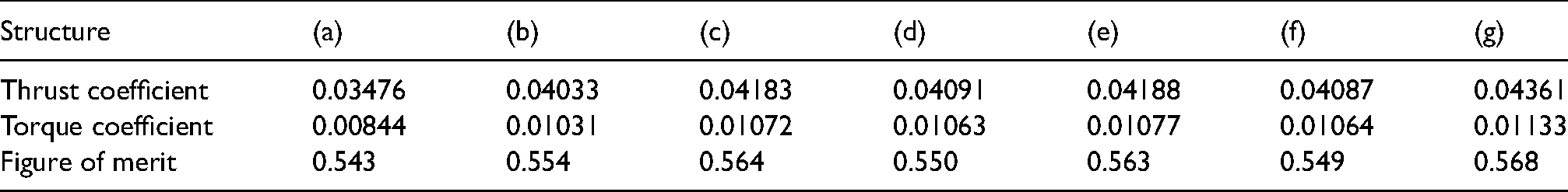
As for the aerodynamic performance, its thrust coefficient, torque coefficient, and figure of merit are shown in Table 5. It can be seen from the data that when the membrane position is at the trailing edge, the aerodynamic performance is significantly improved. Under the same membrane shape, when the rear edge is closed, the performance is also improved. Comparing the calculation results of the fluid-structure interaction of normal rotors, the performance of the membrane rotors under the two structures Figure 9(e) and (g) has been significantly improved, while the increase in Figure 9(g) is greater. The proportion of membrane of the two structures is basically the same, so it is considered that the performance of Figure 9(g) is better when considering the relatively uniform linear velocity. The aerodynamic performance of Figure 9(c) is slightly different from that of normal rotors. At this time, the membrane occupies a relatively small proportion and the front and rear edges are closed. It has no significant effect on the performance of the rotor. Comparing the membrane rotors under the two structures of Figure 9(f) and (g), under the same membrane shape, the closed trailing edge will significantly improve its aerodynamic performance. To sum up, the aerodynamic performance of Figure 9(g) is better, which has a larger proportion of membrane and closed front and rear edges. Therefore, further compare the flow field contour of membrane rotors of Figure 9(a), (c), (f) and (g), and analyze the influence of different positions, different shapes, and closed front and rear edges on the aerodynamic performance of the membrane rotor.
Comparison of rotor aerodynamic performance.
It can be seen from the airfoil pressure contour shown in Figure 10 that the membrane rotor is affected by the position of the membrane, and its pressure distribution is obviously different. When the membrane is positioned at the front edge, its high-pressure zone is inclined to the front edge, and when the membrane is positioned at the rear edge, its high-pressure zone is inclined to the rear edge. Secondly, comparing Figure 10(c) and (g), it can be seen that under this structure, when the proportion of the membrane increases, the aerodynamic pressure of the lower surface increases significantly, which improves the aerodynamic performance. In contrast Figure 10(f) and (g), under the same membrane shape, the trailing edge of Figure 10(f) is not closed. At this time, the deformation of the membrane is obviously increased and has an adverse effect on the performance, and the pressure on the lower surface is significantly reduced.

Pressure contour of the membrane rotor low surface: (a) square membrane on the leading edge, (b) square membrane in the middle, (c) larger square membrane on the trailing edge and (d) larger square membrane in the middle.
It can be seen from the cross-sectional pressure coefficient contour shown in Figure 11 that the large pressure difference of Figure 11(a), (c) and (f) is mainly concentrated in the leading edge, which is similar to a traditional rotor. The leading edge is where the airflow develops more intensely. Different structures of membrane rotors can effectively change the flow field distribution on the rotor surface. Among them, the leading edge of Figure 11(f) has a small pressure difference, but a certain pressure difference also appears at the trailing edge under the influence of the membrane of the trailing edge. Figure 11(g) is affected by the membrane, the pressure coefficient of the lower surface increases significantly, and a large pressure difference distribution also appears at the trailing edge. It can provide greater lift, and the aerodynamic performance has been significantly improved.
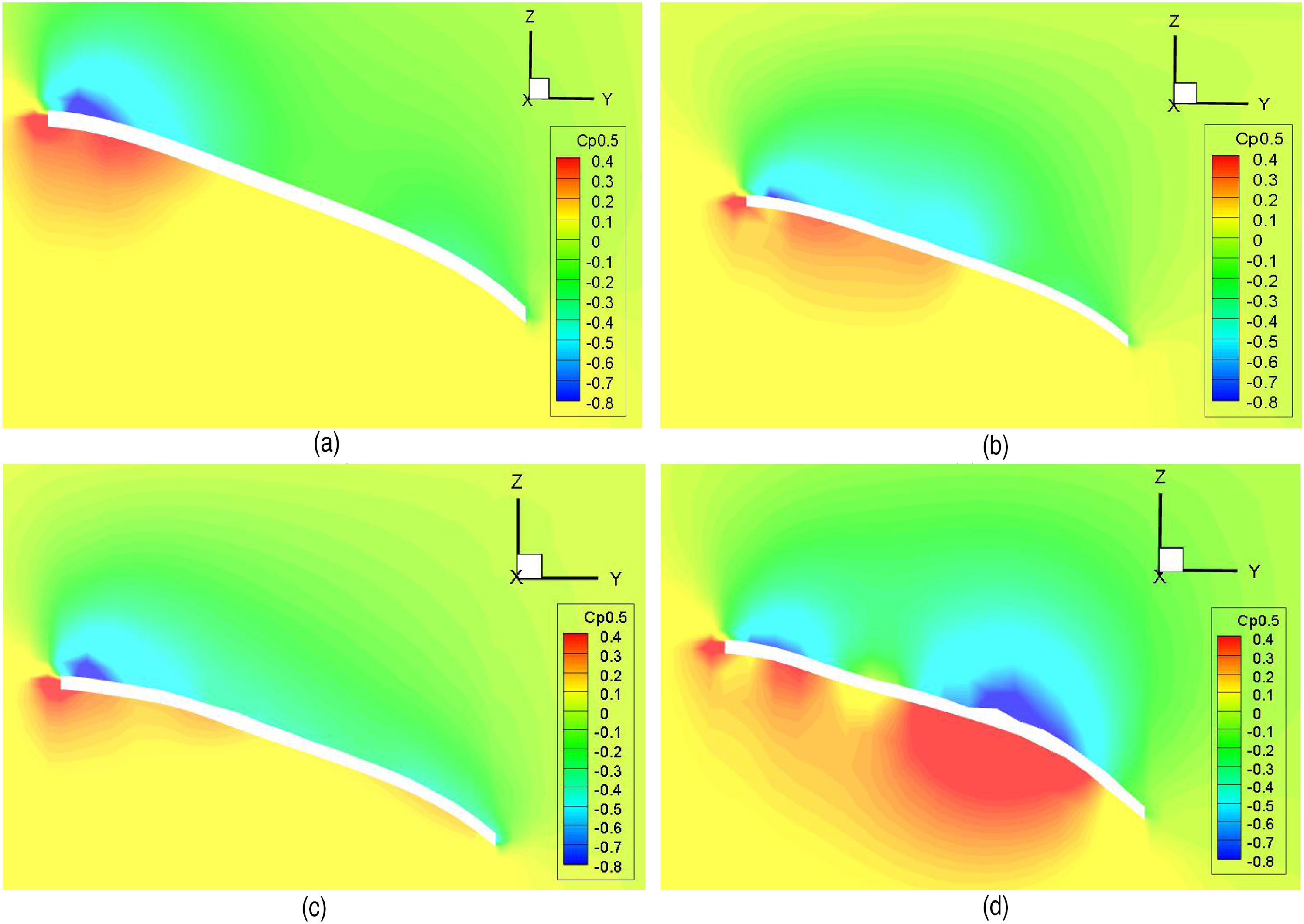
Pressure coefficient contour of blade section at 0.5 R: (a) square membrane on the leading edge, (b) square membrane in the middle, (c) larger square membrane on the trailing edge and (d) larger square membrane in the middle.
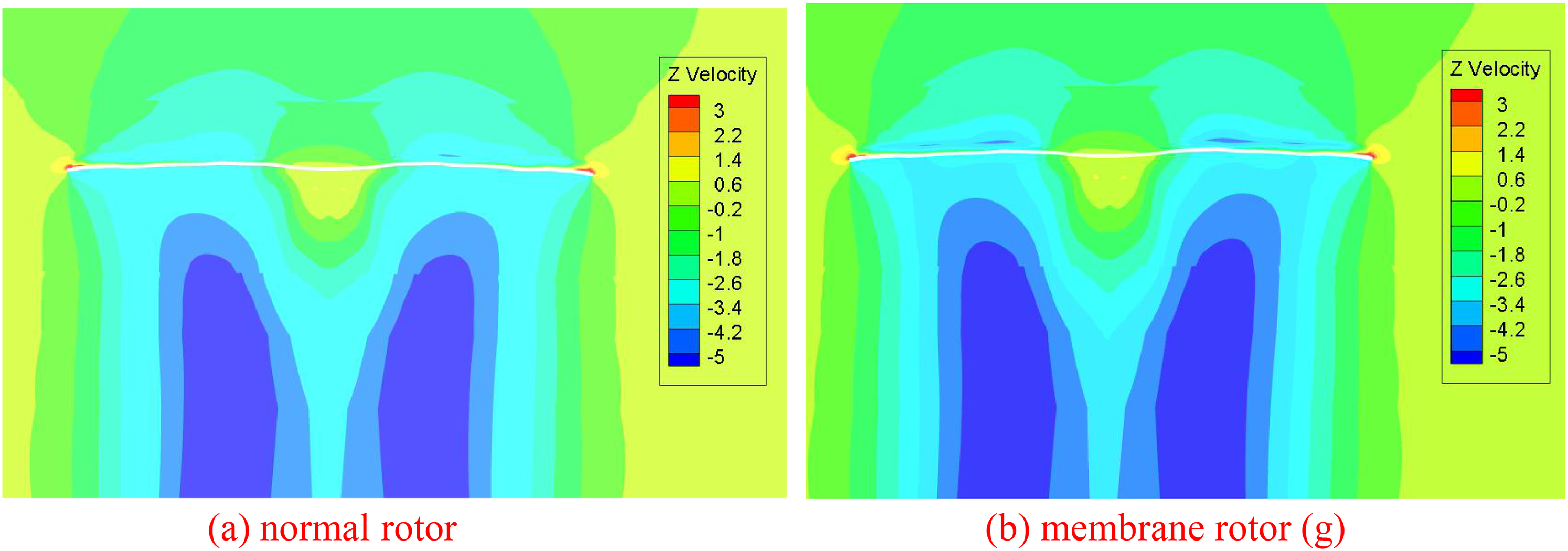
Wake velocity contour: (a) normal rotor and (b) membrane rotor (g).
In terms of flow velocity, the comparison of the rotor velocity and flow field is shown in the figure below. It can be clearly seen that the flow velocity above and below the plane of the paddle plate is significantly accelerated due to the influence of the membrane structure, and the airflow is subjected to stronger suction and higher flow velocity. This will produce a greater pressure difference, thereby improving the aerodynamic performance of the rotor.
Conclusion
In this paper, the aerodynamic characteristics of the membrane nano rotor are studied experimentally and computationally. The experimental platform is established for the modal test and hovering performance test based on the verification of experiment, the accurate structural model and aerodynamic model are established to carry out the fluid–structure interaction study of membrane rotor. From structural response and aerodynamic contour, the structural parameters of the membrane rotor are optimized and analyzed, and the influence of each parameter on the aerodynamic characteristics of the rotor is obtained. In summary, the aerodynamic performance of Figure 11(g) is better, and its main structure is a membrane rotor with closed front and rear edges, and the membrane occupies a relatively large proportion and the shape is more regular. At this time, the membrane rotor has a certain deformability, which can effectively improve the surface flow characteristics, thereby improving the aerodynamic performance of the nano rotor. In further work, large eddy simulation and detachment vortex simulation shall be studied to get more accurate calculation results.
Footnotes
Acknowledgements
The authors are grateful for the support from the National Natural Science Foundation of China through grant nos. 11772252 and 11302164. The authors also acknowledge the support of the K.C. Wong Education Foundation.
Declaration of conflicting interests
The authors declared no potential conflicts of interest with respect to the research, authorship, and/or publication of this article.
Funding
The authors disclosed receipt of the following financial support for the research, authorship, and/or publication of this article: This work was supported by the National Natural Science Foundation of China (grant nos. 11302164, 11772252).